Image Steganography Using LSB Algorithm
Pravin B. Desai1, Pradip S. Bhendwade2
Assistant Professor, Dept. of E&Tc, Ashokrao Mane Engineering College, Kolhaour, Maharashtra, India1 Assistant Professor, Dept. of E&Tc, Ashokrao Mane Engineering College, Kolhaour, Maharashtra, India2
ABSTRACT: Since communication is most important factors of information technology and communication has been the security of information. Cryptography was created as a technique for securing the secrecy of communication and many different methods have been developed to encrypt and decrypt data in order to keep the message secret. This paper describe at transmission and receiving side that includes ARM7 controller that must encode the secret text into the cover image as well as decode the text from stego image, and zigbee module to transmit that image to destination throughout the destination as well as to receive the stego image.
KEYWORDS: Cryptography, Steganography, zigbee.
I. INTRODUCTION
Since the rise of the Internet one of the most important factors of information technology and communication has been the security of information. Cryptography was created as a technique for securing the secrecy of communication and many different methods have been developed to encrypt and decrypt data in order to keep the message secret. Unfortunately it is sometimes not enough to keep the contents of a message secret, it may also be necessary to keep the existence of the message secret. The technique used to implement this, is called Steganography.
It is the art and science of invisible communication. This is accomplished through hiding information in other information, thus hiding the existence of the communicated information. Today Steganography is mostly used on computers with digital data being the carriers and networks being the high speed delivery channels. Steganography differs from cryptography in the sense that where cryptography focuses on keep in the contents of a message secret, Steganography focuses on keeping the existence of a message secret. This project intends to offer a state of the art overview of the LSB algorithms used for image Steganography to illustrate the security potential of Steganography for business and personal use. After the overview it briefly reflects on the introduction to embedded system used in this paper i.e. ARM.
Brief Overview of LSB Algorithm
With the boost in computer power, the internet and with the development of digital signal processing (DSP), information theory and coding theory, Steganography has gone ‘‘digital’’. In the realm of this digital world, Steganography has created an atmosphere of corporate vigilance that has spawned various interesting applications, thus its continuing evolution is guaranteed. Cyber-crime is believed to benefit from this digital revolution. Hence an immediate concern is to find out best possible attacks to carry out steganalysis, and simultaneously, finding out techniques to strengthen existing stenography techniques against popular attacks like steganalysis.
Least significant bit (LSB) insertion is a common, simple approach to embedding information in a cover image [3]. The least significant bit in other words, the 8th bit of some or all of the bytes inside an image is changed to a bit of the secret message. When using a 24-bit image, a bit of each of the red, green and blue colour components can be used, since they are each represented by a byte. In other words, one can store 3 bits in each pixel. An 800 × 600 pixel image, can thus store a total amount of 1,440,000 bits or 180,000 bytes of embedded data [7]. For example a grid for 3 pixels of a 24-bit image can be as follows:
(00101101 00011100 11011100) (10100110 11000100 00001100) (11010010 10101101 01100011)
When the number 200, which binary representation is 11001000, is embedded into the least significant bits of this part of the image, the resulting grid is as follows:
(11010010 10101100 01100011)
Although the number was embedded into the first 8 bytes of the grid, only the 3 underlined bits needed to be changed according to the embedded message. On average, only half of the bits in an image will need to be modified to hide a secret message using the maximum cover size [7]. Since there are 256 possible intensities of each primary colour, changing the LSB of a pixel results in small changes in the intensity of the colours. These changes cannot be perceived by the human eye – thus the message is successfully hidden. With a well-chosen image, one can even hide the message in the least as well as second to least significant bit and still not see the difference [3].
In the above example, consecutive bytes of the image data from the first byte to the end of the message are used to embed the information. This approach is very easy to detect. A slightly more secure system is for the sender and receiver to share a secret key that specifies only certain pixels to be changed. Should an adversary suspect that LSB Steganography has been used, he has no way of knowing which pixels to target without the secret key [6]. In its simplest form, LSB makes use of BMP images, since they use lossless compression. Unfortunately to be able to hide a secret message inside a BMP file, one would require a very large cover image.
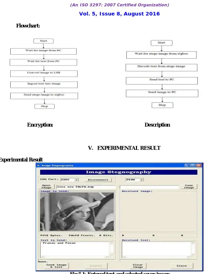
II. SYSTEM MODEL Encryption:
In transmitter section we use power supply, Arm, LCD, personal computer and Zigbee. First in computer we have visual basic 6.0 where we can select any different type of images use in communication and which can be in number or alphabetic we can also see the size of image and then we can write text which is encoded in image using LSB algorithm. This GUI made in Visual basic 6, any image of 16kb consider for stego image. Text massage “Image Steganography” encoded into image and this image send to receiver. It includes LPC2148 ARM Controller. LCD having 16*2 character interfaced to controller. UART0 and UART1 used for serial communication. Here we use UART0 for PC Communication and UART1 for Zigbee interfacing. We send Text + any Image from Pc to Controller. For security, only encryption may not be enough, hence proposed project include combination of both cryptography and Steganography. The encrypted data hide into the image and then image is transmitted in the network. There is some weakness in hiding information in images; that is adversary could easily detect the confidential message, by noticing the noise and clarity of the image's pixels, also by observing the difference between the embedded image and the original one if it is known to him. In the proposed project, we are using an Iris images instead of images that contain faces or natural scenes, because the only feature or data of a person that hackers cannot hack is their biometric features. The obvious choice for an integrated development environment was Keil‟ s mVision4 IDE, because of its excellent debugger and the availability of a free evaluation version. For making GUI, we used visual basic 6.0 software.
Encryption block Decryption block
Step involving in transmission of document:
1. Generate a Secrete key from the Iris image of user using Steganography
2. Use this generated key, and encrypt document as a cipher text, this process of encryption is called cryptography. Generated Key + Document or private file = Encrypted Document (Cryptography)
4. Send this image to its destination though the network using zigbee. 5. Reverse process takes place at the receiver side.
Decryption:
Arm7 has two input i.e. Zigbee model and LCD display. Zigbee receives stego image transmitted by the transmitter, then it sends that image to arm controller. Arm controller receives that stego image from zigbee and decodes text from that image by using the LSB algorithm. It is a reverse process of encryption in which LSBs of the pixels of image are taken to form binary representation of the message text. These are pixel values contains hidden message.
Pixel 1 = (00101101 00011101 11011100) Pixel 2 = (10100110 11000101 00001100) Pixel 3 = (11010010 10101100 01100011)
So the decoded data from image is 11001000, and thus the message is “200”. After decoding by using the UART0 port of ARM controller, that decoded text and image are send to the PC. In PC on the Visual Basic 6.0 GUI we can see the original message and cover image after entering the pass key.
III. THE HARDWARE DESIGN
ARM LPC 2148:
The LPC2148 microcontrollers is based on a 32-bit ARM7TDMI-S CPU with real-time emulation and embedded trace support, that combine microcontroller with embedded high speed flash memory ranging from 32kB to 512kB. A 128-bit wide memory interface and unique accelerator architecture enable 32-128-bit code execution at the maximum clock rate. For critical code size applications, the alternative 16-bit Thumb mode reduces code by more than 30 % with minimal performance penalty. Due to their tiny size and low power consumption, LPC2148 is ideal for applications where miniaturization is a key requirement, such as access control and point-of-sale. Serial communications interfaces ranging from a USB 2.0 Full-speed device, multiple UARTs, SPI, SSP to I2C-bus and on-chip SRAM of 32kB, make these devices very well suited for communication gateways and protocol converters, soft modems, voice recognition and low end imaging, providing both large buffer size and high processing power. Various 32-bit timers, single or dual 10-bit ADC(s), 10-bit DAC, PWM channels and 45 fast GPIO lines with up to nine edge or level sensitive external interrupt pins make these microcontrollers suitable for industrial control and medical systems.
Power supply
Power supply for this circuit is designed by using 9-0 transformer, bridge rectifier, capacitor filter and regulator ICs. Bridge rectifier is designed by using four 1N4007 diodes. The filter circuits are designed by connecting 2200μf capacitor in parallel with output of bridge rectifier. The regulator IC 7805 is used to provide constant 5V dc supply to LCD and regulator IC LM317 is used to provide constant 3.3V supply to ARM processor and all other circuitry.
IV. THE SOFTWARE DETAILS
Visual Basic 6.0
Visual Basic, the fastest and easiest way to create applications for Microsoft Windows. Whether you are an experienced professional or brand new to Windows programming, Visual Basic provides you with a complete set of tools to simplify rapid application development. The "Visual" part refers to the method used to create the graphical user interface (GUI). Rather than writing numerous lines of code to describe the appearance and location of interface elements, you simply add prebuilt objects into place on screen. If you've ever used a drawing program such as Paint, you already have most of the skills necessary to create an effective user interface. The "Basic" part refers to the BASIC (Beginners All-Purpose Symbolic Instruction Code) language, a language used by more programmers than any other language in the history of computing. Visual Basic has evolved from the original BASIC language and now contains several hundred statements, functions, and keywords, many of which relate directly to the Windows GUI. Beginners can create useful applications by learning just a few of the keywords, yet the power of the language allows professionals to accomplish anything that can be accomplished using any other Windows programming language. There are three main steps to creating an application in Visual Basic:
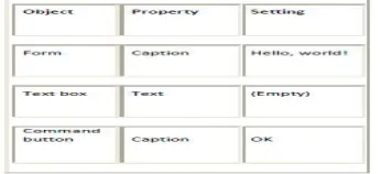
To see how this is done, use the steps in the following procedures to create a simple application that consists of a text box and a command button. When you click the command button, the message "Hello, world!" appears in the text box. Creating the Interface
Forms are the foundation for creating the interface of an application. You can use forms to add windows and dialog boxes to your application. You can also use them as containers for items that are not a visible part of the application's interface. For example, you might have a form in your application that serves as a container for graphics that you plan to display in other forms. The first step in building a Visual Basic application is to create the forms that will be the basis for your application's interface. Then you draw the objects that make up the interface on the forms you create. For this first application, you'll use two controls from the Toolbox.
To draw a control using the Toolbox
1. Click the tool for the control you choose to draw — in this case, the text box. 2. Move the pointer onto your form. The pointer becomes a cross hair.
3. Place the cross hair where you want the upper-left corner of the control.
4. Drag the cross hair until the control is the size you want. (Dragging means holding 5. the left mouse button down while you move an object with the mouse.)
6. Release the mouse button. The control appears on the form. Setting Properties
The next step is to set properties for the objects you've created. The Properties window (Figure 2.5) provides an easy way to set properties for all objects on a form. To open the Properties window, choose the Properties Window command from the View menu, click the Properties Window button on the toolbar, or use the context menu for the control.
The Properties window consists of the following elements:
• Object box — Displays the name of the object for which you can set properties. Click the arrow to the right of the object box to display the list of objects for the current form.
• Sort tabs — Choose between an alphabetic listing of properties or a hierarchical view divided by logical categories, such as those dealing with appearance, fonts, or position.
• Properties list — The left column displays all of the properties for the selected object. You can edit and view settings in the right column.
To set properties from the Properties window
1. From the View menu, choose Properties, or click the Properties button on the toolbar. The Properties window displays the settings for the selected form or control.
2. From the Properties list, select the name of a property.
double-clicking a list item. For the "Hello, world!" example, you'll need to change three property settings. Use the default settings for all other properties.
To open the Code window
• Double-click the form or control for which you choose to write code –or– from the Project Explorer window, select the name of a form or module, and choose the ViewCode button.
Figure 2.6 shows the Code Editor window that appears when you double-click the Command button control, and the events for that command.
Figure 5.6 The Code Editor window
You can choose to display all procedures in the same Code window, or display a single procedure at a time To display all procedures in the same Code window
1. From the Tools menu, select the Options dialog box.
2. On the Editor tab in the Options dialog box, select the check box to the left of Default to Full Module View. The check box to the left of Procedure Separator adds or removes a separator line between procedures –or– clicks the Full ModuleView button in the lower left corner of the Code Editor window.
To display one procedure at a time in the Code window 1. From the Tools menu, select the Options dialog box.
2. On the Editor tab in the Options dialog box, clear the check box to the left of Default to Full Module View –or– click the Procedure View button in the lower left corner of the Code Editor window. The Code window includes the following elements:
• Object list box — Displays the name of the selected object. Click the arrow to the right of the list box to display a list of all objects associated with the form.
• Procedure list box — Lists the procedures, or events, for an object. The box displays the name of the selected procedure — in this case, Click. Choose the arrow to the right of the box to display all the procedures for the object. Creating Event Procedures
Code in a Visual Basic application is divided into smaller blocks called procedures. An event procedure, such as those you'll create here, contains code that is executed when an event occurs (such as when a user clicks a button). An event procedure for a control combines the control's actual name (specified in the Name property), an underscore (_), and the event name. For example, if you want a command button named Command1 to invoke an event procedure when it is clicked, use the procedure Command1_Click.
For More Information For information on creating other types of procedures, see "Introduction to Procedures" in "Programming Fundamentals."
Running the Application
Flowchart:
Encryption: Description
V. EXPERIMENTAL RESULT
Experimental Result
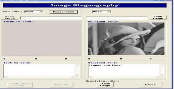
Fig 5.1: Entered text and selected cover image
We design GUI for image Steganography. This GUI design take place in Visual Basic 6.0 which is very simple and user friendly software to design GUI. In this GUI, we can take an image file which you want to use in communication. We can also see the size of image. Then we can write text which is encoded in image. Fig 5.1 showing that the cover image is selected and text to be send is entered. Then by pressing send image and text image and text are downloaded into ARM processor
as shown in fig 5.2.
Fig 5.2 Downloading image and text into the ARM7
Fig 5.3 Encoding text and sending using zigbee
Then at receiving circuit that text and image is received by zigbee (as shown in fig 5.5) and then decoded text from stego image and image are sent to the PC .
Fig 5.4 Receiving done
The image and text received can be viewed at the VB GUI as shown in fig 6.6 and the status of LCD after image and text is received completely is shown in fig 6.7
VI. CONCLUSION
It is possible to send text message from any image using LSB algorithm. It can be used to send data on network secure. In our project we have successfully done image Steganography, where we hide data inside the carrier image using LSB algorithm at receiver side. After receiving the stego image at receiver side we can also get the data. the image Steganography can be done in the gray scale image and also in colour image. A software implementation of a Steganography scheme provides the benefits of flexibility, speed of implementation, and lower cost over time.
REFERENCES
[1] Ms. Pallavi Hemant Dixit,” Arm Implementation of LSB Algorithm of Steganography” Submission, Shivaji University, Kolhapur, Maharashtra, India.
[2] Mr. Vijay Kumar Sharma,” A Steganography algorithm for hiding image in image by improved lsb substitution by minimizes detection”
Submission, Arya college of Engineering & IT, Jaipur, Rajasthan (India).
[3] Ms. Neha Aggarwal,” Enhanced Least Significant Bit algorithm For Image Steganography” Submission, Department of computer science, Manav Rachna Collegeof Engineering Faridabad, India.
[4] Sim Hiew Moi, Nazeema Binti Abdul Rahim,Puteh Saad, Pang Li Sim, Zalmiyah Zakaria, Subariah Ibrahim,“Iris Biometric Cryptography for Identity Document”, 2009 International Conference of Soft Computing and Pattern Recognition.
[5] Sujay Narayana1and Gaurav Prasad” Two New Approaches For Secured Image Steganography Using Cryptographic Techniques And Type Conversions” Signal &Image Processing: An International Journal (SIPIJ) Vol.1, No.2, December 2010
[6] Hassan Mathkour , Batool Al-Sadoon, Ameur Touir ” A New Image Steganography Technique”
[7] Mamta Juneja 1, Parvinder Singh Sandhu2 “Designing of Robust Image Steganography Technique Based on LSB Insertion and Encryption” 2009 International Conference onAdvances in Recent Technologies in Communication and Computing.
[8] V.V.Satyanrayanarayana Tallapragada, Dr. E.G.Rajan, “Multilevel Network Security Based on Iris Biometric” 2010 International Conference on Advances in Computer Engineering.
BIOGRAPHY
Prof. Pradip S. Bhendwade received the M. Tech in Electronics and currently working as Assistant Professor in Ashokrao Mane Group of Institute, Vathar, and Kolhapur. His area of specialization is Embedded Systems, Microprocessor and Microcontroller, Control System.