Implementation of a Wind/PV Hybrid System
using MATLAB/Simulink
Anjali Rana
1, Mohammad Ilyas
2M. Tech Student [Power Systems], Dept. of EEE, Al-Flah University, Faridabad, Haryana, India1
Assistant Professor, Dept. of EEE, Al-Flah University, Faridabad, Haryana, India2
ABSTRACT: Due to development in renewable energy technologies and continued rise in prices of petroleum products hybrid renewable energy systems are gaining more importance for supplying the power to meet the today’s increasing energy demands either as a stand-alone system or as a grid connected system. In this paper a model of grid connected hybrid system consists of wind and solar (photovoltaic) system is studied and implemented in Simulink. The proposed system consists of a wind turbine, a PV solar cell array, boost converter, and an inverter to convert DC to AC of grid frequency. A relative study of hybrid model solar/wind system has been made. This Paper illustrates wind and solar hybrid system for supplying electricity to the power grid.
KEYWORDS: Hybrid, Wind turbine, PV cell, Power grid, Boost converter. I.INTRODUCTION
In the last few years, because of high depletion of conventional energy resources and environment concerns, the renewable energy resources are becoming more important all over the world. Among different renewable energy sources, wind and solar energy sources are most promising. Since the oil crisis of the early 1970s, the utilization of solar and wind power has become increasingly noteworthy, popular and cost-effective. But the main disadvantage of solar and wind energy system is that it depends on seasonal variation and it is unpredictable in nature. As both wind and solar energy sources are not consistent and non-stable in nature. A hybrid system of wind and PV power sources provides a stable form of power generation. Hybrid energy systems are cost effective energy solutions with high reliability and power quality. Individual photovoltaic (PV) or wind energy system, do not generate utilizable energy for a large portion of time during the year. This is because of dependency on variable sunshine hours in PV system and on relatively high cut-in wind speeds. In this paper individual modeling of PV and wind energy system is done and studied in Matlab/Simulink software. A Hybrid model of PV and Wind system is also implemented and studied.
II.MATHEMATICAL MODELING OF SOLAR PV CELL
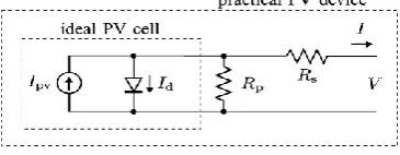
Solar (PV) systems capture the sunlight and directly convert it into electricity. Photovoltaic (PV) cell is the basic element of a PV system. A photovoltaic cell is a semiconductor diode whose p-n junction is open to the light. When sunlight strikes the solar cell junction, free electrons and holes are generated and a current is delivered to the load when it is short circuited. A grouping of PV cells forms a solar panel. To obtain large output voltage solar panels are formed by connecting PV cells in series and to achieve large output current cells are connected in parallel. Fig.1 shows the equivalent circuit of a PV cell.
Fig. 1Equivalent circuit of a PV cell
Where Ipv, cell = incident light current (which is directly proportional to the sun radiation), Id = Shockley diode equation
Io, cell = reverse saturation or leakage current of the diode q = electron charge (1.60217646 * 10-19 C)
k = Boltzmann constant (1.3806503 * 10-23 J/K) T = temperature of the p-n junction
a = diode ideality constant
The equation (1) of PV cell does not show the I-V characteristics of a practical PV array. To observe PV array characteristics inclusion of some additional parameters to the equation (1) is necessary. Hence the equation is represented as: Rp I Rs V 1 a Vt I Rs V exp Io Ipv
I
(2)In this equation Vt is the thermal voltage and Rs & Rp are the equivalent series and parallel resistances.Equation (2) describes the single diode model shown in Fig.1.
The incident light current of PV cell depends on solar irradiation and is greatly affected by the temperature can be expressed as:
Gn G KIΔI n Ipv,Ipv
(3)
Where Ipv, n = incident light current at nominal conditions (250 C and 1000W/m2) ∆T = T - Tn (difference between actual and nominal temp)
G and Gn is the actual and nominal irradiation respectively
The reverse saturation current Io also affects by temperature which is represented as:
T 1 n T 1 ak qEg exp 3 T n T IoIo (4)
Where Eg = band gap energy of the semiconductor Io, n = nominal saturation current
Table 1 shows the electrical parameters that are considered for designing the PV array with ambient temperature (Tamb)
of
28°C and solar insolation of 900w/m2.Table.1 Electrical parameters for PV array
S. No. Parameters Values
1. Voltage at Maximum power 75.4 V 2. Current at Maximum power 2.93 A 3. Open circuit voltage 96.8 V 4. Short circuit current 3.02 A 5. Reference Temperature 60°C
III.STEP BY STEP SIMULINK MODELING OF SOLAR PV MODULE
PV cell converts the solar radiation directly into electricity with both I-V and P-V output characteristics. Based on the above mathematical equations simulink modeling of PV module is done in following steps:
A. STEP I
Fig. 2 Subsystem to calculate I SC’
The below figure shows the circuit of the above subsystem.
Fig. 3 Circuit of subsystem to calculate ISC’
B. STEP II
A subsystem is shown in fig. 4.This model calculates the open circuit voltage (Voc’) with inputs of S = 900w/m2, Tamb=28°C, Voc’ = 2.93A, Tref = 60°C.
Fig. 4 Subsystem 1 to calculate Voc’
The below figure shows the circuit of the above subsystem.
Fig. 5 Circuit of subsystem 1 to calculate Voc ’
C. STEP III
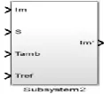
A subsystem to calculate the current at Maximum power (Im’) with inputs of S = 900w/m2, Tamb=28°C, Im = 2.93A, Tref = 60°C is shown in fig.6.
Fig. 6 subsystem 2 to calculate Im’
Fig.7 Circuit of subsystem 2 to calculate Im’
D. STEP IV A subsystem to calculate the Voltage at Maximum power (Vm
’
) with inputs of S = 900w/m2, Tamb=28°C, Vm = 75.4V Tref = 60°C is shown in fig.8.
Fig. 8 Subsystem 3 to calculate Vm’
The below figure shows the circuit of the above subsystem.
Fig. 9 Circuit of subsystem 3 to calculate Vm’
E. STEP V
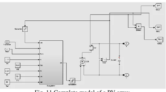
A complete connected model of subsystems is shown in fig.10. In this figure all subsystems are interconnected to calculate the incident light current Ipv.
Fig.10 Interconnection of all subsystems
Fig. 11 Complete model of a PV array
IV.MODELLING OF WIND TURBINE
Wind energy is an environment friendly and endless source. Therefore, a wind energy generation system may be one of the promising sources of alternative energy for the future demand.Wind turbines convert the kinetic energy of wind into mechanical energy. The magnitude of this converted mechanical energy depends on the air density and the wind velocity. The wind power (Pm) that is developed by the turbine is given by the equation:
3 Pm
C
,
Aw
2
1
P
(5)Where CP = performance coefficient of turbine ρ = air density (kg/m3)
A = area of turbine blades (m3) w = wind velocity (m/sec)
λ = tip speed ratio of the rotor blade tip speed to wind speed β = blade pitch angle (deg)
The coefficient CP is the fraction of kinetic energy which is converted by wind turbine into mechanical energy. It is related to the tip speed ratio (λ).
Wind turbine output torque (Tm) can be calculated using equation:
AC
w
2
1
T
m p (6)Fig.12 shows the ideal power curve of the wind turbine showing different operating regions with three different wind speeds i.e. cut-in wind speed, rated wind speed and cut-out wind speed.
Fig. 12 Ideal power curve of wind turbine
Fig. 13 Simulink model of wind turbine
This wind turbine is connected to a three phase synchronous generator which converts this mechanical power into electrical power. A single turbine is used in this work.
IV. MODELING OF HYBRID PV/WIND SYSTEM
A grouping of Wind and PV energy system into a hybrid generation system may increase their efficiency by increasing their overall energy output, by reducing energy storage requirement. This makes system less costly and more reliable as compared to individual energy system.
A hybrid system of wind and PV connected to grid is simulated. It consists of a three phase converter with PWM generator and voltage source converter which convert DC to AC of grid frequency. A simulink model of hybrid system is shown in fig. 14.
Fig. 14 Simulink model of wind/PV hybrid system
A complete simulink model of grid connected Wind/PV hybrid system is shown in figure given below.
Fig. 15 Complete simulink model of grid connected wind/PV hybrid system
V.RESULT AND DISCUSSION
Fig.16 DC output voltage of wind system
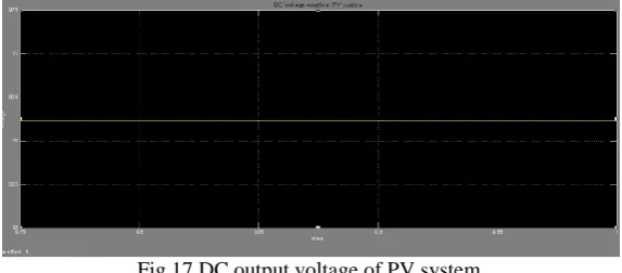
The below figure is the waveform of DC output voltage of simulated PV energy system.
Fig.17 DC output voltage of PV system
By combining the PV and Wind energy system, a hybrid energy system has been simulated. This simulated hybrid model generates a DC voltage. The below figure shows the waveform of DC output voltage of simulated wind/PV hybrid system.
Fig. 18 DC output voltage of Wind/PV hybrid system
Individual modelling and simulation study of Wind and PV system has been carried out in Matlab/simulink. Then a hybrid model has been simulated by combining these energy resources with the help of converter and voltage regulator. The simulation result of implemented hybrid system shows the generated output voltages which can be supplied to the grid. This hybrid system is more reliable as compared to single energy system.
REFERENCES
[1] M.K. Deshmukh, S.S Deshmukh, ―Modeling of hybrid renewable energy systems,‖ Renewable & Sustainable energy reviews, pp. 235-249, 12
(2008).
[2] M.A. Elhadiadly, ―Performance evaluation of hybrid (wind/solar/diesel) power systems,‖ Renewable energy, pp.401-413, 26 (2002).
[3] Juan Manuel, Carrasco, Jan T. Bialasiewicz, Ramon C.Portillo Guisado, Jose Ignaciao leon, ―Power electronic systems for the grid integration
of renewable energy resources: A survey,‖ IEEE transactions on Industrial electronics, vol. 53, No. 4,Aug 2006.
[4] Marcelo Gradella Villalva, Jonas Rafael Gazoli, and Ernesto Ruppert Filho, ―Comprehensive Approach to Modeling and simulation of PV
arrays,‖ IEEE Transactions on Power Electronics, Vol. 24, No. 5, pp. 1198-1207, May 2009.
[5] Mohamed A. Eltawil, Zhengming Zhao, ―Grid-connected photovoltaic power systems: Technical and potential problems—A review,‖
Renewable and Sustainable Energy Reviews, pp. 112–129, 14 (2010).
[6] K. Shivarama Krishna, B. Murali Mohan, and Dr. M. Padma Lalitha, ―Dynamic modeling & control of grid connected hybrid wind/PV
generation system,‖ IJERD, vol.10, Issue 5, pp. 01-12, May 2014.
[7] Abdullah M.A., Yatim A.H.M., Tan C.W., Saidur R., ―A review of maximum power point tracking algorithms for wind energy systems,‖
Renewable and Sustainable Energy Reviews, pp.3220– 3227, 16 (2012).
[8] Md. Aminul Islam, Adel Merabet, Rachid Beguenane, Hussein Ibrahim, ―Power Management Strategy for Solar-Wind-Diesel standalone
Hybrid Energy Systems,‖ International Journal of Electrical, Computer, Electronics and Communication Engineering ,Vol.8, issue 6, 2014.
[9] Boucetta. Abdallah, Labed. Djamel, ―Modeling and Control of a Wind/PV Hybrid System Grid-connected,‖ International Journal of Scientific
& Engineering Research, Volume 4, Issue 8, August 2013.
BIOGRAPHY
Anjali Rana was born on 28th June 1989 in Delhi, India. She received the graduation degree in Electrical and Electronics Engineering in 2011, from UPTU Lucknow. Currently she is pursuing Master’s in Power Systems from MDU Haryana. Her research interests include power generation using renewable energy resources and power quality.