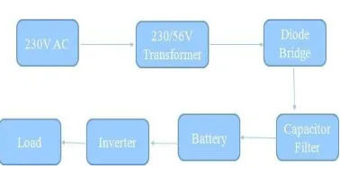
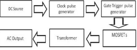
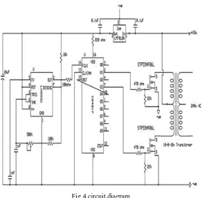
Battery and Inverter System for V2G Based Solar Electric Vehicle
Full text
Figure

Related documents
- Engine protections: low fuel level, low oil pressure, high engine temperature, - Genset protection: under/over voltage, overload, under/over battery voltage,
information with non-social cognitive theory-based health information presented to overweight or obese women, there is a significant difference in symptom count posttest scores
This page provides information on the input battery voltage, the inverter output voltage and power, whether the AC output is provided by the inverter or an external AC source
The authors suggest understanding the corporation’s IC protection as a set of systematic focused measures taken by management (or authorized persons) to prevent and neutralize the
Nofemele vs Road Accident Fund (Wheeldon Rushmere & Cole: Mr. Brody) (Netteltons: Mr... Weitsz vs Minister of Safety & Security & 3 others (NN Dullabh & Co.:
Michigan Economic Development Corporation (“MEDC”) staff recommends the Michigan Strategic Fund (“MSF”) allocate $11,000,000 of Community Development Block Grant
In electronic circuits, power dissipations are expressed by a mean value, whereas the actual.. situation is generally a
This study is about determination of the starch concentration in four Vitis vinifera varieties: Vranec and Smederevka (subconvarietas balcanica Negr.) and Cabernet sauvignon
