Modelling and Level Control of a Three Tank
Hydraulic System
Lekshmipriya J
Assistant professor, Dept. of AE&I, Mount Zion College of Engineering, Pathanamthitta, Kerala, India
ABSTRACTThe multi tank system relates to liquid level control problems commonly occurring in industrial storage tanks. For the most common liquid level systems the main objective of the control is to reach and stabilize the level in the tank by an adjustment of the pump operation and/or the valve settings. These control problems can be solved by a number of level control strategies. In this work a three tank hydraulic system is chosen, which consists of some specifications. Initially the mathematical modelling of the system was done giving preference to the system specifications, then controlled the system using the conventional PID controller ,the level of liquid in the tanks are controlled. The controller tuning was done by Zeigler Nichols method. Also this work shows the results while using an MPC.
KEYWORDS: Three tank system, PID controller, Zeigler Nichols method, MIMO system, cylindrical tanks, MATLAB/SIMULINK, MPC
I. INTRODUCTION
In most of the industrial applications the liquid level control is of great importance, especially in petrochemical industries& food processing. The quality of the final product depends on the accuracy of the level controller. In industries the level control systems with large dead time are difficult to control. The aim of the controller is to maintain the set point and be able to adopt a new set point values automatically. In process control , the basic objective is to regulate the value of some quantity. To regulate means to maintain that quantity at some desired value regardless of external influences. The desired value is called reference value.
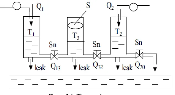
In this work, a three tank liquid level system is selected which consist of three cylindrical tanks, three sensors, two pumps, two interconnected valves, one output valve and three leakage valves. The pump P1 controls the inflow to tank T1 while the pump P2 controls the liquid inflow to tank T2. There is no pump connected to the middle tank T3. Here the system is controlled with the conventional PID controller and also with Model Predictive Controller.
The PID (Proportional Integral Derivative) control is a widely used approach for designing a simple feedback control system, wherein three constants are used to weight the effect of error, the integral of the error and the derivative of the error. In a PID controller, the error signal is used to generate the proportional, integral and derivative actions, with the resulting signals weighted and summed to form the control signal which is applied to the system.The prime factor which differentiate MPC (Model Predictive Controller) from most other control strategies is the receding horizon principle .At each sampling instant, an MPC controller solves, a finite horizon optimal control problem. Only the first value of the resulting optimal control variable solution is applied to the plant, and the rest is discarded. The same process is repeated at each sampling instant ,and the prediction horizon is shifted forward one step. Thus the name receding horizon control.
II.SYSTEM MODEL AND ASSUMPTIONS
the tank 3 can only gain liquid by coupling effect from tank 1 and 2. The circle is closed. The open-loop three tank system is stable. Its response time is comparatively long and main control problem is locating at the desired state at a shorter time.
Figure 2.1: Three-tank system.
According to the substance balance, the three tank system can be described by the following differential equations:
(2.1)
(2.2)
(2.3)
Where Qij is the flow rate from i to j andis the flow rate from tank 2 to the reservoir.
The dynamics of the system is given by
( 2.4)
(2.5)
The process is nonlinear, a linearized model must be derived. Introducing Dx = x−x0, Du = u−u0 and Dy = y−y0, we obtain (2.6)
20 32 2 2
Q
Q
Q
dt
dh
S
32 13 3
Q
Q
dt
dh
S
20 32 2 2
Q
Q
Q
dt
dh
S
Bu
Ax
x
(2.7)
(2.8)
III. SIMULATION RESULTS AND DISCUSSION
In this session mainly the simulation diagram and the results obtained after controlling the selected three tank liquid level system using the PID controller and model predictive controller is given, then the results are compared. MATLAB/SIMULINK software has been used for simulation studies.
A. WITH PID CONTROLLER
Here PID controller is used to control the liquid level in the three tanks T1, T2 and T3.
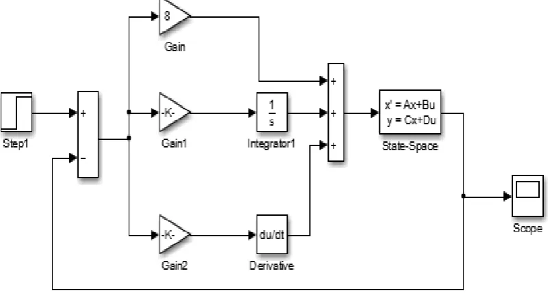
Figure 3.1: Simulink model of the system with PID controller
Here it is controlling the liquid level in the two side tanks T1 and T2, the heights h1 and h2 are controlled, using Proportional Integral Derivative controller and controller tuning is done by Zeigler Nichols method. The Simulink diagram for the closed loop system is given in figure 4.1 where Kp = 10, Ki = 1 and Kd = 18
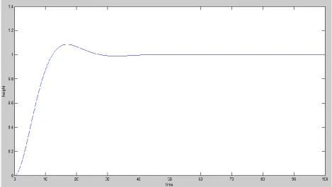
Figure 3.2: Closed loop response of system with PID Controller
Here the liquid level in the middle tank is controlled using PID controller. From the closed loop response it is evident that the system settles at 45s and the peak time is 18s ,where Kp = 8, Ki = .67 and Kd = 23.6
B. USING MODEL PREDITIVE CONTROLLER
Figure 3.4: Simulation diagram for the system with mpc.
The MPC Controller block takes as its inputs a vector signal consisting of the measured outputs of the plant and the reference value. Its output is a vector signal consisting of the control signal u, and the internal state estimation of the controller.
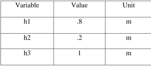
The process consists three tanks, organized in pairs , where water from the two tanks flows into the middle tank. Pumps are used to pour water into the left tank and the right tank. The control variables are the pump voltages. Let the states of the system be defined by the water levels of the tanks (expressed in m) h1, h2 and h3 respectively. The maximum level of each tank is 1m.The stationary operating conditions, are given in Table 3.1. The objective of the control system is to control, independently, the level of the three tanks, while preventing overflow in any of the three tanks. Also, the operation of the pumps is limited to 0 to 10 V. We notice that among this the stationary level of the second tank is close to the maximum level.
Table3.1:- Initial values corresponding to valve position
Variable
Value
Unit
h1
.8
m
h2
.2
m
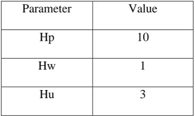
In Table 3.2, the controller parameters used in the simulations are summarized. The choice of prediction and control horizons have been made considering the time constants of the system. Too short horizons may cause instability.
Table 3.2 MPC controller parameters for simulation
Parameter
Value
Hp
10
Hw
1
Hu
3
Figure 3.5 shows the result obtained after controlling the selected three tank liquid level system with model predictive controller .Here it is tried to control the three level of liquid in the three tanks, which are T1, T2 and the middle tank T3.
Figure 3.5: Closed loop response of the system with MPC.
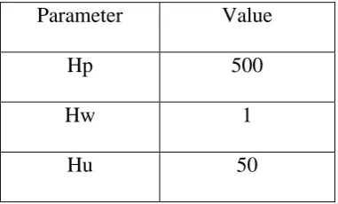
Table 3.3 MPC controller parameters for simulation
Parameter
Value
Hp
500
Hw
1
Hu
50
Figure 3.6 shows the result obtained after controlling the selected three tank liquid level system with model predictive controller but here the response time is slightly larger as compared to the lower values of prediction horizon and control horizon and shows that slight change of these values wont affects the controller performance much.
Figure 3.6 Closed loop response of the system with mpc
IV. CONCLUSION
From the analysis of the responses obtained we can see that,
MPC is very well suited for multivariable control actions, as loop interaction takes place between manipulated variable and control variable and from the study and simulation results we can see that the MPC controller is much effective for this MIMO system than the conventional controllers. By analysing the result obtained while controlling the liquid levels using MPC, it seems that the rise time, peak time, settling time and also the peak overshoot is decreased. Thus in common we can say that Model Predictive Control (MPC) refers to a class of computer control algorithms in which a dynamic model of process is used to predict andoptimize its performance.
REFERENCES
[1] K-H.Johansson: The Quadruple-Tank Process: A Multivariable Process with an Adjustable Zero, IEEE Transaction on control systems technology, Vol-35, pp:57-65,2000.
[2] L.Magni,G.De Nicolao, L.Magnani, and R.Scattolini: A Stabilizing Model Based PredictiveControl Algorithm for Nonlinear Systems, Automatica ,Vol- 37:pp1351-1362,2001.
[3] B. W. Bequette, Nonlinear control of chemical processes: a review. Ind. Engng Chem , Vol. 30, pp.1391 – 1413,1993.
[4] G. Gattu and Zafiriou , Nonlinear quadratic dynamic matrix control with state estimation. Ind. Engng Chem. Res. 31, , pp. 1096 – 1104,1992. [5] A. L. Cervantes, O. E. Agamennoni and J. L. Figueroa, Use of wiener nonlinear MPC to control a CSTR with multiple steady state, Latin American Applied Research, 33, , pp. 149 – 154,2003.
[6] M. A. Henson, Nonlinear model predictive control: current status and future directions, Computer and chemical engineering,Vol 23, , pp. 187 –192,1998.
[7] M. Aldeen, and R. Sharma,“Robust Detection of Faults in Frequency Control Loops,” IEEE Transactions on Power Systems, vol. 22, no. 1, pp: 413–422,2007.
[8] Alireza Yazdizadeh , Mohammad Hossein Ramezani, Ehsan Hamedrahmat “Decentralized load frequency control using a new robust optimal MISO PID controller” Electrical Power and Energy Systems,Vol-35, pp:57-65,2012.
[9] A. Khodabakhshian, M. Edrisi “A new robust PID load frequency controller” Control Engineering Practice, Vol-16, pp: 1069-1080,2008. [10] J. Prakash and K. Srinivasan, Design of nonlinear PID controller and nonlinear model predictive controller for a continuous stirred tank reactor, ISA Transaction 48, pp. 273 – 282,2009.
[11] Kucera, V., “Stochastic Multivariable Control: a Polynomial approach”, IEEE Trans. of Automatic Control, vol. 5, , pp. 913 –919,1980. [12] Kucera, V., Analysis and Design of Discrete Linear Control Systems. Academia, Prague,1991.
[13] Bitmead R. R., Gevers M., Hertz, V., Adaptive Optimal Control. The Thinking Man’s GPC. Prentice Hall, Englewood Cliffs, New Persey,1990.