Advanced power control strategy in grid connected PV
systems for constant power generation
S.R.S.Akhila & Y.Manasa
Abstract
- Each solar cell has avoltage-current (V-I) characteristic reflecting its response to both temperature and the incident light level. This is generally achieved using the algorithmic method for continuous maximum power point tracking (MPPT) i.e. the product between Voltage and Current shall be maximum. This can also ensure a fast and smooth transition between maximum power point tracking and Constant Power Generation (CPG). Regardless of the solar irradiance levels, high-performance and stable operation are always achieved by the proposed control strategy. It can regulate the PV output power according to any set-point, and force the PV systems to operate at the left side of the maximum power point without stability problems. The main goal of this paper is to implement the MPPT algorithm in advanced technique like fuzzy logic and determine if the algorithm implemented by fuzzy logic is optimal for controlling MPPT in order to establish the maximum power generated by the PV systems.
Index Terms
-Maximum Power Point Tracking, PV Systems, Power Control,Converters, Constant Power
Generation.
I.
INTRODUCTION
DUE to the world energy crisis and environmental problems caused by conventional power generation, renewable
Now-a-days, Maximum power point tracking technique has become compulsory for grid-connected PV systems for
maximum power yield. But for more power generation we need to install more PV systems, which results in high cost factor, so the easy and better way to generate maximum power is nothing but modifying the MPPT technique at the PV inverter level. So that we can yield constant power generation (CPG)
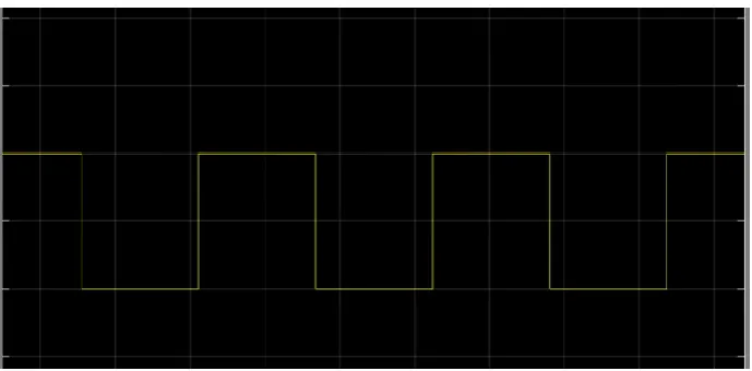
Fig: MPPT Mode during 1,3,5 & CPG mode during 2,4.
Among all algorithms CPG based on Perturb & Observe algorithm was introduced in single stage PV configuration. But controlling operation of that algorithm is limit only to the right side of the Maximum power point (MPP) of the PV arrays because of its single stage configuration. Because of this drawback the complete system performance gets decreased when there occurs any sudden change in its irradiance conditions. Even we also experience open-circuit condition .So; we go for two stage grid -connected PV system configuration in order to tackle the above issues and achieve stability factor.[5]-[9]
Fig: Stability issues of conventional CPG algorithm, when operating point is located at right side of MPP.
II.
Conventional CPG
Algorithm
A.
System Configuration
The Basic configuration of the two stage grid connected PV system and its control structure is discussed in detail and shown below. Its control is implemented in the boost converter and the inverter is realized using a cascaded control where the DC-Link is maintained constant throughout the configuration. The PV Systems operate at the unity power point which means that only the active power is injected to the grid.
to ensure smooth power delivery to the grid.[10]
B.
Control structure
Fig: Control structure of Perturb & Observe algorithm based on the CPG Technique where Proportional Integral (PI) is adopted.
C.
Issues of P&O-CPG Algorithm
The P&O-CPG method has satisfied performance under the slow changing irradiance conditions i.e., during a clear day, when the operating point is at the left side of the MPP. But when the irradiance fluctuates there results in several power losses and overshoots .We can analyse these overshoots and power losses using operational trajectory of the PV systems.
Fig: Operating trajectory of the algorithm during fast changing irradiance condition.
These power losses and overshoots can be minimized by using advanced technique like simulink based on fuzzy logic technique. Even the system performance can also be developed using this technique. Simultaneously the Simulink results are mentioned below in detail.
III. FUZZZY LOGIC
Recently, FLC are introduced for MPPT in the PV system. These controllers are robust and advantageous as in their design procedure exact model information is not required. [11]. The main parts of a fuzzy logic controller are fuzzification,
inference, rule base and
defuzzification, are shown in figure.
IV.
Simulation Results
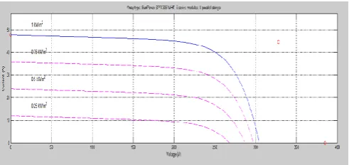
Fig: V-I Characteristics of PV module
Fig : P-V Characteristics of PV module
Fig: P-V Characteristics of PV Array
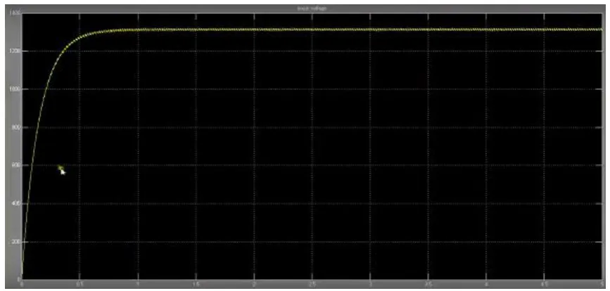
Fig: Grid voltage and currents
Fig : Constant power generation in CPG algorithm.
Fig: Constant power generation using fuzzy logic
V.
CONCLUSION
A high performance active power control scheme for maximum feed in power has been developed in this paper. This proposed paper provides a solution to operate the PV system at the left side of
improve the system accuracy and also the system performance. It also minimizes the power losses and also minimizes the overshoots.
REFERENCES
review,” Renewable Sustainable Energy Rev., vol. 14, no. 1, pp. 506–511, 2010. [2] M. Bragard, N. Soltau, S. Thomas, and R. W. De Doncker, “The balance of renewable sources and user demands in grids: Power electronics for modular battery energy storage systems,” IEEE Trans. Power Electron., vol. 25, no. 12, pp. 3049–3056, Dec. 2010.
[3] A. Yazdani and P. P. Dash, “A control methodology and characterization of dynamics for a photovoltaic (PV) system interfaced with a distribution network,”
IEEE Trans. Power Del., vol. 24, no. 3, pp. 1538–1551, Jul.2009.
[4] A. Yazdani, A. R. Di Fazio, H. Ghoddami, M. Russo, M. Kazerani, J. Jatskevich, K. Strunz, S. Leva, and J. A. Martinez, “Modeling guidelines and a benchmark for power system simulation studies of three-phase single-stage photovoltaic systems,” IEEE Trans. Power Del., vol. 26, no. 2, pp. 1247–1264, Apr. 2011.
[5] M. A. Abdullah, A. H. M. Yatim, C. W. Tan, and R. Saidur, “A review of maximum power point tracking algorithms for wind energy systems,” Renewable Sustainable Energy Rev., vol. 16, no. 5, pp. 3220–3227, Jun. 2012.
[6] S. Burusteta, J. Poe, S. Ceballos, I. Marino, and J. A. Alzola, “Capacitor voltage balance limits in a multilevel-converter-based energy storage system,” in
Proc. 14th Eur. Conf. Power Electron. Appl., Aug./Sep. 2011, pp. 1–9.
[7] L. Xinchun, Shan Gao, J. Li, H. Lei, and Y. Kang, “A new control strategy to balance neutral-point voltage in three-level NPC inverter,” in Proc. IEEE 8th Int.Conf. Power Electron.ECCEAsia, May/Jun.
[8] J. Rodriguez, S. Bernet, P. K. Steimer, and I. E. Lizama, “A survey on neutral-point-clamped inverters,” IEEE Trans. Ind. Electron., vol. 57, no. 7, pp. 2219–2230, Jul. 2010.
[9] A. Lewicki, Z. Krzeminski, and H. Abu-Rub, “Space-vector pulse width modulation for three-level npc converter with the neutral point voltage control,”
IEEE Trans. Ind. Electron., vol. 58, no. 11, pp. 5076–5086, Nov. 2011.
[10] J. Pou, D. Boroyevich, and R. Pindado, “Effects of imbalances and nonlinear loads on the voltage balance of a neutral-point-clamped inverter,” IEEE Trans. Power Electron., vol. 20, no. 1, pp. 123–131, Jan. 2005.
[11] Z. Huibin, S. Jon Finney, A. Massoud, and B. W. Williams, “An SVM algorithm to balance the capacitor voltages of the three-level npc active power filter,”
IEEE Trans. Power Electron., vol. 23, no. 6, pp. 2694–2702, Nov. 2008.
S.R.S.Akhila is persuing her M.Tech in Electrical Power Systems at JNTU College of Engineering & Technology Anantapuramu , Andhra Pradesh, India.
Y.Manasa is presently working as a lecturer at JNTU College of Engineering & Technology,Anantapuramu,Andhra