Sub-query Fragmentation for Query Analysis and
Data Caching in the Distributed Environment
Santhilata Kuppili Venkata
∗1and Katarzyna Musial
†21
The National Archives, London, United Kingdom
2
Advanced Analytics Institute, School of Computer Science, University
of Technology Sydney, Sydney, Australia
Abstract
The world of query-response systems heavily depends on the cloud storage solutions, distributed data transfers and locality of users etc. When data stores and users are distributed geographically, it is essential to organize distributed data cache points at ideal locations to minimize data transfers. This leads to the question,whatdata to cache inwhich location. To answer this, we are devel-oping an adaptive distributed data caching framework that can identify suitable data chunks to cache and move across a network of community cache locations. This paper details the first step of the process: the sub-query fragmentation tech-nique to fragment data into portable objects. Evaluation suggests that sub-query fragments enable distributed learning methods to understand query patterns and association between sub-queries. The sub-query objects can be modelled easily as input dataset to implement machine learning models to assist cache mainte-nance.
Keywords:Query analysis, distributed data caching, query modeling
1
Introduction
Nowadays, it is common for organizations to store their data distributed geographically such as cloud storage systems. Organizations provide a query-response layer over the data storage and hide the location details from users. However, when the responses to user queries (requests) are involved with heavy data transfers, the query analysis provide deep insights into the data placement plans. Clouds and hybrid cloud storage systems are in need of newer technologies to tackle the data placement problem. If the user queries request for a specific piece of data repeatedly, the data item becomes
∗[email protected] - Corresponding author †[email protected]
a candidate for caching. Since users are also distributed, a data item can be requested from multiple locations. The data item may be requested repeatedly from various locations from different locations. We need to analyse the patterns of these queries to understand the request flow for a cached data item.
In order to answer the above problem, we have developed CommCache - a dis-tributed adaptive community caching framework to aid disdis-tributed data storage sys-tems. CommCache accepts consists of a central query analyser to accept user queries and fragments them to model them into patterns. Queries are fragmented using sub-query fragmentation technique. In this paper, the sub-sub-query fragmentation technique is detailed to identify the most ideal query fragment for data caching. The sub-queries can be modelled as objects to be placed across network of caches.
Here is a scenario to understand the CommCache environment. It is common for communities of users from different parts of the world to collaborate on projects and access common data stores. It is observed that often their requests to retrieve data partially overlap. It means, it is not necessary that the entire data related to a particular query should be cached. Only a part of the query may be is in common with another query. It follows that certain data segments are frequently needed across different locations at different times, as specified by the data flow pipeline. We utilise this feature to propose sub-query fragmentation for distributed data caching.
When a sub-query qi of a queryQis a part of several queries, thenqi becomes an
good candidate for caching. Ideally eachqi inQis stored on a cache unit at a location
near the data usage. In our research, we aim to achieve the following: (1) model data component(s) as independent distributed objects, (2) define query structures to represent the most frequently searched data and location of the data usage and (3) describe operations for distributed search and retrieval of the cached data. In this paper, we present formal definitions and modeling of data segments and evaluation of the model under various simulated conditions.
2
Background & Related Work
The concept of data caching to reduce response time and volumes of data transfers is highly researched in the past. Multiple experiments with a variety of cache grains are available in the literature. Page caching and tuple caching are and the most widely used approaches to cache results of the query. Page caching caches a collection of index and data pages [8]. Tuple caching caches collections of tuples [8, 9]. Though of tuple caching caches accurate data, the maintenance overhead makes tuple caching a non-feasible technique to implement in distributed applications. Attribute caching is even a fine grained model: it stores data [10] at the attribute level of a table. Unless attribute caches are highly specific to an application, they may not be used for larger tables. Both tuple and attribute caches have very high maintenance for general applications. None of these caching methods is suitable for distributed caching for the overhead to maintain data from multiple databases.
Chen et al. [11] were the pioneers of query result caching and query matching. In their work, authors proposed about intermediate results to cache. They have defined a directed graph whose nodes reference to base relations and cached temporaries and edges represent derivation paths. Their graph representation helps the direction of query fragments and the path to process the data.
and merge it with the existing cache entry. It may include joining the cache results with a new table, extending ranges ofWHERE clauses and other constraints. The system must take care such that the remainder query and the merging of the remainder query with the cache entry do not cost more than the original new query. However, if the construction of the remainder query is successful, the semantic caching produces little overhead and reduces response time and network overhead [12]. Semantic caches have caught the interest of many researchers for their ability to identify semantic meaning. In a further development, Ren et al. [4] introduced a formal semantic cache model for select-project queries and single relations. They explained coalescence and decompo-sition to avoid redundant data. To use semantic caching in the distributed environment, Ryeng et al. [13] proposed a globally distributed cache based on autonomous sites. They have built caches for intermediate results on the sites where the results are pro-duced. In their design, subsequent similar queries can benefit from the stored caches. Semantic caching has been applied to deductive databases [14], federated databases [15], web sources [16, 17], and web querying systems [18]. They are all built for a single entry point to the system.
Since semantic caching creates a region of interest, it makes sense to cache a join of two tables rather than individual tables themselves. With semantic caching, it is possible to cache query plans and collect statistics for the use of join product of ta-bles rather than tata-bles. In general, semantic caching proves to be an ideal candidate to extend as it keeps the semantic record of a query. However, semantic cache seems to be ill-suited for distributed databases due to the remainder query merging. We need to address this issue and find a suitable way to make it applicable to distributed databases. Though semantic caching can be successfully applied for middleware caching [13], it needs to be extended to match the user query request patterns and cache data place-ment. A distributed cache model needs to be defined for content caching (query and result caching).
Another stream of caching is to cache query execution plans. Instead of caching an entire dataset, smaller join resultsets from execution plans are identified to cache. Since query execution plans depending on the locality of the data, execution plan caching is more suitable for distributed data caching. Rao et al.[19], proposed the invariant technique for correlated queries. In nested queries, sub-queries that are not related to the external references are cached for reuse. We use the idea of independent sub-query or invariants. Our model uses sub-query execution tree to obtain the sequence of sub-queries to identify the most used part of the query. Zanfaly et al. [20] performed analysis of multi-level caching of query plans in distributed databases. They have published the distributed model of query caching at pre-defined locations. This model does not include the performance for changing workloads for changing user needs. A detailed study about query language, access methods, cost-based query optimiser are presented for the structured and semi-structured data [21].
having fewer faults by eliminating the need to fragment in objects. The object-based approach seems to be a way to cache contents on the distributed systems. However, object caching suffers from an increase in the cost of queries incurred by storing ex-tra data. Also, queries may need multiple objects. Hence, the overhead incurred with object-level caching may be more than query caching. Many studies have been car-ried out on distributed multi-query processing by [24, 25, 26] using active semantic caching. Andrade et al. [24, 25] studied the benefit through cached results in the proxy either directly or through transformations to the results. They exploited process-ing commonality across a set of concurrently executprocess-ing queries and reduce execution times by using previously computed results with an objective to produce better query optimisation.
In an extension, D’Orazio et al. [26] have proposed distributed query scheduling policies in the grid environment. These policies directly consider the available cache contents by employing distributed multidimensional indexing structures and an expo-nential moving average approach to predict future cache contents. While the aim to re-use partial query results is similar to us, we differ in approach to developing sub-queries. They identify parts of a semantic query and use the coordinates for indexing. Our approach is to divide a user query into sub-queries based on the query plans. Our method allows sub-queries to associate with others when they are repeatedly requested together. The advantage of sub-query fragmentation approach is, it is possible to trans-fer the sub-query (as a part of pre-placing) when needed at other cache locations. Our approach makes query caching suitable for distributed computing.
3
CommCache - Distributed Cache Environment
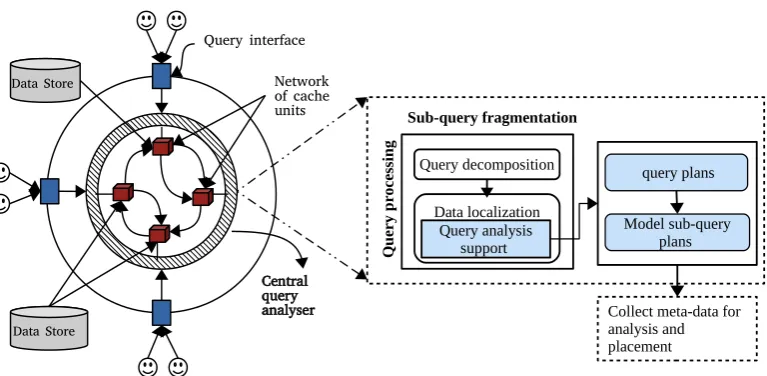
This section details the key architectural features for query analysis of CommCache with the help of examples. In its current version, CommCache is implemented with a global centralised environment for query processing. We consider a network of dis-tributed caches connected to the central query processing unit. As shown in Figure 1, user queries are submitted to the central query analyser. The query processor receives user queries and makes query execution plans.
The working of CommCache is divided into two phases; (i) theactive cache phase
during which, the cache management collects queries and query patterns are analysed and (ii) the cache maintenance phase, the cache replacement policies are chosen to maintain the cache coherence and re-usability of cached content. Both these phases complement each other to decidewhatto cache,how longto cache andwhereto cache the data. The query analyser collates query plans, fragments them into sub-queries and assumes the responsibility for searching and retrieval of all fragments available for a query during the active cache phase. During the maintenance phase, it examines semantic regions of interest and relocates sub-queries according to demographic infor-mation, if necessary. Thus, SQF tracks changing workloads and readjusts the cache contents.
Data Store
Data Store
Network of cache units
Central query analyser Query interface
query plans Query decomposition
Q
u
er
y
p
ro
ce
ss
in
g
Model sub-query plans Data localization
Query analysis support Sub-query fragmentation
Collect meta-data for analysis and placement
Figure 1: Sub-query fragmentation unit in the CommCache environment
Scenario 1. There are two non-replicated databases (DB1 and DB2) at two loca-tions (separated geographically), Location1 & Location2 respectively. Tables em-ployee(empId, name, age),project(projId, projName, empId)are part ofDB1and table
estimation(projId, projLoc, cost)is a part of DB2. The database instance is shown in the Figure 2. These databases do not need be homogeneous databases. We assume translation of data across heterogeneous databases to be an implicit step during the query planning. Consider queries, query1, query2 and query3 that request data from these databases.
DB1
employee project
empId age
name
assigned
N M
projId projName
empId
DB2
estimation
projId
projLocestimation
Location1 Location2
Figure 2: Two databases and their contents used in Scenario 1
Query 1 This query is to find names of employees, their projects and the project loca-tions, where project cost is under 50,000.
SELECT empName, projName, projLoc
FROM employee(DB1), project(DB1), estimation(DB2)
WHERE ((employee.empId=project.empId) AND
Query 2 This query obtains the names of projects that cost under 50,000 where em-ployees older than 45 years of age are working.
SELECT projName
FROM employee(DB1), project(DB1), estimation(DB2)
WHERE ((employee.age > 45)AND((employee.empId = project.empId)
AND (estimation.cost < 50000)))
Query 3 This query is to find all employee names who are older than 45 years.
SELECT empName
FROM employee(DB1)
WHERE (employee.age > 45)
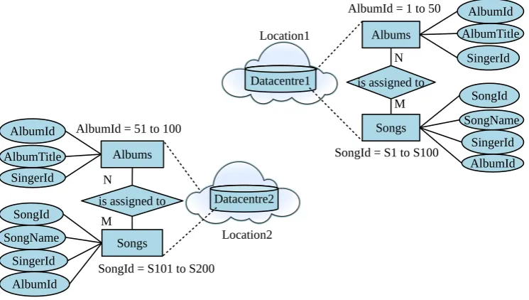
Scenario 2. Two horizontally fragmented distributed data centres contain
horizon-Datacentre1
Albums
Songs
AlbumId
SingerId AlbumTitle
is assigned to N
M SongId SongName
SingerId
Datacentre2 Albums
Songs AlbumId
SingerId AlbumTitle
is assigned to N
M SongId
SongName SingerId
AlbumId = 51 to 100
AlbumId = 1 to 50
SongId = S101 to S200
SongId = S1 to S100
AlbumId
AlbumId
Location1
Location2
Figure 3: Model of horizontally fragmented distributed data centres in Scenario 2.
tally fragmented data of two tablesAlbums(AlbumId, AlbumTitle, SingerId)andSongs (SongId, SongName, SingerId) at two geographically separated locations. The table ’Albums’ is horizontally fragmented on the primary key ’AlbumId’. Similarly, the table’Songs’is horizontally fragmented on the primary key’SongId’.
All tuples in Albums table ranging from 1 to 50 are stored at Location1 in Data-store1and tuples from 51 to 100 are stored atLocation2inDatastore2. All tuples in theSongstable ranging from S1 to S100 are stored atLocation1inDatastore1and the tuples from S101 to S200 are stored atLocation2inDatastore2. Database instance is as shown in Figure 3. Consider the following queries sent to these data centres1.
Query 4 This query obtains all song names stored in the table Songsfrom all frag-ments of the table.
SELECT SongName FROM Songs;
1This scenario is a reproduced version of the example given at
Query 5 This query is to get titles of albums and names of songs sung by singers present in albums.
SELECT al.AlbumTitle, so.SongName
FROM Albums AS al, Songs AS so
WHERE al.SingerId=so.SingerId AND al.AlbumId = so.AlbumId
4
Sub-Query Fragmentation
The previous section introduced the environment within which dispersed groups of users query distributed databases. This section introduces the theoretical model of sub-query fragmentation that enables the distributed caching system that serves those groups of users.
4.1
The Sub-query Concept
We can formally define a sub-query as
Definition 1 A queryqi is a sub-query of a queryQifqi is a valid query that can be
executed independently and its result can be combined with that of other sub-queries ofQto produce the result ofQ.
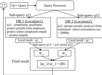
A sub-query can be further fragmented into one or more sub-query plans depending on the need and possibility to fragment further. Since sub-queries are the parts of query execution plans, an atomic sub-query is defined as an indivisible sub-query or the aggregation of sub-queries that are often queried together. One of the possible query plans for this query is given in the Figure 4. In this plan, all the data needed from DB1 is retrieved through a single access. For the purpose of illustration of distributed processing of the query, this plan ignore any local execution plans within a database to compute local results.
Example 1 Consider the Query 1 from Scenario 1.
• sub-query q11:
SELECT employee.empId, project.projName, project.projId FROM employee, project
WHERE employee.empId = project.empId⇒(partial) local result(qr11)
• sub-query q12:
SELECT (estimation.projId, estimation.projLoc) FROM estimation
WHERE (estimation.cost < 50000)⇒(partial) local result(qr12)
• sub-query q13:
SELECT (empName,projName, projLoc) FROM qr11, qr12
Query Processor Q1= Query
q11: (empName, projName, project.projId) from employee, project where (employee.empid = project.empid)
q12: (project.projId, projLoc) from estimation where (estimation.cost < 50000)
Local result - qr 11
qr11 qr12
(qr11 U qr12 ) = QR1 DB 1 (Location1)
Sub-query q13 = q11 (join) q12
Sub-query q11
Local result - qr 12
Sub-query q12
Final result
DB 2 (Location2)
Figure 4: Sample query plan for Query 1
The sub-queryq11has a join operation between tablesemployee&project. Sub-query
q12 is an atomic sub-query, as the result data fragment is produced as a single unit.
Sub-query q13 is a distributed join (or aggregation shown as S
in Figure 4) of the result of two sub-queries q11 and q12. Since sub-queries are executed independently,
each sub-query can be considered as a query on its own.
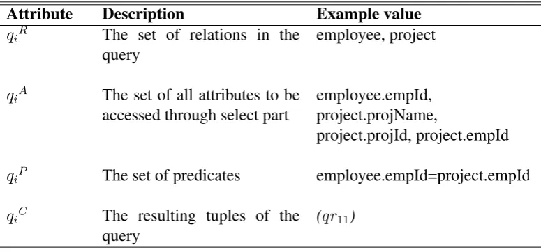
In general, a sub-query qi can be described by a tuple qi=hqiR, qiA, qiP, qiCi as
defined in [4] and is explained in Table 1. Since atomic sub-queries are similar to semantic segments, we can derive that a sub-querys can be answered bytgiven that (sC ∧tC) = sC. In other words,sC ⊂ tC. Similarly, other comparisons such assC is
equivalenttotC, to determine whetherscan be answered bytfollow the definitions of [4] while searching the cache for contained query.
4.2
Notational Representation of a Query
A QueryQis an aggregation of its sub-queries executed in a combination of parallel and sequential execution as defined by the query plan. We introduce an execution operator ‘k’ for sub-queries that can be executed concurrently. Similarly, ‘ ’ represents a sequential operator for sub-queries that must be executed in a predefined sequence. Thus, a query plan can be written using the infix notation2 of sequential and parallel
2Infix notation is a simple to read notational representation for writing algebraic and logical
Attribute Description Example value qiR The set of relations in the
query
employee, project
qiA The set of all attributes to be
accessed through select part
employee.empId, project.projName,
project.projId, project.empId
qiP The set of predicates employee.empId=project.empId
qiC The resulting tuples of the
query
(qr11)
Table 1: Tuple attributes of a sub-query for the sub-queryq11.
execution operators written in-between their sub-queries. It follows that,
(q∪q∪..∪qn) = n
[
k=1
qk =Q (1)
where,∪denotes a parallel or sequential execution operator for aggregation.
A simplified sequence of operations for sub-query execution to get the query result is shown in Figure 5a forQ. Let the intermediate result generated by the sub-query plan q11 be qr11 and that of sub-query plan q12 be qr12. The overall result is
aggre-gated asQR1on join(qr11.projId =qr12.projId). Sub-query plansq11andq12can be
executed as two independent plans in parallel. The aggregation forq13depends on the
results ofq11andq12. It means, execution ofq13cannot be performed until the
execu-tion of bothq11andq12are completed. Henceq13is executed sequentially afterq11and
q12. Using the notation,Q1is:
(((q11)k(q12)) (q13))⇒Q1 (2)
4.3
The Query Evaluation Tree
A query evaluation tree (QET) for a queryQis the graphical representation of a query in the infix order of execution. It is similar to the query execution tree presented in [19]. In a QET, sub-queries are found at leaf nodes. Each intermediate node is an execution operation performed on child nodes. When there is more than one child plan to a parent node, it is assumed that child plans are to be executed in the order of left node to right node. When a sub-query needs to be fragmented further, the evaluation tree replaces an execution operator, and further fragmented sub-queries are added as child nodes.
Start
q11 q12
Final result- QR1
sub-query
qr12 qr11
q13
sub-query
(a) Query plan with sub-queries
||
q12 (q11 || q12)
Parallel execution (q
11 || q12)_(q13)
Sequential execution
((q11 || q12)_ q13) => Q1
(q13)
q11
q13 _
(b) Tree with execution operators
Figure 5: Query Evaluation Tree (QET) for the queryQ1
the sub-query’s result. A leaf node consists of metadata of the sub-query result. The query evaluation tree for the queryQ1with execution operators is shown in Figure 5b. The structure of the node is given in Table 2.
Attribute Value
Sub-query (qi) infix expression (Notational representation ofqi)
Semantics (qi) hqiR, qiA, qiP, qiCi(Description of semantic segment)
Address a pointer to the physical address ofqi
Table 2: The structure of a node in the query evaluation tree
4.4
Query Complexity
The Complexity of a query is the number of sub-queries to be executed in a query plan. In other words, complexity is the number of leaf nodes of the query evaluation tree. The complexity of a query is used to understand the processing requirements for a given query. A higher number of sub-queries in a query indicates higher processing overheads. Query complexity influences outcome of the analysis of query patterns. It is used in the decision making whether it is optimal to fragment a query further during the maintenance phase.
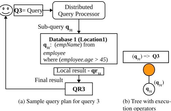
SELECT (empName)
FROM employee(Database1)
WHERE (employee.age > 45)
Distributed Query Processor
Q3= Query
q31: (empName) from
employee
where (employee.age > 45)
Local result - qr31
QR3
Database 1 (Location1)
Sub-query q31
Final result
(a) Sample query plan for query 3
q31
(q31) (q31) => Q3
(b) Tree with execu-tion operators
Figure 6: Query Evaluation Tree (QET) for the queryQ3
For this query, a possible query plan is shown in Figure 6a with a single sub-query. The equivalent query evaluation tree is shown on Figure 6b.
• sub-query q31: SELECT empName FROM employee(DB1) WHERE (employee.age>45)
Example. Consider query 4 from Scenario 2.
SELECT SongName FROM Songs;
For this query, a possible query plan is shown in Figure 7a with following sub-queries:
• sub-query q41: SELECT SongName FROM Songs (Location 1)
(This sub-query retrieves allSongNamesfromSongId=1to
SongId=100from the horizontal fragment at Location 1)
• sub-query q42: SELECT SongName FROM Songs (Location 2) (This sub-query retrieves allnames of songsfromSongId=101to
SongId=200from the Horizontal fragment at Location 2)
• final result: Aggregation of results of sub-query q41 and sub-query q42
Distributed Query Processor
Q4= Query
q
41: ( SongName) from Songs
q
42 :( SongName) from Songs Local result - qr41
Aggregation (qr41 Uqr42)= QR4
Data centre2
Data centre1
Local result - qr42
Final result
Distributed Query Decomposition(DQD)
Sub-query q41 Sub-query q
42
(a) Sample query plan for query 4
||
q41 q42
(q 41 || q42)
Parallel execution
(q41 Uq42) =>Q4
(b) Tree with execution opera-tors
Figure 7: Query Evaluation Tree (QET) for the queryQ4
balancing across servers, it is logical to consider them as two separate data centres). The third operation is only the aggregation of two query results. Since it is a simple union operation performed on two sub-query resultsets we do not consider as a separate sub-query. This query has two sub-queries. Hence the complexity of the query 4 is 2. Similarly, the query 1 (in Figure 5b) has three leaf nodes. So its complexity is 3.
4.5
The Cached Query Model
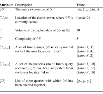
When a frequent sub-query is cached, it becomes an independentcached query object. We use a ‘♦’ notation to distinguish a cached query ‘♦S’ from a user queryS.
A cached query is made up of two parts. One, that defines the sub-query plan and second, a pointer to the physical address where the result is cached. The object profile of a cached query consists of the usage information of the query during its ‘cache life time3’. These attributes provide adequate information for the analysis and prediction
of future needs of users during cache maintenance.
A Cached Query♦S is a sub-query result and along with its meta-data parame-ters. A cached query is represented as a tuple
h♦S, CLoc, V, C,{TuLoc},{FuLoc},{Di}i.
Example. A cached query♦S=
h((qa kqm) qn), (cache-2), 10, 3,{3,4,2},{10,12,10},{qa, qb, qk}i.
The description of these parameters is explained in Table 3.
Attribute Description Value
♦S The query expression ofS ((qa kqm) (qn))
CLoc Location of the cache server, where♦Sis currently cached
(cache-2)
V Volume of the cached data of♦Sin GB 10
C Complexity of♦S 3
{TuLoc} A set of time stamps,♦Srecently used at
each of the user locations ’uLoc’
{(uloc-1),3},
{(uloc-2),4},
{(uloc-3),2}
{FuLoc} A set of frequencies (no.of times query
accessed) ♦S has been requested from each user location ’uLoc’
{(uloc-1),10},
{(uloc-2),12},
{(uloc-3),10}
{D} List of other queries with which ♦S has been queried together
{qa, qb, qk}
Table 3: Description of a Cached Query♦S
4.6
Cache Granularity
Thecache granularity is the smallest independent cacheable object. For an attribute or tuple caching policy, the granule is an attribute or a tuple respectively. Commonly, data transfers are measured as the number of memory pages [27]. The physical size of a cache granule is a page. Though query objects are cached at the page level, from the logical point of view, a sub-query (result) is the granule with sub-query fragmentation. A SQF cache granule can have a variable size due to the frequency of a sub-query requested along with other sub-queries.
4.7
Query Equivalence and Overlap
The query equivalence is essential when checking whether a user query can be an-swered by the cache. Equivalence checks whether the result needed by a user query is equivalent to, or part of, any of the cached queries.
4.7.1 Equivalent Queries
Definition. Alternately, two queries (S,♦T) areequivalentS ≡♦T, when their final results yield the same resultset with different sub-queries.
Since the root node of a query evaluation tree is an aggregation of the complete query, equivalence for two queries can be checked by the query expression or answer-able by the semantic definition [4] (explained in the Tanswer-able 2) at its root node.
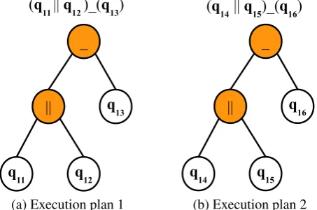
Example. Distributed query plan generation depends on many factors such as load distribution, process distribution, and location dependence of data availability [28]. A query may have more than one execution plan leading to many possible strategies. For example, another query execution plan for Query 1 (from Scenario 1) can be with following sub-queries:
• sub-query q14: SELECT empId,empName FROM employee⇒partial result (qr14).
• sub-query q15:
SELECT project.projName, project.empId, estimation.projLoc FROM project, estimation
WHERE (project.projId=estimation.projId) AND (estimation.cost < 50000)⇒partial result (qr15).
• sub-query q16: SELECT empName, projName, projLoc FROM qr14, qr15
WHERE ( qr14.empId = qr15.empId )⇒complete result (QR1).
The complete query plan with the above sub-queries is
(((q14)k(q15)) (q16))⇒Q1 (3)
_
|| q13
q
11 q12
(q11 || q12 )_(q13)
(a) Execution plan 1
_
|| q16
q14 q15
(q14 || q15)_(q16)
(b) Execution plan 2
Figure 8: Equivalent query evaluation trees forQwith different sub-queries
Two query evaluation trees for Q with sub-queries q11, q12, q13 and q14, q15, q16
Algorithm 1EquivalentQuery (S,T)
1: Input:QueryS, QueryT 2: Output:boolean (true or false)
3: root-S⇐root of QET forS .root node of the cached query
4: root-T⇐root of QET forT .root node of the query to search 5: if(root-S.sub-queryequalsroot-T.sub-query) then
6: returntrue 7: elsereturnfalse 8: end if
4.7.2 Query Overlap
Definition. QuerySiscompletely overlappedby a query♦T, i.e., (S ⊆♦T), when theroot nodeof querySisequivalenttoone of the nodesof the (query♦T). It follows that, (S∩♦T) = S.
Example. Consider Query 2 and Query 3 from Scenario 1:
Query 2 obtains the names of projects (with cost<50000) where employees above the age of 45 years are working.
SELECT (projName)
FROM employee(DB1), project(DB1), estimation(DB2)
WHERE ((employee.age>45) AND ((employee.empId=project.empId) AND (estimation.cost < 50000)));
Query 3 is to find all employee names whose are above 45 years of age.
SELECT (empName)
FROM employee(DB1)
WHERE (employee.age > 45)
In the above queries, Query 3 is completely overlapped by Query 2.
Definition.QuerySand query♦T arepartially overlapped, whenone or more nodes
of the evaluation tree ofSareequivalenttoone or more nodes of the evaluation tree of query♦T. It follows that,S∩♦T 6=null.
Example. Consider sub-queries ofQandQof Scenario 1.
• sub-query q11:
SELECT employee.empId, project.projName, project.projId FROM employee, project
WHERE employee.empId=project.empId
• sub-query q12: SELECT estimation.projId, estimation.projLoc FROM estimation
WHERE estimation.cost < 50000
FROM qr11, qr12
WHERE (qr11.projId=qr12.projId )⇒complete result(QR1)
Following are one of the possible query execution plans for Query 2:
• sub-query q21: SELECT project.projName, project.projId FROM employee, project
WHERE (employee.empId=project.empId) AND (employee.age>45)
• sub-query q22: SELECT estimation.projId FROM estimation
WHERE (estimation.cost < 50000)
• sub-query q23: SELECT projName FROM qr21, qr22
WHERE (qr21.projId = qr12.projId) ⇒ complete result(QR2)
From the above queries, thesub-queryq22can be answered bysub-queryq12. If the
results of queryQ1 were cached, then the queryQ2 can be partially answered by the queryQ1. The remaining part of the queryQ2,sub-queryq21cannot be answered by
the queryQ1.
4.8
Searching for Contained Query
The process of searching whether a query contains the result is done by checking the equivalence. Since we consider only sub-queries, we introduce a logical layer (such as an index) between the query interface and the physical storage location. The index consists of evaluation trees ordered by the demand for a sub-query. A user query should be searched against each of the root nodes of the cached queries to find what part of the user query can be answered by each of the cached queries.
When a cached query (♦T) contains the user query (S),i.e., Sis partially or fully overlapped by♦T, it is enough to search the query evaluation tree of♦T according to breadth-first order since sub-queries are stored in a top-down manner to get the biggest part that can be answered by ♦T. We say, set of all sub-queries of S that can be answered by♦T is the ContainedQuery (HS), and set of all sub-queries that cannot be answered is the RemainderQuery (OS). Algorithm to search for a completely overlapped is present in Algorithm 2. Algorithm 3 explains to search cache for a user querySin general.
ContainedQuery(HS) = {si |si ⊆♦T} (4)
RemainderQuery(OS) ={si |si ∈(S−HS)} (5)
From these definitions, we can derive how a query can be answered by the cache:
• A query S can be completely answered by the ♦T in cache if, S ≡ ♦T or
• A queryScan also becompletely answeredby the cache, if all nodes inScan be completely answered by one or more queries in the cache (S = HS) and (OS=∅(null)).
• A query S can be partially answered by the cache, if the RemainderQuery (OS6=∅(null)).
• A queryS isnot foundin the cache if, (S=OS).
Algorithm 2isContained (S⊆♦T)
1: Input: S
2: Output: Internal node (ti) 3: ifEquivalentQuery(S,T)then
4: returnroot-T .equivalent trees
5: elsedo Breadth-First-Traversal (root-T)
6: ifroot-Sequalsinternal-node (ti)then 7: returnti
8: elsereturnnull
9: end if
10: end if
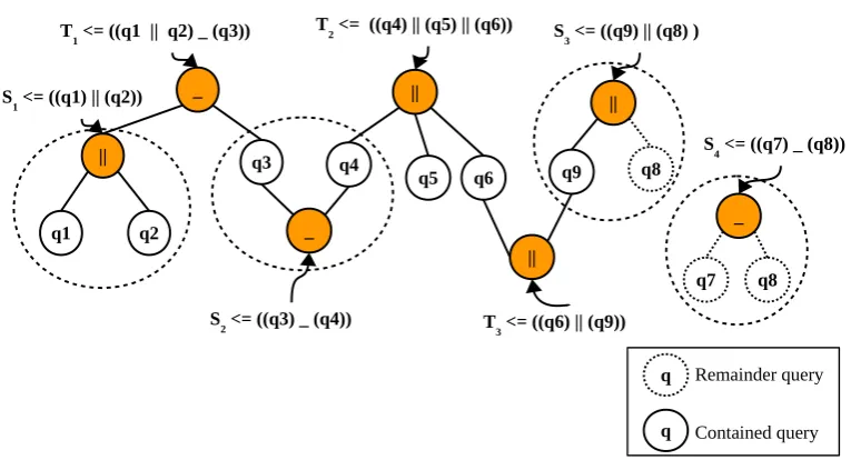
Example. Suppose we have a cache with 3 queries stored. A logical view of the cache is shown in Figure 9. Consider a set of queries cached and set of user queries given below.
Cached queries User queries
♦T1 ⇐((q1kq2) (q3)) S1 ⇐(q1||q2 )
♦T2 ⇐((q4)k(q5)k(q6)) S2 ⇐((q3) (q4))
♦T3 ⇐((q6)k(q9)) S3 ⇐((q9)||(q8))
S4 ⇐((q7) (q8))
The logical view of contained and remainder queries for these user queries are shown in Figure 10. In this example,S1 can be fully answered by the cache as S1 ≡
♦T1. Similarly, S2 can also be fully answered by the cache as the leaf nodes (q3) and
(q4) ofS2are partially contained in♦T1 and♦T2. However,S3 can be only partially
answered by the cache. It has a remainder query OS3 = (q8). The contained query
HS3= q9. S4 cannot be answered at all by the cache as (q7) and (q8) are not stored in
cache. Hence,HS4 =∅andOS4 =S4.
5
Evaluation
_
|| q3
q1 q2
||
q6 q4 q5
T1 <= ((q1 || q2) _ (q3)) T2 <= ((q4) || (q5) || (q6))
|| q9
T3 <= ((q6) || (q9))
Figure 9: Sample queries present in cache
_
|| q3
q1 q2
||
q6 q4
q5 T1 <= ((q1 || q2) _ (q3))
_
q7 q8
_
T2 <= ((q4) || (q5) || (q6))
S4 <= ((q7) _ (q8))
|| q9
T3 <= ((q6) || (q9)) S1 <= ((q1) || (q2))
S2 <= ((q3) _ (q4))
S3 <= ((q9) || (q8) )
||
q8
q Remainder query
q Contained query
Algorithm 3SearchCache(S)
1: Input: QueryS
2: Output: ContainedQuery (HS), RemainderQuery (OS) , status
3: HS =∅
4: OS ={si |si ∈S} 5: for each cache unitdo
6: for each cached query♦T do
(HS,OS) = QUERYSEARCH(HS,OS,♦T ) 7: if(OS =∅)then
8: return (HS,∅,fully found)
9: end if
10: end for
11: end for
12: if(OS=S)then
13: return (∅,OS,Not found)
14: elsereturn (HS,OS,partially found)
15: end if
16:
17: %Function to search for a queryS within a cached query♦T
18: functionQUERYSEARCH(HS,OS,♦T )
19: Output: ContainedQuery (HS), RemainderQuery(OS)
20: foreachsi ∈OSdo
21: if(si≡♦T) OR (si ⊆♦T)then 22: HS →HS∪si
23: elseOS →OS∪si
24: end if
25: end for
26: return (HS,OS)
Query Workloads
The query workloads are a continuous stream of queries submitted. Queries access data from multiple databases.
sub-query fragmentation needs constantly changing workloads with partial over-laps. We have developed a synthetic query generatorQgene- to generate workloads as query plans with the details of user location(s), cache location and the timestamp.4.
Qgene allows users to set configuration settings for (i) the duration of the observation time window, (ii) number of queries in the workload per window, (iii) varous statisti-cal distributions for sub-query overlap and inter-query arrival time. Qgene also allows vary query complexity (number of sub-queries). A random factor is introduced to the workloads to eliminate any bias. Each of the following experiments was executed multiple times and obtained an average value.
Experimental Settings
All experiments for the evaluation are conducted on Java based simulator (JDK 1.8). All experiments were conducted for Poisson, Uniform and Exponential distributions of workloads for query overlap and sub-query repetition.
Other variable settings relate to the cache environment. The maximum number of cache agents is decided based on the inter-cache communications that can be handled by the hardware configuration in the laboratory. We set the number of cache units in the network to be 20. In the distributed environment, the ideal data placement algorithm to place data near users influence the response time. We set the data placement to follow Greedy placement policy for a uniform evaluation of the caching techniques.
To understand the impact of cached segments as distributed independent objects and the need for SQF, the caching techniques are evaluated and compared for three metrics; (i) average response time, (ii) cache utilisation and (iii) cache stability. The response time depends on several factors such as (a) caching policies used, (b) cache replacement heuristics, and the (c) distributed data placement methods etc.. Hence, in a fundamental scenario without data placement, SQF and Semantic caching are expected to perform almost the same. Cache utilisation and cache stability metrics actually highlight the advantage of SQF. Each of these metrics are observed for 14 continuous time epochs. Observations for every epoch were repeated for 8 to 12 times. The average is plotted with standard errors.
5.1
Average Response Time
The response time is measured as the time elapsed from a query sent from the user to the time the reply is received. It is a relevant metric as the objective for any caching technique is to minimise the response time. For continuous query workloads, we con-sider the average response time per workload. In the simulation environment, the response time is measured as logical clock ticks. The symbol notation to calculate average response time lapsed is presented in the Table 4.
4A detailed description of design and query modeling parameters will be provided for evaluation and
Notation Description
N total number of queries
lt average cache latency
DQ processing time for a queryQat data servers
Qproc average processing time for a queryQ
tqi data transfer time on network forqifrom cache
VQnotf ound volume of data not found in cache
Table 4: Notation Table
Average response time= 1
N(lt+DQ+tQ+Qproc+tqi) (6)
Where,
lt= query lookup time + actual data retrieval time
DQ =VQnotf ound*Dt
tQ= time to transferVQnotf ound*dnet
tqi = Inter cache transfer time * number of hops
0 100 200 300 400 500
1 2 3 4 5 6 7 8 9 10 11 12 13 14
Epoch
Response time *1000 ticks
caching_technique
Full_query Semantic_caching SQF
(a) Poisson query input
0 100 200 300 400 500
1 2 3 4 5 6 7 8 9 10 11 12 13 14
Epoch
Response time *1000 ticks
caching_technique
Full_query Semantic_caching SQF
(b) Exponential query input
0 100 200 300 400 500
1 2 3 4 5 6 7 8 9 10 11 12 13 14
Epoch
Response time *1000 ticks
caching_technique
Full_query Semantic_caching SQF
(c) Uniform query input
Discussion:
The response time is observed for continuous epochs is plotted in Figures 11a, 11b, and 11c. The full-query resultset caching model stores results as a single unit at one location. Hence it resulted in a high number of cache faults and high response time. In general, this policy observes high response time for all types of query distributions. SQF and SC models performed almost similarly for Exponential and Poisson distribu-tions. Under similar conditions SQF follows semantic rules for the fragmentation of queries. The semantic model showed up to 10% lower response times than SQF for Uniform distribution. One reason for SQF to have high response time could be that SQF further fragments queries according to user requirements and association with other queries in caches. Since sub-queries are repeated uniformly, the overall response time is slightly higher for SQF.
5.2
Adaptivity to Changing Workloads
The plot in the Figure 12 shows the adaptivity of caching techniques to changing query inputs over a continuous period. The input query distribution patterns are changed after every five epochs. The experimental settings are similar to the above experiment. Query workloads are mixed distribution of sub-query repetition.
0 100 200 300 400 500
1 2 3 4 5 6 7 8 9 10 11 12 13 14 Epoch
Response time *1000 ticks
Caching_technique
Full_query Semantic_caching SQF
Figure 12: Adaptivity to changing workloads
Discussion:
5.3
Cache Utilisation - Data Found Vs Caching Policies
The percentage of data found in the cache influences the response time. Higher vol-umes of data found in the cache (VQf ound) reflect the ability of cache selection to max-imise the cache utilisation. In this experiment, we allowed cache models to learn from query patterns. The learning is done by finding out the finest grain of query fragments that are repeated more than a threshold. The learning gets the support from the associ-ated sub-queries with each of the frequented sub-query. The percentage of data found in cache is compared across three caching policies.
0 10 20
1 2 3 4 5 6 7 8 9 10 11 12 13 14 Epoch
P
ercentage Data f
ound
caching_technique
Full−query Semantic−caching SQF
Figure 13: Comparison percentage data found in cache across caching techniques
Discussion:
It is observed from the Figure 13 that the semantic model performed better than other approaches during the initial epochs. Although initial performance of SQF in terms of percentage of data found in cache was lower than this of SC, SQF observed the finer grains of query fragment repetition and cached the query fragments effectively. The observation capability provided SQF to “learn” user requirements up to the finest grain and performed better over the subsequent epochs. Nearly 12.5% more data is found than in the case of semantic caching model. The results in Figure 13 are presented for Uniform distribution.
5.4
Cache Stability - Inter-Cache Data Transfers
Number of sub-query objects to relocate =δn
Average volume of a sub-query (qi) in GB =vqi
Average data transfer cost for inter-cache transfers per GB=dnet
Average cost Inter-cache data transfers= 1 δn
δn X
i=1
(δn∗vqi∗dnet) (7)
The parameter (δn) varies with the efficiency of the data placement algorithm to place
a data segment. The parameter (vqi) varies with changing workloads. Queries with
higher complexity lead to higher number of data accesses and hence transfers. The fol-lowing experiment compares the response time for inter-cache data transfers to reach to the cache set nearer to the user. The comparison is made using three cache tech-niques. (i) caching with sub-query fragmentation (SQF), (ii) semantically distributed data and (iii) caching full-query resultsets.
25 50 75 100
1 2 3 4 5 6 7 8 9 10 11 12 13 14 Epoch
Response time *1000 ticks
caching_technique
Full_query Semantic_Caching SQF
Figure 14: Response time due to inter-cache data transfers
Discussion:
The results in Figure 14 presented represent Uniform distribution of sub-queries. It is observed that the sub-query fragmentation (SQF) showed a clear advantage over other caching techniques used in distributed environment. SQF has fewer inter-cache transfers as this approach stores all related data segments together.
5.5
Overhead of Sub-query Fragmentation
once. So, SQF clearly tends to store more data initially. However, in the distributed environment, if the data is frequently needed at two locations at all times, then it makes sense to create copies of data and distribute them over different locations. This will have a significant reduction in the query response time. Sincea is joined withb, the sub-query will be treated as an independent unit from acin SQF. Here we could not present all our findings and methods to identify the association between frequently queried data segments due to lack of space.
6
Conclusion & Future Work
The work presented in this paper is a part of the research project - CommCache, a com-munity shared cache framework for the optimization of data transfers. In this paper, we have discussed the problem of identifying suitable data fragments to cache in the distributed environment. The proposed sub-query fragmentation technique fragments user queries into sub-queries based on the repetition of partial query segments (sub-queries). They are stored together to provide quick retrieval of data. Though SQF is an extension to the semantic caching, sub-queries are modeled as portable objects suitable to the distributed environment.
Overall, the SQF approach performed better than other caching approaches in the distributed environment. For the average response time, SQF is very effective in dy-namic environments where workloads are changing as it is able to adapt to those changes quicker and better than existing approaches. Using traditional workloads, SQF outperformed other methods in most of the instances. It is only second best, after SC for static workloads. Since SQF can be used find patterns of data accesses, it is possible to cache more accurate data than other techniques. Over a period of time, the percentage of data found is higher than other methods.
At present, SQF is restricted to the following limitations. The approach is mainly focused on distributed caches to understand the patterns of user queries using dis-tributed learning. Hence a centralised global query processor is assumed to manage the distribution of query segments. In future, we would like to extend the use of SQF for de-centralised environments. Another limitation is, the SQF approach depends on query execution plans. This means, a different execution plan might lead to repro-cessing of the entire query. However, the query planner can consult existing cached contents before creating a plan.
References
[1] Santhilata Kuppili Venkata, Jeroen Keppens, and Katarzyna Musial. Adaptive Caching Using Sub-query Fragmentation for Reduction in Data Transfers from Distributed Databases. In N. P. F. Lorente and K. Shortridge, editors, ADASS XXV, ASP Conf, Ser. ASP, 2016.
[2] Shaul Dar, Michael J. Franklin, Bj¨orn T. J´onsson, Divesh Srivastava, and Michael Tan. Semantic Data Caching and Replacement. InProceedings of the 22th Inter-national Conference on Very Large Data Bases, VLDB ’96, pages 330–341, San Francisco, CA, USA, 1996. Morgan Kaufmann Publishers Inc.
[3] Arthur M. Keller and Julie Basu. A Predicate-based Caching Scheme for Client-server Database Architectures. The VLDB Journal, 5(1):035–047, January 1996.
[4] Qun Ren, Margaret H. Dunham, and Vijay Kumar. Semantic Caching and Query Processing. IEEE Trans. Knowl. Data Eng., 15(1):192–210, 2003.
[5] Blesson Varghese, Nan Wang, Dimitrios S. Nikolopoulos, and Rajkumar Buyya. Feasibility of Fog Computing. CoRR, abs/1701.05451, 2017.
[6] Ivans Stojmenovic. Fog computing: A cloud to the ground support for smart things and machine-to-machine networks. In2014 Australasian Telecommunica-tion Networks and ApplicaTelecommunica-tions Conference (ATNAC), pages 117–122, Nov 2014.
[7] Mamta Agiwal, Abhishek Roy, and Navrati Saxena. Next Generation 5G Wire-less Networks: A Comprehensive Survey. IEEE Communications Surveys Tuto-rials, 18(3):1617–1655, thirdquarter 2016.
[8] David J. DeWitt, Philippe Futtersack, David Maier, and Fernando Velez. A Study of Three Alternative Workstation Server Architectures for Object-oriented Database Systems. In Proceedings of the 16th Intl Conf on VLDB, pages 107– 121. Morgan Kaufmann Publishers Inc., 1990.
[9] Hector Garcia-Molina, Jeffrey D. Ullman, and Jennifer Widom. Database Sys-tems The Complete Book, 2 ed. Pearson Prentice Hall, 2009.
[10] Stratos Papadomanolakis and Anastassia Ailamaki. AutoPart: Automating Schema Design for Large Scientific Databases Using Data Partitioning. In SS-DBM, pages 383–392. IEEE Computer Society, 2004.
[11] ChungMin Melvin Chen and Nicholas Roussopoulos. The implementation and performance evaluation of the ADMS query optimizer: Integrating query result caching and matching. In Matthias Jarke, Janis Bubenko, and Keith Jeffery, ed-itors, Advances in Database Technology — EDBT ’94, pages 323–336, Berlin, Heidelberg, 1994. Springer Berlin Heidelberg.
[13] Norvald H. Ryeng, Jon Olav Hauglid, and Kjetil Nørv˚ag. Site-autonomous dis-tributed semantic caching. In William C. Chu, W. Eric Wong, Mathew J. Palakal, and Chih-Cheng Hung, editors,SAC, pages 1015–1021. ACM, 2011.
[14] Upen S. Chakravarthy, John Grant, and Jack Minker. Logic-based Approach to Semantic Query Optimization. ACM Trans. Database Syst., 15(2):162–207, June 1990.
[15] Alfredo Go˜ni, Arantza Illarramendi, Eduardo Mena, and Jos´e Miguel Blanco. An Optimal Cache for a Federated Database System. Journal of Intelligent Informa-tion Systems, 9(2):125–155, 1997.
[16] Dongwon Lee and Wesley W. Chu. Towards Intelligent Semantic Caching for Web Sources. J. Intell. Inf. Syst., 17(1):23–45, 2001.
[17] Dongwon Lee and W. W. Chu. Semantic Caching via Query Matching for Web Sources. InProceedings of the Eighth International Conference on Information and Knowledge Management, CIKM ’99, pages 77–85, New York, NY, USA, 1999. ACM.
[18] Boris Chidlovskii and Uwe M. Borghoff. Semantic Caching of Web Queries.The VLDB Journal, 9(1):2–17, 2000.
[19] Jun Rao and Kenneth A. Ross. Reusing Invariants: A New Strategy for Correlated Queries. InProceedings of the 1998 ACM SIGMOD International Conference on Management of Data, SIGMOD ’98, pages 37–48, New York, NY, USA, 1998. ACM.
[20] Doaa Saad El Zanfaly, Reda A. Ammar, and Ahmed Sharaf Eldin. Modeling and analysis of a multilevel caching in distributed database systems. In Proceedings of the 9th ISCC 2006, Egypt, pages 140–145. IEEE Computer Society, 2004.
[21] Jason George McHugh. Data Management and query processing for semistruc-tured data. PhD thesis, Stanford University, 2000.
[22] Laura M. Haas, Donald Kossmann, and Ioana Ursu. Loading a Cache with Query Results. In Proceedings of the 25th International Conference on VLDB, VLDB ’99. Morgan Kaufmann Publishers Inc., 1999.
[23] Louis Degenaro, Arun Iyengar, Ilya Lipkind, and Isabelle Rouvellou. A Middle-ware System Which Intelligently Caches Query Results, pages 24–44. Springer Berlin Heidelberg, Berlin, Heidelberg, 2000.
[25] Beomseok Nam, Minho Shin, Henrique Andrade, and Alan Sussman. Multiple Query Scheduling for Distributed Semantic Caches. J. Parallel Distrib. Comput., 70(5):598–611, May 2010.
[26] Laurent d’Orazio, Fabrice Jouanot, Yves Denneulin, Cyril Labb´e, Claudia Ron-cancio, and Olivier Valentin. Distributed Semantic Caching in Grid Middleware. In Database and Expert Systems Applications, 18th International Conference, DEXA 2007, Regensburg, Germany, September 3-7, 2007, Proceedings, pages 162–171, 2007.
[27] Abraham Silberschatz, Peter Baer Galvin, and Greg Gagne. Operating System Concepts. Wiley Publishing, 8th edition, 2008.
[28] Tamer M. Ozsu and Patrick Valduriez. Principles of Distributed Database Sys-tems. Prentice Hall Press, Upper Saddle River, NJ, USA, 3rd edition, 2007.
[29] Rubao Lee, Minghong Zhou, and Huaming Liao. Request Window: An Ap-proach to Improve Throughput of RDBMS-based Data Integration System by Utilizing Data Sharing Across Concurrent Distributed Queries. InProceedings of the 33rd International Conference on Very Large Data Bases, VLDB ’07, pages 1219–1230. VLDB Endowment, 2007.