a
Operation in the turbulent jet field of a linear array of multiple rectangular
jets using a two-dimensional jet (Variation of mean velocity field)
Shigetaka Fujita1,a and Takashi Harima1
1
National Institute of Technology, Tokuyama College, Dept. of Mechanical and Electrical Engineering, Gakuendai, Shunan, Yamaguchi, 745-8585, Japan
Abstract. The mean flowfield of a linear array of multiple rectangular jets run through transversely with a two-dimensional jet, has been investigated, experimentally. The object of this experiment is to operate both the velocity scale and the length scale of the multiple rectangular jets using a two-dimensional jet. The reason of the adoption of this nozzle exit shape was caused by the reports of authors in which the cruciform nozzle promoted the inward secondary flows strongly on both the two jet axes. Aspect ratio of the rectangular nozzle used in this experiment was 12.5. Reynolds number based on the nozzle width d and the exit mean velocity Ue (≅ 39 m / s) was kept constant 25000. Longitudinal mean velocity was measured using an X-array Hot-Wire Probe (lh = 3.1 μm in diameter, dh = 0.6 mm effective length : dh / lh = 194) operated by the linearized constant temperature anemometers (DANTEC), and the spanwise and the lateral mean velocities were measured using a yaw meter. The signals from the anemometers were passed through the low-pass filters and sampled using A.D. converter. The processing of the signals was made by a personal computer. Acquisition time of the signals was usually 60 seconds. From this experiment, it was revealed that the magnitude of the inward secondary flows on both the y and z axes in the upstream region of the present jet was promoted by a two-dimensional jet which run through transversely perpendicular to the multiple rectangular jets, therefore the potential core length on the x axis of the present jet extended 2.3 times longer than that of the multiple rectangular jets, and the half-velocity width on the rectangular jet axis of the present jet was suppressed 41% shorter compared with that of the multiple rectangular jets.
1 Introduction
The object of this experiment is to operate both the velocity scale and the length scale of the multiple rectangular jets using a two-dimensional jet.
Many examples of multiple rectangular jets in industrial situations were found in the combustion equipment [1], the high lift devices [2] and the high thrust ejectors [3], they were applied to the rapid mixing and the operation of the mixing rate. If the two-dimensional nozzle shape was divided into multiple rectangular nozzles, the improvement of the mixing rate is expected because the various jets arrangement will be thought. However, the systematic conjecture is in very difficult situation for the reason of that there are so many parameters to be investigated, for example, nozzle aspect ratio, nozzle arrangement pitch, Reynolds number and turbulent intensity. Furthermore, many difficulties are existing in both the method and the cost of the nozzle manufacturing.
So far, Krothapalli et al., [4] (Nozzle length: L = 50 mm, Nozzle width: d = 3.0 mm, Nozzle aspect ratio: AR (L / d) = 16.67, Nozzle arrangement pitch: S = 8 d,
Channel type) and Marsters [5] (L = 38 mm, d = 3.96 mm, AR (L / d) = 9.6, S = 4.7 d, Channel type) reported about the multiple rectangular jets. The objective of both reports was to promote the thrust augmentation. In the report of the multiple rectangular jets by Krothapalli et al., [4], the streamwise variation of the characteristic scale in the CD (Characteristic Decay) region containing an initial region (20 times of nozzle width d) was almost the same with the result of the single rectangular jet by Krothapalli et al., [6] (L = 50 mm, d = 3.0 mm, AR (L / d) = 16.67, Channel type).
On the other hand, Yu [7] used the multiple rectangular jets of which those rectangular axes were arranged in a line (L = 2.0 mm, d = 1.0 mm, AR (L / d) = 2.0, S = 2.5 d) to make high quality gas wiping galvanized steel sheets with uniform thickness. In this case, an extent of the potential core length of the multiple rectangular jets is very important, but it is difficult to extent the potential core length effectively in the initial jet region. Therefore, a new method to improve the potential core length is expected. From these points of view, there are many subjects to be clarified, for example, the fundamental differences between the single C
rectangular jet and the multiple rectangular jets, and the developing and decreasing properties for the case of handling the multiple rectangular jets as the object of operation.
From the mentioned above, the present study adapted a new method of running through transversely with a two-dimensional jet to change the property of the multiple rectangular jets. This adaption was obtained from the reports by authors [8, 9, 10] of which the cruciform shape nozzle jet produced the inward secondary flow toward the jet centre region on both nozzle axes.
The object of the present study is to delay the decreasing rate of the velocity scale near the jet centre region and to repress the developing rate of the half velocity width of the multiple rectangular jets field using a two-dimensional jet which runs through transversely perpendicular to the multiple rectangular jets. In this report, this present multiple rectangular jets run through transversely using a two-dimensional jet will be called the present 3-D jet.
In the case of comparing the results of the velocity and the length scales between the present 3-D jet and the multiple rectangular jets, the results of multiple rectangular jets by authors will be used, instead of the results of multiple rectangular jets by Krothapalli et al., [4], because the multiple rectangular jets by authors have the same cross section shape at the nozzle exit section, rectangular nozzle width d (= 10 mm), aspect ratio (AR = 12.5) and arrangement pitch (S = 12.5 d) with the present 3-D jet.
Nomenclature
The nomenclatures used in this study are as follows: AR : Aspect ratio of the rectangular nozzle (L / d)
by : Half velocity width on the long axis (y axis) of the rectangular nozzle in the present 3-D jet and the multiple rectangular jets
D2 : Length scale which is equivalent to the two-dimensional jet nozzle width made from the total nozzle exit area of each three-dimensional jet d : Nozzle width (10 mm)
L : Length of long axis of the rectangular nozzle in the multiple rectangular jets (125 mm)
Lye : Half-length of long axis of each rectangular nozzle (L / 2 = 62.5 mm)
l : Length of long axis of the two-dimensional nozzle in the present jet (990 mm)
S : Arrangement pitch of the rectangular nozzle (125 mm)
U : Longitudinal mean velocity in the x-direction Ue : Longitudinal mean velocity at the nozzle centre
(x / d = 0, y / d = z / d = 0) of the exit plane (≅ 39 m / s)
Uox : Longitudinal mean velocity along the jet centreline (x axis: y / d = z / d = 0) on the x axis V : Lateral mean velocity in the y-direction W : Spanwise mean velocity in the z-direction x, y, z : Cartesian coordinate system with origin at the
rectangular nozzle centre of the exit plane in the present 3-D Jet (See figure1)
Subscript
e : Value at the nozzle exit centre of the present 3-D jet (x / d = 0, y / d = z / d = 0)
m : Value at the middle location (y / d = 0, z / d = 6.25) which is the centre between the rectangular nozzles of the present 3-D jet
ox : Value along the jet centreline (x axis) of the present 3-D jet
rms : Value of root mean square
2 Experimental equipment and
procedure
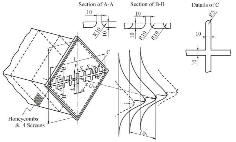
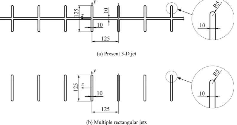
The configuration of the flowfield and the coordinate system are presented in figure 1. The jet flow facility consists of a turbo fan, a settling chamber with a 990 mm diagonal line, honeycomb and 4 mesh wire screens. The present 3-D jet nozzle which is made from the acrylic acid resin of 10 mm thickness, is installed at the end of the settling chamber. The main axis length L and the width d of the rectangular nozzle are made to be 125 mm and 10 mm respectively, because the magnitude of the inward secondary flow on the rectangular long axis showed the maximum value for the case of cruciform nozzle aspect ratio (L / d) = 12.5 [10]. The seven multiple rectangular nozzles are arranged with same pitch S = 125 mm (S / d = 12.5). Here, the configurations of both the present 3-D jet nozzle and the multiple rectangular jet nozzles are shown in figures 2-(a) and (b) for comparison. Longitudinal mean velocity were measured using an X-array Hot-Wire Probe (dh = 3.1 μm in diameter, lh = 0.6 mm effective length: lh / dh = 194) operated by the linearized constant temperature anemometers (DANTEC), and the spanwise and the lateral mean velocities were measured using a yaw meter. The signals from the anemometers were passed through the low-pass filters (10 kHz) and sampled using A.D. converter at 20 kHz. The processing of the signals was made by a personal computer. Acquisition time of the signals was usually 60 seconds (max acquisition time 100 seconds). The exit plane Reynolds number based on the nozzle width d and the exit mean velocity Ue, was kept constant 25000 throughout the present experiment. Furthermore, the value of the nozzle exit turbulent intensity urms / Ue was about 4×10⁻³. In this experiment, the uncertainty associated with the longitudinal mean velocity U is estimated at ±3% of Ue, which includes calibration error of the linearized constant temperature anemometers, and that of the spanwise mean velocity V and the lateral mean
velocity W is estimated at ±6% of Ue, which includes calibration error of the used yaw meter.
3 Experimental results and discussion
3.1 Streamwise variation of the longitudinal mean velocity
The streamwise variation of the longitudinal mean velocity profiles on both the y and z axes of the present 3-D jet (Black) are shown in figure 3, and the results of the multiple rectangular jets (Red) by authors are also shown for comparison in the region of 5 ≤x / d ≤50. The dotted line in figure 3 shows the z / d = 6.25 slice plane which is the middle location between the present 3-D multiple rectangular jets.
The profiles of the multiple rectangular jets on the y axis (Red) show the saddle-back shape which takes the minimum value at the jet centre and the maximum value near the jet end from the section of x / d = 5 to 30. On the other hand, the present 3-D jet (Black) shows a saddle-back shape of which the profile takes the maximum value at the jet centre and takes the local maximum value near the jet end, therefore, the saddle-back shape of the present 3-D jet is different from that of the multiple rectangular jets. Here, the reason of the value of U / Ue > 1.0 near the jet centre region within the region of x / d ≤20, comes both from the active inward advection transport of the mean kinetic energy (V ⋅ (U2 / 2) / y on the y axis, W ⋅ (U2 / 2) / z on the z axis) [11] and the nozzle cross section shape which produces the inward secondary flow (as will be shown in figure 4).
The profiles on the z axis for the multiple rectangular jets (Red) show a monotonous decrease from the maximum value at the jet centre region to the zero value at z / d = 6.25 within the region of x / d ≤15. In the region of x / d ≥20, the profiles decrease monotonically from the jet centre region to the minimum value at z / d =
(a) Present 3-D jet
(b) Multiple rectangular jets
6.25. On the other hand, the profiles on the z axis for the present 3-D jet (Black) at the sections of x / d = 5 and 10 take the maximum value at the jet centre region and decrease monotonically and then take the saddle-back shape. In the region of x / d ≥15, the profiles show the monotonic decrease from the maximum value at the jet centre (z / d = 0) to the minimum value at z / d = 6.25. The decreasing rate of the value near the jet centre region of the present 3-D jet (Black) is smaller than that of the multiple rectangular jets (Red).
From this result, it is confirmed that the decreasing rate of the streamwise velocity scale near the jet centre region is repressed compared with that of the multiple rectangular jets.
3.2 Comparison of the secondary flow velocity
In this section, the confirmation of the secondary flow production and the magnitude of the inward secondary flow on both the y and z axes will be examined. Figure 4 shows the comparison of the streamwise variation of the
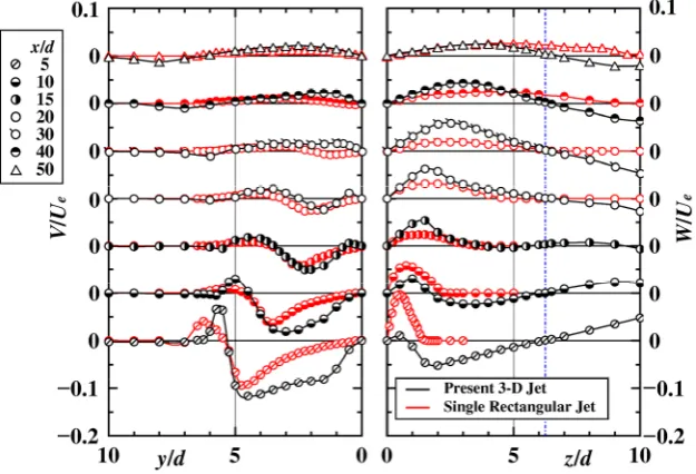
secondary flow velocity profiles on both the y and z axes between the present 3-D jet (Black) and the single rectangular jet (Red) by authors [12]. Here, the secondary flow profiles on both the y and z axes for the multiple rectangular jets by authors were not measured. Therefore, the results which were acquired by the single rectangular jet [12] were used.
The strong inward secondary flow on the y axis is shown in the extent from the section of x / d = 5 to 15. In the spanwise region of 0.5 ≤y / d ≤ 5.0 on the y axis at the section of x / d = 5, it is seen that the inward secondary flow of the present 3-D jet is promoted compared with that of the single rectangular jet (Red). On the other hand, the inward secondary flow on the z axis is produced at the section of x / d = 5 and10, but it is not found in the profiles of the single rectangular jet.
From the mentioned above, it is confirmed that the magnitude of the inward secondary flow on the y axis in the present 3-D jet is remarkably promoted compared with that of the single rectangular jet.
Fig. 3. Comparison of the streamwise variation of the longitudinal mean velocity profiles on both the y and z axes.
3.3 Variation of the contour plots of the longitudinal mean velocity
In this section, the streamwise variation of the whole flowfield at each constant section of x / d will be investigated by comparison of velocity contour plots
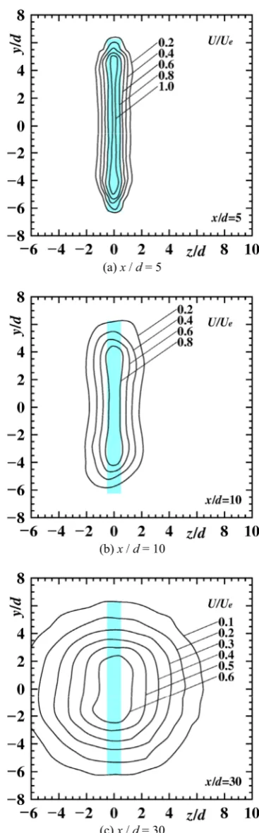
between the present 3-D jet and the single rectangular jet by authors [12]. Figures 5-(a), (b) and (c) show the streamwise variation of the velocity contour plots of the present 3-D jet, and figures 6-(a), (b) and (c) show the contour plots of the single rectangular jet for comparison.
(a) x / d = 5
(b) x / d = 15
(c) x / d = 30
Fig. 5. Streamwise variation of the contour plots of longitudinal mean velocity of the present 3-D jet.
(a) x / d = 5
(b) x / d = 10
(c) x / d = 30
Furthermore, the nozzle shape at the nozzle exit plane is painted blue, and a dotted line in figure 5 is drawn on the z / d = 6.25 slice plane which is the middle location between the present 3-D multiple rectangular nozzles.
The contour plot of x / d = 5 in figure 5-(a) indicates
the cruciform shape similar to the nozzle exit shape. The local maximum value (U / Ue ≅1.2) on the y axis is located at y / d = ±4.0 due to the inward secondary flows, and the jet width of U / Ue = 0.2 on the y axis is smaller than the rectangular nozzle length (12.5 d). On the other
(a) x / d = 5
(b) x / d = 15
(c) x / d = 30
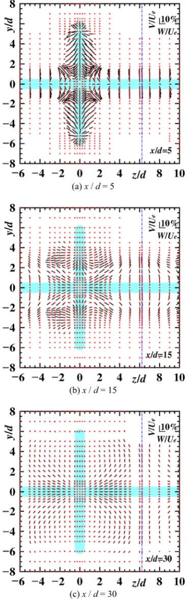
Fig. 7. Streamwise variation of the secondary flow vectors of the present 3-D jet at the three streamwise sections.
(a) x / d = 5
(b) x / d = 10
(c) x / d = 30
hand, the contour plot of the single rectangular jet at x / d = 5 also takes the local maximum value (U / Ue > 1.0) near y / d = ±4.0 on the y axis, and the jet width of U / Ue = 0.2 on the y axis is almost equal to the rectangular nozzle length.
The jet width (U / Ue = 0.2) on the y axis at x / d = 15 of the present 3-D jet is narrower than that at x / d = 5 because of the inward secondary flow, but the jet width in the y direction on the z / d = 6.25 slice plane is large compared with that at x / d = 5. The width in the z direction of the single rectangular jet at x / d = 10 expands compared with that at x / d = 5, but the width of U / Ue = 0.2 on the y axis is almost the same value.
Furthermore, the jet width (U / Ue = 0.2) of the present 3-D jet on the y axis at x / d = 30 is almost the same with that at x / d = 15 because there is no inward secondary flow on the y axis as shown in figure 4. However, the jet width (U / Ue ≤0.2) on the z / d = 6.25 slice plane of the present 3-D jet at x / d = 30 is larger than that on the y axis.
3.4 Variation of the secondary flow vectors
Figures 7-(a), (b) and (c) show the secondary flow vectors of the present 3-D jet, and the results of the secondary flow vectors of the single rectangular jet by authors [13] are shown in figures 8-(a), (b) and (c) for comparison. In this section, the feature of the promoted secondary flow velocity of the present 3-D jet will be clarified.
At the section of x / d = 5 for the present 3-D jet, the
inward secondary flows are confirmed in both the region of y / d ≤5.25 on the y axis and of z / d ≤6.00 on the z axis. As a result, the outward secondary flow is produced in the direction of y = ±z axes. The magnitude of the secondary flow velocity along the y axis is larger than that of the single rectangular jet, and it is seen that the inward secondary flow of the present 3-D jet is fairly promoted compared with that of the single rectangular jet as shown in figure 4.
The inward secondary flow velocity at the section of x / d = 15, is still found on the y axis near the jet centre region, but the extent of the inward secondary flow velocity becomes narrower than that at x / d = 5. The other hand, the inward secondary flow velocity in the region along the z axis is not found.
At the section of x / d = 30 of the present 3-D jet, there is no inward secondary flow velocity on both the y and z axes.
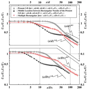
3.5 Variation of the velocity scale
The streamwise variation of the mean velocity scales along the x axis (y / d = z / d = 0) and the middle location (y / d = 0 and z / d = 6.25) for the present 3-D jet, is shown in figure 9. Here, the result of the multiple rectangular jets by authors is also indicated for comparison. The streamwise distance x of the upper section and the lower section of figure 9 was normalized by the nozzle width d and D2, respectively. The reason of the adaption of the length scale D2 is that this length scale is made from the total nozzle exit area of each
dimensional jet and is recognized as a suitable length scale for the three-dimensional jet which has each various shape [14]. The value of D2 for the present 3-D jet is equal to 1.90 d, on the other hand, the value of the multiple rectangular jets (S / d = 12.5) is equal to 0.983 d.
In the upper section, the potential core length of the present 3-D jet (Black) exists until the section of x / d = 28. This result shows that the potential core length of the present 3-D jet is completely longer than that of the multiple rectangular jets. For the case using the length scale D2, the velocity scale (Uox / Ue) (Black) on the x axis for the present 3-D jet shows the potential core region until the section of x / D2 = 14, this result is 2.3 times longer than that of the multiple rectangular jets (x / D2 = 6). This result is recognized as that the inward secondary flow is produced on the both axes in the initial region (cross shaped nozzle), and the advection transport of the mean kinetic energy (V ⋅ (U2 / 2) / y on the y axis, W ⋅ (U2 / 2) / z on the z axis) is promoted on both the y and z axes by using the method of running through transversely with a two-dimensional jet perpendicular to the multiple rectangular jets.
From the result mentioned above, it is clarified that the decay rate of the velocity scale on the x axis is strongly repressed, and the potential core region is extended extremely, compared with the multiple rectangular jets.
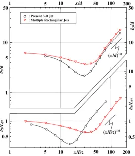
3.6 Variation of the length scale
The streamwise variation of the half velocity width on the y axis (rectangular nozzle axis) of both the present 3-D jet and the multiple rectangular jets by authors, will be compared in figure 10. Here, the horizontal axis x and the vertical axis by are normalized by the nozzle width d in the upper section of figure 10. On the other hand in the lower section of figure 10, the horizontal axis x is normalized by D2, and the vertical axis by is normalized by the half length of the rectangular nozzle length Lye.
The half velocity width by / d (Black) on the y axis of the present 3-D jet decreases from the value (by / d = 5.36) at x / d = 5 to the minimum value (by / d = 2.21) at x / d = 30. On the other hand, the result of by / d (Red) of the multiple rectangular jets decreases from the value (by / d = 6.15) at x / d = 2 to the minimum value (by / d = 3.74) at x / d ≅30. Comparing these results, the decreasing rate of by / d (Black) for the present 3-D jet is larger than that of the multiple rectangular jets (Red). From this result, it is confirmed that the development of the half velocity width on the y axis for the present 3-D jet, is suppressed remarkably compared with that of the multiple rectangular jets from the initial region to the CD region.
The minimum value of the half velocity width by which is normalized by the half-length Lye (= 6.25 d), will
be examined. The value of by / Lye (Black) is 0.354 at x / D2 = 15.7 for the present 3-D jet, and the value of by / Lye (Red) is 0.60 at x / D2 ≅ 30 for the multiple rectangular jets. From this result, it is seen that the magnitude of the length scale on the y axis for the present 3-D jet is 41% smaller than that for the multiple rectangular jets.
From the mentioned above, it is clear that the developing rate of the half velocity width by as the length scale on the rectangular nozzle axis, from the initial region to the CD region for the present 3-D jet, is remarkably suppressed compared with that of the multiple rectangular jets, by using the method of running through transversely with a two-dimensional jet perpendicular to the multiple rectangular jets, even if the length scale was normalized by either nozzle width d or D2.
4 Conclusion
The object of this experiment is to operate both the velocity scale and the length scale of the multiple rectangular jets. To resolve this problem, the method of running through transversely with a two-dimensional jet perpendicular to the multiple rectangular jets, was adapted. From the experiment, the results obtained are as follows:
(1) In this initial region of the present 3-D jet, the magnitude of the inward secondary flow on the rectangular nozzle axis (y axis) is remarkably promoted by a two-dimensional jet compared with that of the rectangular jet. Furthermore, the inward secondary flow in the initial region on the z axis of the present 3-D jet is produced.
(2) The decay rate of the velocity scale (Uox / Ue) on the x axis near the nozzle initial region is remarkably suppressed, and the potential core length is extended 2.3 times longer than that of the multiple rectangular jets, even if the velocity scale was normalized by either nozzle width d or length scale D2.
(3) The developing rate of the half velocity width by as the length scale on the rectangular nozzle axis from the initial region to the CD region for the present 3-D jet, is remarkably suppressed compared with that of the multiple rectangular jets.
References
1. Lilley, G. M., Aeronautical Journal, 88-875, 213-223 (1984)
2. Bevilaqua, P. M., Journal of Aircraft, 11-6, 348-354 (1974)
3. Lummus, J. R., Journal of Aircraft, 18-4, 245-251 (1981)
4. Krothapalli, A., Baganoff, D. and Karamcheti, K., AIAA Journal, 18-8, 945-950 (1980)
5. Marsters, G. F., AIAA Journal, 19-2, 148-152 (1981) 6. Krothapalli, A., Baganoff, D. and Karamcheti, K.,
Journal of Fluid Mechanics, 107, 201-220 (1981) 7. Yu, S., Japanese patent disclosure 2003-268523
(2003) (in Japanese)
8. Fujita, S. and Osaka, H., Transactions of the Japan Society of Mechanical Engineers, Series B, 53-488, 1142-1149 (1987) (in Japanese)
9. Fujita, S., Harima, T. and Osaka, H., Transactions of the Japan Society of Mechanical Engineers, Series B, 65-631, 905-911 (1999) (in Japanese)
10. Fujita, S., Harima, T. and Osaka, H., Transactions of the Japan Society of Mechanical Engineers, Series B, 72-717, 1159-1165 (2006) (in Japanese)
11. Fujita, S., Harima, T. and Osaka, H., Transactions of the Japan Society of Mechanical Engineers, Series B, 70-695, 1717-1724 (2004) (in Japanese)
12. Fujita, S., Harima, T. and Osaka, H., Fluid Structure Interaction V, WIT press, 61-70 (2009)
13. Fujita, S. and Harima, T., Transactions of the Japan Society of Mechanical Engineers, 80-820 (2014) (in Japanese)