DOI: 10.1051/epjconf/20147903001 C
Owned by the authors, published by EDP Sciences, 2014
MYRRHA: A multipurpose nuclear research facility
P. Baeten, M. Schyns, Rafaël Fernandez, Didier De Bruyn and Gert Van den Eynde Belgian Nuclear Research Center (SCK•CEN), Mol, Belgium
Abstract. MYRRHA (Multi-purpose hYbrid Research Reactor for High-tech Applications) is a multipurpose research facility currently being developed at SCK•CEN. MYRRHA is based on the ADS (Accelerator Driven System) concept where a proton accelerator, a spallation target and a subcritical reactor are coupled. MYRRHA will demonstrate the ADS full concept by coupling these three components at a reasonable power level to allow operation feedback.
As a flexible irradiation facility, the MYRRHA research facility will be able to work in both critical as subcritical modes. In this way, MYRRHA will allow fuel developments for innovative reactor systems, material developments for GEN IV and fusion reactors, and radioisotope production for medical and industrial applications. MYRRHA will be cooled by lead-bismuth eutectic and will play an important role in the development of the Pb-alloys technology needed for the LFR (Lead Fast Reactor) GEN IV concept.
MYRRHA will also contribute to the study of partitioning and transmutation of high-level waste. Transmutation of minor actinides (MA) can be completed in an efficient way in fast neutron spectrum facilities, so both critical reactors and subcritical ADS are potential candidates as dedicated transmutation systems. However critical reactors heavily loaded with fuel containing large amounts of MA pose reactivity control problems, and thus safety problems. A subcritical ADS operates in a flexible and safe manner, even with a core loading containing a high amount of MA leading to a high transmutation rate.
In this paper, the most recent developments in the design of the MYRRHA facility are presented.
1. Introduction
MYRRHA (Multi-purpose hYbrid Research Reactor for High-tech Applications) is the flexible experimental accelerator driven system (ADS) in development at SCK•CEN. MYRRHA is able to work both in subcritical (ADS) as in critical modes. In this way, MYRRHA should target the following applications catalogue:
• To demonstrate the full ADS concept by coupling the three components (accelerator, spallation target and sub-critical reactor) at reasonable power level to allow operation feedback and scalability to an industrial demonstrator;
• To allow the study of the efficient technological transmutation of high-level nuclear waste, in particular minor actinides that would request high fast flux intensity (>0.75 MeV=1015n/cm2.s);
• To be operated as a flexible fast spectrum irradiation facility allowing for:
◦ fuel developments for innovative reactor systems, which need irradiation rigs with a representative flux spectrum, a representative irradiation temperature and high total flux levels (tot=5·1014to
1015n/cm2.s); the main target will be GEN IV systems which require fast spectrum conditions;
◦ material developments for GEN IV systems, which need large irradiation volumes (3000 cm2)
with high uniform fast flux level (>1 MeV=∼5·1014n/cm2.s) in various irradiation positions,
representative irradiation temperature and representative neutron spectrum conditions; the main target will be fast spectrum GEN IV systems;
◦ material developments for fusion reactors which need also large irradiation volumes (3000 cm3)
with high fast flux level (>1 MeV =∼5·1014n/cm2.s) with low gradients, a representative and
controled irradiation temperature and a representative ratio appm He/dpa(Fe)=10; ◦ radioisotope production for medical and industrial applications by:
holding a backup role for classical medical radioisotopes;
focusing on R&D and production of radioisotopes requesting very high thermal flux levels
(thermal=2 to 3·1015n/cm2.s) due to double capture reactions;
◦ industrial applications, such as Si-doping that needs a thermal flux level depending on the desired irradiation time: for a flux levelthermal=1013n/cm2.s, an irradiation time in the order of days is
needed and for a flux level ofthermal=1014n/cm2.s, an irradiation time in the order of hours is
needed to obtain the required specifications.
MYRRHA has started from the ADONIS project (1995 – 1997), which was the first project at SCK•CEN where the coupling between an accelerator, a spallation target and a subcritical core was studied. ADONIS was a small irradiation facility, having the production of 99Mo as its single objective. In
1998, the ad-hoc scientific advisory committee recommended extending the purpose of the ADONIS machine to become a material testing reactor for material and fuel research, to study the feasibility of transmutation of minor actinides and to demonstrate the principle of the ADS at a reasonable power scale. Since 1998, the project is called MYRRHA.
In 2005 MYRRHA consisted of a proton accelerator delivering 350 MeV * 5 mA to a windowless spallation target coupled to a subcritical fast core of 50 MWth. This 2005 version is the “MYRRHA –
draft 2” design [1]. This 2005 design was used as a starting base within the FP6 EUROTRANS integrated project [2], which resulted in the XT-ADS [3] (Experimental Demonstration of the Technical Feasibility of Transmutation in an Accelerator Driven System) design, where a linear proton accelerator delivers a 600 MeV * 3.2 mA beam into the spallation target. The reactor power of XT-ADS was 57 MWth.
The XT-ADS design was taken as a starting point for the work performed in the FP7 CDT project [4], which resulted in the MYRRHA-FASTEF (MYRRHA Fast Spectrum Transmutation Experimental Facility) design. The MYRRHA design has now entered into the Front End Engineering Design (FEED) Phase. A tendering process has been launched to select a consortium of engineering companies to support the FEED. The current design of MYRRHA-FASTEF is described further down in this paper.
2. The MYRRHA accelerator
Accelerator reliability is a crucial issue for the operation of an ADS. A high reliability is expressed by a long Mean Time Between Failure (MTBF), which is commonly obtained by a combination of over-design and redundancy. On top of these two strategies, fault tolerance in the high energy section of the Linac (above 17 MeV) must be implemented to obtain the required MTBF. Fault tolerance will allow the accelerator to recover the beam within a beam trip duration tolerance after failure of a single cavity. In the MYRRHA case, the beam trip duration tolerance is 3 seconds. Within an operational period of MYRRHA of 3months the number of allowed beam trips exceeding 3 seconds must remain under 10, shorter beam trips are allowed without limitations. The combination of redundancy and fault tolerance should allow obtaining a MTBF value in excess of 250 hours to meet the required number of beam trips per operation cycle of 3 months.
At present proton accelerators with megawatt level beam power in CW mode only exist in two basic concepts: sector-focused cyclotrons and linear accelerators (linacs). Cyclotrons are an attractive option with respect to construction costs, but they don’t have any modularity which means that a fault tolerance scheme cannot be implemented. Also, an upgrade of its beam energy is not a realistic option. A linear accelerator, especially if made superconducting, has the potential for implementing a fault tolerance scheme and offers a high modularity, resulting in the possibility to recover the beam within a short time and increasing the beam energy.
3. The MYRRHA core and primary system
The main components/systems of the current MYRRHA-FASTEF design are of the same MYRRHA/XT-ADS type, as defined within the EUROTRANS project, with only increased size. The primary and secondary systems have been designed to evacuate a maximum core power of 100 MWth. All the MYRRHA-FASTEF components are optimized for the extensive use of the remote handling system during components replacement, inspection and handling.
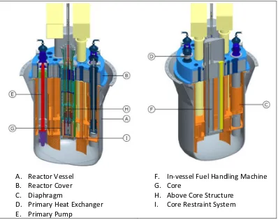
Since MYRRHA-FASTEF is a pool-type ADS, the reactor vessel houses all the primary systems. In previous designs of MYRRHA, an outer vessel served as secondary containment in case the reactor vessel leaks or breaks. In the current design, the reactor pit fulfils this function, improving the capabilities of the reactor vault air cooling system. The vessel is closed by the reactor cover which supports all the in-vessel components. A diaphragm inside the vessel acts to separate the hot and cold LBE plenums, to support the In-Vessel Fuel Storage (IVFS) and to provide a pressure separation. The core is held in place by the core support structure consisting of a core barrel and a core support plate. Figure1shows vertical cut sections of the MYRRHA-FASTEF reactor showing its main internal components.
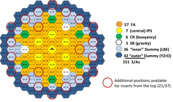
At the present state of the design, the reactor core (Fig.2) consists of mixed oxide (MOX) fuel pins, typical for fast reactors. A major change with respect to the previous version of the core is the switch from a windowless loop-type spallation target to a window beam tube-type spallation target. The previous version needed three central hexagons to house the spallation target while the present day design only needs one central hexagon. To better accommodate this central target, the fuel assemblies size is a little bit increased as compared to the MYRRHA/XT-ADS design. Consequently the In-Pile test Sections (IPS), which will be located in dedicated FAs positions, are larger in diameter giving more flexibility for experiments. Thirty seven positions can be occupied by IPSs or by the spallation target (the central one of the core in sub-critical configuration) or by control and shutdown rods (in the core critical configuration). This gives a large flexibility in the choice of the more suitable position (neutron flux) for each experiment.
A. Reactor Vessel
B. Reactor Cover
C. Diaphragm
D. Primary Heat Exchanger
E.
Primary Pump
F.
In-vessel Fuel Handling Machine
G. Core
H. Above Core Structure
I.
Core Restraint System
Figure 1. Section of the MYRRHA-FASTEF reactor.
of lead-bismuth eutectic (LBE) as coolant permits to lower the core inlet operating temperature (down to 270◦C) decreasing the risk of corrosion and allowing to increase the coreT. This together with the adoption of reliable and passive shutdown systems will permit to meet the high fast flux intensity target. As depicted in Fig.2, showing a critical core layout (with 7 central IPS) at the equilibrium of the fuel cycle, 37 positions are available for Multi-Functional Channels (MFC) that can host indifferently:
• fuel assembly and dummy, loaded from the bottom (in all the 151 positions); • IPS, Control and Scram rods, loaded from the top.
In subcritical mode the accelerator (as described in the previous section) is the driver of the system. It provides the high energy protons that are used in the spallation target to create neutrons which in their turn feed the subcritical core. The accelerator is able to provide a proton beam with energy of 600 MeV and a maximum current of 4 mA.
In subcritical mode the spallation target assembly, located in the central position of the core, brings the proton beam via the beam tube into the central core region. The spallation heat deposit is dissipated to the reactor primary circuit. The spallation module guarantees the barrier between the reactor LBE and the reactor hall and insures optimal conditions for the spallation reaction. The spallation module assembly is conceived as an IPS and is easily removable or replaceable.
Figure 2. Section of the MYRRHA-FASTEF core.
will be implemented by adopting the Control Rods, but they will be controlled manually only by the operator.
As in critical mode, two different kinds of dummy assemblies are foreseen (Fig.2):
• an internal ring surrounding the fissile zone made of LBE dummy assemblies (to increase neutron “reflection”);
• an external ring made of dummy assemblies having the same structure of FA with clads filled with YZrO pellets (to shield the core barrel).
The primary, secondary and tertiary cooling systems have been designed to evacuate a maximum thermal core power of 110 MW. The 10 MW more than the nominal core power account for the power deposited by the protons, for the power of in-vessel fuel and for the power deposited in the structures by-heating. The average coolant temperature increase in the core in nominal conditions is 140◦C with a coolant velocity of 2 m/s. The primary cooling system consists of two pumps and four primary heat exchangers (PHX).
The primary pumps shall deliver the LBE to the core with a mass flow rate of 4750 kg/s (453 l/s per pump). The working pressure of the pump is 300 kPa. The pump will be fixed at the top of the reactor cover, which is supposed to be the only supporting and guiding element of the pump assembly.
The secondary cooling system is a water cooling system while the tertiary system is an air cooling system. These systems function in active mode during normal operation and in passive mode in emergency conditions for decay heat removal.
The main thermal connection between the primary and secondary cooling systems is provided by the primary heat exchangers (Fig.3). These heat exchangers are shell and tube, single-pass and counter-current heat exchangers. Pressurized water at 200◦C is used as secondary coolant, flowing through the feed-water pipe in the centre of the PHX to the lower dome. All the walls separating the LBE and water plena (feed-water tube, lower dome and upper annular space) are double walled to avoid pre-heating of the secondary coolant and to prevent water leaking in the LBE in case of tube rupture.
Figure 3. Primary Heat Exchangers.
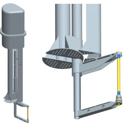
Figure 4. Primary Heat Exchangers.
convection. Ultimate DHR is done through the reactor vessel cooling system (RVACS, reactor vessel air cooling system) by natural convection.
Two fuel handling machines are used, located at opposite sides of the core (Fig.4). Each machine covers one side of the core. The use of two machines provides sufficient range to cover the necessary fuel storage positions without the need of an increase for the reactor vessel when only one fuel handling machine is used. Each machine is based on the well-known fast reactor technology of the “rotating plug” concept using SCARA (Selective Compliant Assembly Robot Arm) robots. To extract or insert the fuel assemblies, the robot arm can move up or down for about 2 meters. A gripper and guide arm is used to handle the FAs: the gripper locks the FA and the guide has two functions, namely to hold the FA in the vertical orientation and to ensure neighbouring FAs are not disturbed when a FA is extracted from the core. An ultrasonic (US) sensor is used to uniquely identify the FAs.
The in-vessel fuel handling machine will also perform in-vessel inspection and recovery of an unconstrained FA. Incremental single-point scanning of the diaphragm can be performed by an US sensor mounted at the gripper of the IVFHM. The baffle under the diaphragm is crucial of the strategy as it limits the work area where inspection and recovery are needed. It eliminates also the need of additional recovery and inspection manipulators, prevents items from migrating into the space between the diaphragm and the reactor cover, and permits side scanning.
4. Conclusion
SCK•CEN is proposing to replace its ageing flagship facility, the Material Testing Reactor BR2, by a new flexible irradiation facility, MYRRHA. Considering the international and European needs, MYRRHA is conceived as a flexible fast spectrum irradiation facility able to work in both sub-critical and critical mode. The objective of the project is to create an international irradiation research facility in a European Research Area on Experimental Reactors allowing top study the behaviour of structural
MYRRHA is now foreseen to be in full operation by 2023 and it will be operated as an Accelerator Driven Systems to demonstrate the ADS technology and the efficient demonstration of MA in sub-critical mode and will be able to be run in sub-critical mode. As a fast spectrum irradiation facility, it will address fuel research for innovative reactor systems, material research for GEN IV systems and for fusion reactors, radioisotope production for medical and industrial applications and industrial applications, such as Si-doping. Being based on heavy liquid metal coolant technology, MYRRHA will also act as the European Technology Pilot Plant for the development of the Lead Fast Reactor.
References
[1] H. Aït Abderrahim, D. De Bruyn et al., MYRRHA Project – Technical Description, SCK•CEN Report reference AND/HAA/DDB/3900.B043000/85/07-17bis, April 2007
[2] EU Integrated Project EUROTRANS, contract nr. FI6W-CT-2004-516520
[3] D. De Bruyn, S. Larmignat, A. Woaye Hune, L. Mansani, G. Rimpault and C. Artioli, Accelerator Driven Systems for Transmutation: Main Design Achievements of the XT-ADS and EFIT systems within the FP6 IP-EUROTRANS Integrated Project, International Congress on Advances in Nuclear Power Plants (ICAPP’10), San Diego (California, USA), June 13–17, 2010, American Nuclear Society (2010)