Comparison of heat transfer in straight and corrugated minichannels with
two-phase flow
P. Peukert1,2,3,,aand J. Hrub´y1,b
1 Institute of Thermomechanics AS CR, v. v. i., Dolejˇskova 1402/5, 182 00 Praha 8 2 KEZ, TUL, FS, Studentsk´a 2, 461 17 Liberec, Czech Republic
3 V ´UTS, Sv´arovsk´a 619, 460 01 Liberec, Czech Republic
Abstract. Measurements of heat transfer rates performed with an experimental condensation heat exchanger are reported for a corrugated minichannel tube and for a straight minichannel tube. The two cases were compared at same flow regimes. The corrugation appears advantageous for relatively low steam pressures and flow rates where much higher heat transfer rates were observed close to the steam entrance, thus allowing shortening the heat exchanger with the associated advantages of costs lowering and smaller built-up space. At high steam pressures and high flow rates both tubes performed similarly.
1 Introduction
The industry demands reliable condensation heat exchang-ers with high heat transfer rates at constantly decreasing di-mensions and lower material costs. An important direction of development is the usage of mini and micro-channels. Without microchannels, no compact car air-condition sys-tems is possible. Also of industrial interest are compact heat exchangers ranging from simple household heating to sophisticated technological processes. Some applications of the mini and microchannels are around a few decades, but a theoretical basis and a pool of experimental data is hardly available.
2 Mini and microchannels
A simple classification of the heat transfer devices in few groups by scale was suggested by Kandlikar [2]: conven-tional channels are with characteristic dimension above 3 mm, minichannels from 200μm up to 3 mm and mi-crochannels from 10μm to 200μm. However, for various processes and fluids that dividing is not sufficient.
In case of the two-phase flow, more relevant criteria fol-low from considering important processes occurring along the channel. The balance of the shear, surface tension and gravity forces is the most important factor for the distinc-tion between the convendistinc-tional and microchannel effects. Whereas in the convectional scales the gravity force plays the major rule, with the downsizing the shear and surface tension forces become most important.
From the view of the fluid a criterion recommended by Seriyawaet al.is that the hydraulic diameterDhof the channel should by smaller than the Laplace constantLgiven by equation 1 as presented Garimella [2].
L=
σ ρL−ρV
(1)
a e-mail:[email protected]
b e-mail:[email protected]
In equation 1,σstands for surface tension,ρLdensity of the liquid, and ρV density of the vapor. For a water-steam mixture, as microchannel we can call channels from 3 mm downward. Kew and Cornwell as Garimella men-tioned [2] introduced the confinement numberCoby equa-tion 2, which should be below 0.5 to meet the requirement. So the transient diameter is halved.
Co= L
Dh =
σ ρL−ρV
Dh
(2)
It is not clear where the transition border for the mi-crochannel effects occurs. Especially at the border area, the estimation of the possible effects should be taken with care.
3 Experimental setup
The experimental setup consist of two major parts. The first part is an unique steam generating system [5], which sup-plies the heat exchanger with steam at required properties. The second part represents the experimental condensation heat exchanger with all accessories.
The experimental condensation heat exchanger was de-veloped to study the heat transfer occurring in industrial heat exchangers (figure 1). A special design of the experi-mental exchanger allows a detailed study of the heat transfer processes. A common counterflow arrangement was used.
The most important part of the experimental heat ex-changer is a minichannel tube, according to the basic clasi-fication mentioned by Kandlikar [2]. For the experiments were used two tubes, which are depicted in figure 2. Both tubes have the same inner diameterdin=2 mm, outer diam-eterdout=4 mm and lengthL. One tube is corrugated with an average eccentricitye=3 mm and a pitchp=15 mm. The second tube is straight. Both tubes had a narrowing to a short smaller tube at the condensate outlet serving as a pressure drop.
The minichannel tube is inserted into a larger brass tube. This tube can be equipped with a tightly inserted silicon C
Owned by the authors, published by EDP Sciences, 2014
Figure 1:Industrial condensation heat exchanger
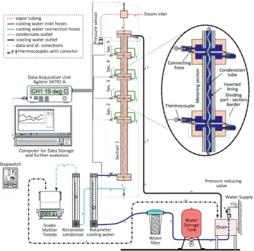
hose of selected wall thickness to simulate different outer tube inner diameterDin. For experiments mentioned in this paper, wasDin = 8 mm, which corresponds to the same hydraulic diameterDhof the outer cross-section. The outer tube was divided into five sections. The upper four sections (sec.2-5) are equally long. The lowest section (sec.1) has the same length as the the upper four combined. This way of dividing was chosen because for most cases the conden-sation is present within the upper half of the heat exchanger. At the transition between the sections, a dividing part is installed. An overview of the experimental heat exchanger with its accessories is depicted in figure 3.
Slightly superheated steam flows from the top into the minichannel condensation tube. At the entrance the pres-sure is meapres-sured with the sensor Druck PMP 1400 and the temperature with a T-type thermocouple. All thermocouples installed at the experimental heat exchanger are T-type. The steam condenses inside the minichannel tube and exits. At the exit another thermocouple is located to measure the con-densate outlet temperature. From here the concon-densate flows into to the Omega FL-092-04-N-ST rotameter equipped with a control valve. After passing the the rotameter, the condensate is lead for a more precise flow rate measurement
Figure 2:Side by side scheme of of the straight and corugated minichannel condensation tube
to a vessel positioned on the Mettler Toledo PR 8002 Delta Range scales or to a drain during the setup stabilization times.
The cooling water to the heat exchanger is provided from the public water supply. To provide a constant cooling water flow, a reducing valve and an air-pressurized storage tank are installed. The cooling water flow rate is measured with rotameter FL-044-40-N-CA equipped with a control valve serving to set the flow rate. To ensure that the fine sieve installed in the rotameter does not get blocked, a rough sieve is installed before the reducing valve and an additional fine filter is placed before the rotameter. The cooling water enters the heat exchanger from the bottom at a entry section where the temperature is measured. The water flows trough the section and at the section end the bulk temperature is measured. This is repeated in the following sections until the water enters the exit part, where the outlet temperature is measured and the water is lead to the drain.
The temperatures from the thermocouples and the signal of the pressure sensor were collected during the measure-ment via a data acquisition unit HP/Agilent 34401A and saved to the computer for further processing. The flow rates measured with the scales and rotameters were collected manually for every measurement.
4 The measurements
Figure 3:Scheme of the experimental heat exchanger setup
starts. The temperatures and inlet pressure were collected over two minutes to get satisfactory average values. The process is not entirely stationary. Some small (up to 10%) fluctuations could be observed at condensate flow rates and temperatures for specific flow regimes.1For most measure-ments, the fluctuations were negligible. The condensate was captured during the measurement to the vessel, which was later weighted and divided by the time measured by a stopwatch so an accurate average mass flow rate was obtained.
The measurements were done for absolute pressures from 2 to 6 bar with a step of 1 bar. The condensate flow rate was set to values corresponding to the rotameter reading of 35, 50, 75, 100, 125 and 150 mm, if the steam pressure was sufficient to provide such flow rate2For all combinations of pressure and condensate values, the cooling water flow rate was set to values corresponding to rotameter scale readings from 35 to 55 mm with a 5 mm step, from 60 to 120 mm with a 10 mm step and then the values of 135 and
1 The fluctuations emerged like pulsations especially at low
overpressures, about 2 bar and flow rates which were at 75 and 100 mm at condensate rotameter scale values and the lowest cool-ing water flow rates which ensure an outlet temperature below the boiling temperature.
2 As an example, the maximum flow rate scale value on the
rotameter, provided by the absolute pressure of 2 bar, was 100 mm, for a pressure of 3 bar was the scale value 125 mm.
Table 1:Corelation between rotameter scale values and volumetric flow rates litOmega.
Scale value Condensate Cooling water FL-092-04-N-ST FL-044-40-N-CA
(mm) (ml/min) (ml/min)
30 28 336
40 38 457
50 48 586
60 59 714
70 69 848
80 78 981
90 88 1117
100 96 1252
110 104 1392
120 113 1528
130 120 1652
140 127 1778
150 134 1881
150 mm. The lowest cooling water flow rate was set so that it provided a maximum temperature of 96◦C at its exit. In table 1, an approximate relation is given between the flow rate of condensate and cooling water to the rotameter scale value.
Figure 4:Histogram of of heat transfer to cooling water from the heat transfer get from steam/condensate.
8002 Delta Range scales and a stopwatch. All thermocou-ples were calibrated using the Ametek Jofra temperature calibrator.
5 Computations
Heat transfer rates for the experimental heat exchanger were computed from the measured temperature difference, mass flow rate and pressure. For computation of the total heat rate transfer from the condensing steam ˙Qtotal,C over the whole minichannel tube equation 3 is used.
˙
Qtotal,C=m˙ChS,in−hC,out (3) In equation 3, ˙mCis the condensate mass flow rate com-puted as ˙mC = mC/t, wheremC is the mass of the con-densate captured in the vessel during timet. The specific enthalpies for steamhS,inand condensatehC,outwere calcu-lated using the IAPWS-IF97) [3] formulation of thermody-namic properties of water and steam.
On the cooling water side, the heat transfer rate ˙Qi,CW was computed for every measuring section with equation 4. The specific enthalpieshi+0.5andhi−0.5represent with the indexes i+/- 0.5 the boarders of the section. For the com-putation ofh,the IAPWS-IF 97 was used again.hi−0.5 =
f(pi−0.5,Ti−0.5), where pi−0.5is the pressure at the section entrance andTi−0.5 is the bulk temperature at section en-trance. The index i+0.5 stands for the section exit values.
˙
Qi,CW=m˙CWt(hi+0.5−hi−0.5) (4) Even if the heat exchanger was very well insulated (The heat exchanger heat losses are less than 60 W.), some differences between the heat transfer rates ofdotQtotal,CW and ˙Qtotal,C occured. An distribution of the deviation of
dotQtotal,CWfromdotQtotal,Cis depicted in figure 4. It could be seen that most measurements are located within a devia-tion range of 5%. A deviadevia-tion of 10% is tolerated, higher values were sorted out. For estimation of fluid fraction de-velopment over the length in the minichannel, it is necessary to flatten the values of both heat transfer rates on one value. As the reference value was chosen the inner heat transfer, because its measurement is more precise over the whole range of all measurements. Equation 5 introduces an co-efficient, which is used later in equation 6 to compute the modified heat transfer for every section ˙Qi,k, which is valid for the inner minichannel tube.
mSis the steam mass fraction andmLthe liquid water mass fraction for a given control volume. To compute the steam quality on the section border its necessary to compute the total enthalpy flux at the boarder ˙Hi−0.5 for the fluid inside the minichannel by equation 8.
˙
Hi−0.5=H˙i+0.5−Q˙i,k (8) In equation 8, i=5..2 represents the section number. The specific enthalpy for every section boarderhi+0.5 is calculated using equation 9 for i=1..4.
hi+0.5= ˙
Hi+0.5 ˙
mC
(9)
Finally, the steam quality is given by equation 10. It is necessary to mention that in the present computation we neglect the marginal subcooling of liquid water from the saturation state and assumes a constant temperature of the the fluid inside the minichannel cross-section.
x=hi+0.5−hsat L hsat S−hsat L
(10)
To have an qualitative heat transfer comparison param-eter for all sections and all measured cases, because of different section lengths, the total heat transfer rate ˙Qi,k for a given section was divided by the section lengthLiin equation 11.
˙
Qi,L=
kQQ˙i,k
Li
(11)
6 Results
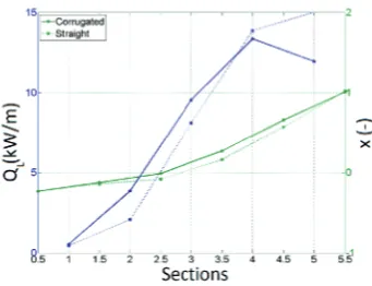
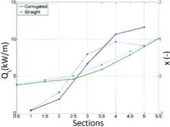
A lot of measurements were done for the mentioned cases. Only a brief selection of charts showing a comparison be-tween the corrugated and the straight minichannel tube in different working regimes will follow. All charts from fig-ure 5 to ??show on the x-axis the number of the given section (integer value)and its boarder the (0.5 values). On the left y-axis, the total heat transfer rate divided by sec-tion length ˙Qi,Lis shown and on the right y-axis the steam qualityxis shown. The solid lines represent the corrugated and the dotted the dashed lines the minichannel tube. The blue line, with points on the integer numbers is the heat transfer rate on 1 m and the green one, with points at the half values stands for the steam quality. The steam quality over 1 means superheated steam and bellow 0 subcooled water.
Figure 5:Chart for the case of steam pressure 3 bar, condensate scale flow rate value 100 mm and a cooling water scale flow rate value 90 mm
Figure 6:Chart for the case of steam pressure 4 bar, condensate scale flow rate value 100 mm and a cooling water scale flow rate value 90 mm
to condense immediately in section 5. The heat transfer is about 80% higher for the corrugated tube than for the straight one. At section 2 the difference shrinks to a favour of 55% for the corrugated to straight tube. Section 3 marks the end of condensation for the corrugated tube so the heat transfer reduces significantly, whereas the straight tube still condenses. For the straight tube a further heat transfer rate increase is evident. This could be caused via waves which could occur in the condensate film at some section part [1]. At section 2 and 1 only a further cooling down of the con-densate is present for the corrugated tube. At section 2 is for the straight tube, the steam-liquid water mixture is still present. However, a decrease of the heat transfer occurs because the condensate forms a thicker insulation layer. At section 1 a small rest of the steam condenses and then the liquid is further subcooled. Figure 5 shows and impressive enhancement of the heat transfer due to the corrugation of the minichannel tube.
The picture collection from figure 5 to 8 shows the tendencies with increasing the steam inlet pressure. With an increase of the pressure the heat transfer also increases significantly and both heat transfer curves align each other. Somewhat strange looks the case in picture 8 where the heat transfer in section 5 is slightly higher and in section 4 slightly lower for the straight tube than for the corrugated one.
Figures 6 and 9 to 11 show the tendency with the in-crease of the cooling water flow rate. A migration of the
Figure 7:Chart for the case of steam pressure 5 bar, condensate scale flow rate value 100 mm and a cooling water scale flow rate value 90 mm
Figure 8:Chart for the case of steam pressure 6 bar, condensate scale flow rate value 100 mm and a cooling water scale flow rate value 90 mm
Figure 9:Chart for the case of steam pressure 4 bar, condensate scale flow rate value 100 mm and a cooling water scale flow rate value 100 mm
more intensive heat flux to the upper section could be ob-served.
Figure 10:Chart for the case of steam pressure 4 bar, condensate scale flow rate value 100 mm and a cooling water scale flow rate value 135 mm
Figure 11:Chart for the case of steam pressure 4 bar, condensate scale flow rate value 100 mm and a cooling water scale flow rate value 150 mm
Figure 12:Chart for the case of steam pressure 4 bar, condensate scale flow rate value 75 mm and a cooling water scale flow rate value 50 mm
7 Conclusions
The experiments showed interesting differences between the heat transfer characteristics for an straight and a corrugated minichannel tube. It is obvious from the results that the corrugated minichannel tube provides a great advantage for steam input of lower pressure values and lower flow rates. At higher steam pressures, the difference is almost invisible. A reason for that behavior could be found in the mi-crochannel effect, due to the higher surface tension for lover water temperatures so that some water bridges could oc-cur between steam “slugs”. Trough this effect, a significant
Figure 13:Chart for the case of steam pressure 4 bar, condensate scale flow rate value 150 mm and a cooling water scale flow rate value 90 mm
pressure loss occurs, so that the saturation temperature dra-matically decreases and the heat transfer rate decreases too.
A reason why the heat transfer rate distributions over the length get similar at higher pressure could be found in the pressure itself. Higher steam pressure means also a perceptibly temperature increase of the steam and also the saturated water. In combination with higher steam flow rates also the condensate is more turbulent and so a better heat transfer could appear.
In the end could be mentioned that the corrugated tube has sense from the point of heat transfer for lower flow rates and steam pressures. So the whole heat exchanger could be more compact. For higher pressures and flow rates, the corrugation is not needed. But another aspect is the mechanical strength, which better for the corrugated tube.
8 Acknowledgements
The authors gratefully acknowledge the support by grant No. P101/11/1593 by the Czech Science Foundation and insti-tutional support RVO:61388998 and the SGS 28000 by the Technical University of Liberec. The corrugated minichan-nel tubes were kindly provided by the company Glazer, Cheb, Czech Republic. Also gratefully acknowledged is the technical assistance by Bohuslav ˇSm´ıd mechanical design, Miroslav Pavelka (electrical design), Jiˇr´ı Hykl (chemistry) and others.
References
1. H. D. Baehr, K. Stephan,Heat and Mass Transfer
(Springer, 2006)
2. S. Kandlikar, S. Garimella,Heat transfer and fluid flow in minichannels and microchannels(Elsevier Ltd., 2006) 3. W. Wagner , J. R. Cooper, A. Dittmann, J. Kijima, H. J. Kretzchmar, A. Kurse, R. Mareˇs, K. Oguchi, H. Sato, I. St¨ocker, O. ˇSifner, Y. Takaischi, I. Tanishita, J. Tr¨ubenbach, Th. Willkommen,Revised Release on Indus-trial Formulation 1997 for the Thermodynamic Properties of Water and Steam(2007)
4. Omega Inc., Corelation data sheat for the rotameter FL-092-04-N-ST and FL-044-40-N-CA(2010)