University of South Carolina University of South Carolina
Scholar Commons
Scholar Commons
Theses and Dissertations
Summer 2019
Enhancing Thermal-Hydraulic Performance of Parallel and
Enhancing Thermal-Hydraulic Performance of Parallel and
Counter Flow Mini-Channel Heat Sinks Utilizing Secondary Flow: A
Counter Flow Mini-Channel Heat Sinks Utilizing Secondary Flow: A
Numerical and Experimental Study
Numerical and Experimental Study
Amitav TikadarFollow this and additional works at: https://scholarcommons.sc.edu/etd
Part of the Mechanical Engineering Commons
Recommended Citation Recommended Citation
Tikadar, A.(2019). Enhancing Thermal-Hydraulic Performance of Parallel and Counter Flow Mini-Channel Heat Sinks Utilizing Secondary Flow: A Numerical and Experimental Study. (Master's thesis). Retrieved from https://scholarcommons.sc.edu/etd/5453
This Open Access Thesis is brought to you by Scholar Commons. It has been accepted for inclusion in Theses and Dissertations by an authorized administrator of Scholar Commons. For more information, please contact
E
NHANCINGT
HERMAL-H
YDRAULICP
ERFORMANCE OFP
ARALLEL ANDC
OUNTERF
LOWM
INI-C
HANNELH
EATS
INKSU
TILIZINGS
ECONDARYF
LOW:
A
N
UMERICAL ANDE
XPERIMENTALS
TUDYby
Amitav Tikadar
Bachelor of Science
Bangladesh University of Engineering & Technology, 2015
Submitted in Partial Fulfillment of the Requirements
For the Degree of Master of Science in
Mechanical Engineering
College of Engineering and Computing
University of South Carolina
2019
Accepted by:
Jamil A. Khan, Director of Thesis
Chen Li, Reader
Titan C. Paul, Reader
© Copyright by Amitav Tikadar, 2019
DEDICATION
This work is dedicated to the memory of my best friend, Mr. Mahamudul Hossain
Sohel, who always inspired me through his hard work and brilliance. You are gone, but
ACKNOWLEDGMENT
The author would like to express his sincere gratitude to his advisor, Prof. Jamil A.
Khan, for his continuous support, encouragement, motivation, and guidance throughout all
phases of this M.S. study in all these years. It has been a great privilege and honor for the
author to work with him.
The author would like to thank his defense committee members, Prof. Chen Li, and
Prof. Titan C. Paul, for their comments, suggestions, and time for reviewing this thesis.
The author would also like to thank his colleagues in the “Enhanced Heat Transfer
Lab,” Dr. Azzam S. Salman, Mr. Nabeel M. Abdulrazzaq, Mr. Nobbel Aumbee, and Mrs.
Sowmya Raghu for their invaluable suggestions and comments during the research. Special
thanks to Mr. Saad K. Oudah for his invaluable help to build up the experimental setup.
The author would also like to acknowledge Dr. A.K.M. Monjur Morshed for his continuous
support.
Finally, the author would like to thank his Father Dinesh Chandra Tikadar, Mother
Mukti Rani Tikadar, all elder sisters Mrs. Binita Tikadar, Mrs. Eti Tikadar, and Mrs. Dipa
ABSTRACT
Continual growth of hydraulic and thermal boundary layers along stream wise
direction in conventional straight fin mini-channel heat sink causes gradual deterioration
of their thermal performance. To enhance thermal-hydraulic performance by breaking and
redevelopment of the boundary layers, this research aims to introduce a novel
inter-connected mini-channel sinks. Two inter-connectors were positioned transversely between
two adjacent mini-channels, which segmented the flow domain into three zones. Secondary
flow was generated through the inter-connectors utilizing the pressure difference of the
adjacent channels resulting in hydraulic and thermal boundary layers disruption and hence
enhanced thermal-hydraulic performance of the mini-channel heat sink was achieved.
Firstly, this present work attempts to numerically analyze and compare the effects
of inter-connectors width on the heat transfer and fluid flow behaviors of parallel and
counter flow mini-channel heat sinks. Five different inter-connector width (case 1-5) were
considered for a fixed inter-connector location (zones length). A corresponding
conventional parallel flow mini-channel heat sink was chosen as the base case in contrast
to the newly proposed inter-connected mini-channel heat sinks. The length, height, and
width of the considered mini-channel heat sink were 26 mm, 0.5 mm, and 1.5 mm
respectively, which provides a hydraulic diameter of 750 μm. Water was employed as the
coolant, and the flow was in the single-phase regime under laminar flow condition at
temperature, friction factor, overall Nusselt number (𝑁𝑢), and thermal resistance were
calculated to evaluate the overall performance of the inter-connected mini-channel heat
sink. Finally, the performance of the inter-connected mini channel was compared with the
conventional parallel flow mini-channel by calculating the performance evaluation criteria
(PEC). The results show that the inter-connector has negligible effect on the overall
performance of the parallel flow mini-channel heat sinks because of the almost no
transverse flow through the inter-connectors whereas, inter-connector has significant effect
on the overall performance of the counter flow mini-channel heat sinks. For the counter
flow mini-channel heat sink and for the highest considered inter-connectors width (case 5),
Nu was enhanced by a maximum of 36% at 𝑅𝑒 = 1044 as compared to the conventional
parallel flow mini-channel while a maximum of 31.13% reduction in friction factor was
recorded at 𝑅𝑒 = 150. The PEC of the inter-connected counter flow mini-channel heat
sink (case 5) went up to 1.33, and its value shows an increasing trend with as 𝑅𝑒 increases.
Secondly, to examine the combined effect of the inter-connectors width and
location, i.e., zones length on the thermal-hydraulic characteristics of the counter flow
mini-channel heat sink, the present numerical studies were carried out for nine different
cases (case 1-9) by varying inter-connectors width and location. The results show that the
amount of secondary flow reduces gradually as 𝑅𝑒 increases for any particular
inter-connectors location and width. At the lowest considered 𝑅𝑒(𝑅𝑒 = 150), a maximum value
of PEC was achieved to ~1.22 for the highest length of zone 1 and 3 and the lowest
inter-connectors width (case 7), while at the highest 𝑅𝑒 (𝑅𝑒 = 1044), the maximum PEC value
(~1.42) was recorded for the intermediate length of zone 1 and 3 and the highest
Thirdly, to validate the numerical predictions, experimental investigations of heat
transfer and fluid flow characteristics of conventional parallel and counter flow
mini-channel heat sinks and also inter-connected parallel and counter flow mini-mini-channel heat
sinks were performed under laminar flow regime. For experimental analysis, numerically
obtained optimum inter-connectors width, and location was chosen as fabrication
parameters. The experimental heat transfer results for all the conventional and
inter-connected mini-channel heat sinks show excellent agreement with the corresponding
numerical results. On the contrary, experimentally obtained pressure drop were
substantially less compared to the numerically predicted pressure drop, especially at low
𝑅𝑒. Plausible reasons for the reduced pressure drop are discussed. Experimental results
show that inter-connected parallel flow mini-channel heat sinks provide poor overall
performance whereas inter-connected counter flow mini-channel heat sinks provide
superior overall performance compared to the conventional parallel flow mini-channel heat
TABLE OF CONTENTS
DEDICATION ... iii
ACKNOWLEDGMENT... iv
ABSTRACT ... v
LIST OF TABLES ... xii
LIST OF FIGURES ... xiii
LIST OF SYMBOLS ... xviii
CHAPTER 1 INTRODUCTION ... 1
1.1 Motivation for the Study ... 1
1.2 Research Goal and Objectives ... 8
1.3 Thesis Layout ... 9
CHAPTER 2 LITERATURE REVIEW ... 11
2.1 Introduction ... 11
2.2 Passive Heat Transfer Enhancement Techniques ... 12
2.3 Summary ... 30
CHAPTER 3 THEORETICAL BACKGROUND... 32
3.1 Introduction ... 32
3.2 Parallel Flow Mini-Channel Heat Sink... 32
CHAPTER 4 EFFECT OF SECONDARY CHANNELS WIDTH ON OVERALL PERFORMANCE OF PARALLEL AND COUNTER FLOW MINI-CHANNEL HEAT
SINKS ... 37
4.1 Introduction ... 37
4.2 Computational Domain ... 37
4.3 Governing Equations ... 40
4.4 Boundary Conditions ... 42
4.5 Data Reduction ... 43
4.6 Numerical Solving Procedure and Convergence criteria ... 47
4.7 Grid Generation and Grid Independence Test ... 47
4.8 Results and Discussion ... 52
4.9 Summary ... 79
CHAPTER 5 EFFECTS OF SECONDARY CHANNELS LOCATION AND WIDTH ON THE OVERALL PERFORMANCE OF COUNTER FLOW MINI-CHANNEL HEAT SINKS ... 81
5.1 Introduction ... 81
5.2 Geometric Dimensions of the Inter-Connected Counter Flow Mini-Channel Heat Sinks ... 82
5.3 Numerical Simulation ... 83
5.4 Data Reduction ... 83
5.5 Results and Discussion ... 83
CHAPTER 6 EXPERIMENTAL STUDY OF THERMAL-HYDRAULIC PERFORMANCE OF PARALLEL AND COUNTER FLOW MINI-CHANNEL HEAT
SINKS EQUIPPED WITH SECONDARY CHANNELS ... 114
6.1 Inroduction ... 114
6.2 Design of Mini-Channel Heat Sink and Fabrication ... 115
6.3 Experimental Setup ... 118
6.4 Experimental Procedure ... 127
6.5 Experimental Data Reduction ... 128
6.6 Thermo-physical Properties ... 131
6.7 Experimental Uncertainty Analysis ... 132
6.8 Experimental Validation ... 133
6.9 Repeatability ... 135
6.10 Results and Discussions ... 138
6.11 Comparison Between Experimental and Numerical Results ... 148
6.12 Summary ... 153
CHAPTER 7 CONCLUSION... 155
7.1 The Effect of Inter-Connectors Width on the Overall Performance of Parallel and Counter Flow Mini-Channel Heat Sink ... 155
7.2 The Combined Effect of Inter-Connector Location and Width on the Overall Performance of Counter Flow Mini-Channel Heat Sink ... 156
7.3 Experimental Investigation of Overall Performance of the Inter-Connected Parallel and Counter Flow Mini-Channel Heat Sink ... 159
REFERENCES ... 162
APPENDIX A TURBULENT FLOW MODEL... 173
LIST OF TABLES
Table 4.1 Case specific inter-connector dimensions... 40
Table 4.2 Thermo-physical properties of the solid and fluid domain ... 41
Table 4.3 Computational parameters ... 43
Table 4.4 Grid independence test (Re=746) ... 51
Table 5.1 Case specific inter-connector dimensions... 83
Table 6.1 Uncertainty calculation ... 133
LIST OF FIGURES
Figure 1.1: CPU Transistor count and feature size trend [2]. ... 2
Figure 1.2 Thermal boundary layer and the corresponding local wall temperature profile (figure is not drawn to scale). ... 5
Figure 1.3 Disrupted thermal boundary layer and the corresponding local wall temperature profile (figure is not drawn to scale). ... 6
Figure 2.1 Passive heat transfer enhancement techniques [30]. ... 12
Figure 2.2 Knurled micro-channel heat sink [34]. ... 13
Figure 2.3 Micro-channel with Y-shaped bifurcation [39]. ... 15
Figure 2.4 Wavy microchannel heat sink [41]. ... 16
Figure 2.5 (a) Isometric, and (b) top view of the converging micro-channel heat sink [43]. ... 17
Figure 2.6 Diverging micro-channel heat sink [44]. ... 18
Figure 2.7 The micro-channel with triangular re-entrant cavities [46]. ... 19
Figure 2.8 The microchannel with aligned fan-shaped reentrant cavities [47]... 20
Figure 2.9 The microchannel with offset fan-shaped reentrant cavities [48]. ... 21
Figure 2.10 Micro-channel heat sink with transverse micro-channel (all dimensions are in mm) [31] ... 25
Figure 2.11 Oblique finned micro-channel heat sink. ... 26
Figure 2.12 Cylindrical oblique finned mini-channel heat sink [57]. ... 27
Figure 2.13 (a) schematic diagram of the computational domain, (b) coolant flow directions [59]. ... 28
Figure 3.1 (a) Top view of parallel channels along with flow direction, (b) local pressure distribution along channel length (figure is not drawn to scale). ... 33
Figure 3.2 (a) Top view of inter-connected parallel flow channels along with flow directions, (b) local pressure distribution along the channel length (figure is not drawn to scale). ... 34
Figure 3.3 (a) Top view of counter flow channels along with flow directions, (b) local pressure distribution along the channel length (figure is not drawn to scale). ... 35
Figure 3.4 (a) Top view of inter-connected counter flow channels along with flow direction, (b) local pressure distribution along the channel length and secondary flow directions (figure is not drawn to scale). ... 36
Figure 4.1 Schematic of the conventional mini-channel heat sink (a) isometric view (b) front view. ... 38
Figure 4.2 Schematic of the inter-connected mini-channel heat sink (a) isometric view (b) front view. ... 39
Figure 4.3 Grid generation for fluid domain. ... 48
Figure 4.4 Grid generation for sold domain. ... 49
Figure 4.5 Grid generation for solid-fluid domain (a) isometric
view and (b) front view. ... 51
Figure 4.6 Comparison of numerical result of Nu number with the experimental results of Fan et al. [57] and Ho et al. [73] and numerical results of Moraveji et al. [74] at different Re. ... 52
Figure 4.7 Comparison of numerical result of friction factor, f with the Shah and London [41] correlation at different Re. ... 53
Figure 4.8 Comparison between laminar and turbulent flow model for case 5 in terms of Nusselt number, Nu, and Friction factor, f, at different Re. ... 54
Figure 4.9 Non-dimensional pressure contours in the central x-y middle cross-section of (a) parallel and (b) counter flow mini-channel heat sink at Re = 746. ... 56
Figure 4.10 Non-dimensional pressure along the center line (z=Hs+H/2) of channel 1 for (a) parallel and (b) counter flow mini-channel heat sink at Re = 746. ... 57
Figure 4.11 Non-dimensionalvelocity contours in the central x-y middle cross-section of (a) parallel and (b) counter flow mini-channel heat sink at Re = 746. ... 59
Figure 4.13 Non-dimensional velocity along the center line (z=Hs+H/2) of channel 1 for (a) parallel and (b) counter flow mini-channel heat sink at Re = 746. ... 62
Figure 4.14 Non-dimensionalvelocity contours in the central x-y middle cross-section of counter flow mini-channel heat sink for case 3. ... 63
Figure 4.15 Overall friction factor vs. Re graph for (a) parallel and (b) counter flow mini-channel heat sink. ... 65
Figure 4.16 Overall friction factor ratio vs. Re graph for (a) parallel and (b) counter flow mini-channel heat sink. ... 67
Figure 4.17 Non-dimensional temperature contours in the bottom plane (z=Hs) of (a) parallel and (b) counter flow mini-channel heat sink at Re = 746. ... 69
Figure 4.18 Non-dimensional temperature along the center line of base surface (z=0) for (a) parallel and (b) counter flow mini-channel heat sink at Re = 746. ... 70
Figure 4.19 Overall Nu vs. Re graph for (a) parallel and (b) counter flow mini-channel heat sink. ... 73
Figure 4.20 Overall Nu ratio vs. Re graph for (a) parallel and (b) counter flow mini-channel heat sink. ... 75
Figure 4.21 Non-dimensional thermal resistance vs. Re graph for (a) parallel and (b) counter flow mini-channel heat sink. ... 77
Figure 4.22 PEC vs. Re graph for (a) parallel and (b) counter
flow mini-channel heat sink. ... 79
Figure 5.1 Top view of the inter-connected counter flow mini-channels ... 82
Figure 5.2 % of secondary flow. ... 85
Figure 5.3 Pressure profile in center plane of the mini-channel heat sinks at Re = 597. 87
Figure 5.4 Local pressure distribution along the flow direction
of channel 1 at Re = 597. ... 89
Figure 5.5 Velocity contours and streamlines in center-plane of
the CMCHS at Re = 597. ... 91
Figure 5.6 Local velocity distribution along the flow direction of
channel 1at Re = 597. ... 93
Figure 5.7 Overall fversus Re. ... 95
Figure 5.9 Temperature profile of bottom surface (z=Hs) of the mini-channel heat sinks at
Re = 597. ... 98
Figure 5.10 Local temperature distribution along the center line of the mini-channel base at Re = 597. ... 100
Figure 5.11 Overall Nu versus Re. ... 103
Figure 5.12 Overall Nu/Nu0 versus Re. ... 104
Figure 5.13 Thermal resistance versus pumping power. ... 106
Figure 5.14 Entropy generation rate versus Re. ... 108
Figure 5.15 PEC vs. Re. ... 110
Figure 6.1 Schematic of the conventional mini-channel heat sink. ... 115
Figure 6.2 Geometrical dimensions of the mini-channel heat sink. ... 116
Figure 6.3 (a) Inter-connected mini-channel heat sink, (b) top view of the inter-connected mini-channel heat sink. ... 117
Figure 6.4 Experimental setup for parallel flow mini-channel heat sink. ... 118
Figure 6.5 Experimental setup for counter flow mini-channel heat sink ... 119
Figure 6.6 Flow loop for parallel flow mini-channel heat sink. ... 120
Figure 6.7 Flow loop for counter flow mini-channel heat sink. ... 121
Figure 6.8 Schematic diagram of the de-gasification system. ... 122
Figure 6.9 Actual test section assembly ... 123
Figure 6.10 Exploded view of the test section assembly ... 124
Figure 6.11 Top view of the housing block. ... 125
Figure 6.12 Schematic diagram of the power supply. ... 125
Figure 6.13 Block diagram of the LabVIEW program. ... 126
Figure 6.14 Front panel of the LabVIEW program. ... 127
Figure 6.15 Heat loss as a function of heat sink temperature. ... 129
Figure 6.17 Comparison of present experimentally obtained f for parallel flow heat sink
with Shah and London correlation [75]. ... 135
Figure 6.18 Nu vs. Re graph as repeatability test for (a) parallel flow, (b) inter-connected parallel flow, (c) counter flow, and (d) inter-connected counter flow mini-channel heat sinks. ... 137
Figure 6.19 Local temperature distribution at Re = 330. ... 138
Figure 6.20 Base surface temperature vs. Re. ... 139
Figure 6.21 Nusselt number, Nu vs. Re. ... 141
Figure 6.22 Nusselt number ratio, Nu/Nu0vs Re. ... 142
Figure 6.23 friction factor,f vs. Re. ... 143
Figure 6.24 Ratio of friction factor,f/f0vs. Re. ... 143
Figure 6.25 Thermal resistance vs. required pumping power. ... 145
Figure 6.26 Entropy generation rate, S vs. Re. ... 146
Figure 6.27 PEC vs Re. ... 147
Figure 6.28 Comparison between experimental and numerical (a) Nu and (b) f for parallel flow mini-channel heat sink. ... 149
Figure 6.29 Comparison between experimental and numerical (a) Nu and (b) f for inter-connected parallel flow mini-channel heat sink... 150
Figure 6.30 Comparison between experimental and numerical (a) Nu and (b) f for counter flow mini-channel heat sink. ... 151
Figure 6.31 Comparison between experimental and numerical (a) Nu and (b) f for inter-connected counter flow mini-channel heat sink... 152
Figure B.1 Top view of the mini-channel heat sink. ... 179
Figure B.2 Front view of the mini-channel heat sink. ... 180
Figure B.3 Side view of the mini-channel heat sink. ... 180
LIST OF SYMBOLS
𝑉 voltage, 𝑉
𝐼 current, 𝐴
𝑄 heat, 𝑊
𝑄′′ heat flux, 𝑊. 𝑚−2
𝑇 temperature, 𝐾
𝑘 thermal conductivity, W.m-1.K-1
𝐶𝑝 specific heat, J.kg-1.K-1
𝐿 length, 𝑚
W width, 𝑚
𝐷ℎ hydraulic diameter, 𝑚
𝐴𝑐 cross-sectional area, 𝑚2
𝑢, 𝑣, 𝑤 velocity component in x, y, and z-direction
𝑝 local pressure, 𝑃𝑎
ℎ convection heat transfer coefficient, W.m-2.K-1
𝑃𝑝 pumping power, 𝑊
𝑄̇ volumetric flow rate, 𝑚3. 𝑠−1
𝑚̇ mass flow rate, 𝑘𝑔. 𝑠−1
𝑃𝑐 wetted perimeter, 𝑚
H height, 𝑚
∆𝑋 distance, 𝑚
𝑅 thermal resistance, 𝐾. 𝑊−1
𝑆 entropy generation rate, 𝑊. 𝐾−1
Non-dimensional parameter
𝑅𝑒 Reynolds number
𝑁𝑢 Nusselt number
𝑓 friction factor
𝑙 Length
𝛼 aspect ratio
𝑢𝑛, 𝑣𝑛, 𝑤𝑛 Velocity
PEC performance evaluation criteria
𝑅 thermal resistance
Greek letters
𝜌 density, 𝑘𝑔. 𝑚−3
𝜇 dynamic viscosity, 𝑃𝑎. 𝑠
𝜃 temperature
Subscript
𝑒𝑓𝑓 Effective
𝑖𝑛 Inlet
𝑜𝑢𝑡 Outlet
𝑚 Mean
𝑤, 𝑏 bottom wall
𝑡 total base
𝑝 Power
𝑤 interface between solid and fluid
𝑓 Fluid
𝑠𝑜 Solid
𝑠 Substrate
𝑐 cross-section
𝑜 conventional channel
𝑡ℎ Thermal
𝑚𝑖𝑛 Minimum
𝑚𝑎𝑥 Maximum
𝑡 Total
𝑐𝑜𝑛𝑑 Conduction
𝑐𝑜𝑛𝑣 Convection
𝑐𝑎𝑝 capacitance
“Imagination is more important than knowledge. Knowledge is limited. Imagination encircles the world.”
-Albert Einstein
“If you shut the door to all errors, truth will be shut out.”
-Rabindranath Tagore
“A man is but a product of his thoughts. What he thinks he becomes.”
-Mahatma Gandhi
“Knowledge isn’t power until it is applied.” “Remember, today is the tomorrow you worried about yesterday.”
CHAPTER 1
INTRODUCTION
1.1Motivation for the Study
In the last few decades, we are experiencing intense advancement of
micro-electronic devices, and it is anticipated that this advancement will further boost up in the
coming decades. As the micro-electronics industries advances in each generation, not only
the number of transistors and functionality of the electronic devices increase but also the
geometrical dimensions of those devices reduce gradually, hence the power density of the
electronic devices increase dramatically. In 1965, the co-founder of Intel company, Gordon
Moore first predicted the future growth trend of the electronic devices. He claimed that the
number of transistors on a single chip would be doubled, and the physical dimensions of
the transistors will be reduced by ~30% every two years [1], which has become the
guideline for the micro-electronics industry, as illustrated by the CPU transistor count and
feature size trend lines in Figure 1.1.
Due to the continual miniaturization of micro-electronic devices, intense circuit
integrations, and increased power densities, conventional heat extraction techniques
sometimes become inadequate. Therefore, an efficient cooling technology compatible with
high heat flux generating micro-electronic devices is essential for the further development
of these devices. To achieve high heat flux dissipation, numerous cooling technologies
have been used for electro-mechanical devices. Among them, micro-channel heat
weight and high heat transfer area to volume ratio compared to other conventional cooling
systems. Here by micro-channel heat sinks, we refer to channel with hydraulic diameters
of 10 to 200 μm as classified by Kandlikar [3]
Figure 1.1: CPU Transistor count and feature size trend [2].
The concept of the micro-channel heat sink was first put forwarded by Tuckerman
and Pease [4] in the early 1980s. The authors claimed that by reducing the hydraulic
diameter, higher heat transfer coefficient could be achieved for the same Nusselt number
value. For convective heat transfer in a channel having a hydraulic diameter of 𝐷ℎ, the heat
transfer coefficient, ℎ can be calculated as [5]:
ℎ =𝑁𝑢𝑘𝑓
𝐷ℎ (1.1)
where 𝑘𝑓 is fluid thermal conductivity of the coolant, and 𝑁𝑢 is the Nusselt number
for the appropriate flow condition. From equation 1.1, it can be seen that the higher heat
transfer coefficient can be achieved by reducing the 𝐷ℎ, i.e., the channel size. To prove
micro-channels fabricated into a 1 cm × 1 cm silicon chip [4]. The authors achieved a
maximum heat flux dissipation of 790 𝑊/𝑐𝑚2 with a maximum substrate temperature to
inlet water temperature difference of 71oC. However, the pressure drop encountered is very
high, which is around 214 kPa.
Afterward, more detailed experimental and numerical investigations of the
thermo-hydrodynamic characteristics of the micro-channel heat sink in laminar and turbulent flow
regimes were performed by Phillips [6]. Since their pioneering work, micro-channel heat
sink has drawn significant attention by the electronics industry as a long-cherished solution
of high heat dissipation problems from the electronic devices. To date, several attempts
have been reported to predict the thermal and hydraulic performance of a parallel flow
micro-channel heat sink both experimentally and numerically [7-12]. Although almost all
of the researchers reported superior thermal behaviors of micro-channel heat sinks
compared to the convention heat sinks, at the same time, they identified some common
limitations of the micro-channel heat sinks such as:
High pumping power requirement.
To maintain a certain flow rate through a channel, the required pumping power can
be calculated by using the following equation [13],
𝑃𝑝 = ∆𝑝𝑣𝐴𝑐 = 1
2𝜌𝑣 3𝑓 𝐿
𝐷ℎ𝐴𝑐 (1.2)
Where ∆𝑝 is the pressure difference, 𝐴𝑐 is the channel cross-sectional area, 𝜌 is the
fluid density, 𝑣 is the fluid velocity, 𝐿 is the channel length, and 𝑓 is the friction factor. For
fully developed laminar flow in a square channel, the friction factor, 𝑓 can be written as
𝑓 =56.8
𝑅𝑒 =
56.8𝜇
𝜌𝑣𝐷ℎ (1.3)
Where 𝑅𝑒 is the Reynolds number, 𝜇 is the fluid dynamic viscosity.
By combining the equation (1.2) and (1.3),
𝑃𝑝 = 32𝑢2 𝐿
𝐷ℎ2𝐴𝑐 (1.4)
For a constant coolant velocity, 𝑣, 𝑃𝑝 ∝ 1
𝐷ℎ2.
Since pumping power is inversely proportional to the square of the hydraulic
diameter, therefore for reduced hydraulic diameter, i.e., micro-channel, pumping power is
significantly higher compared to the conventional channel.
Temperature non-uniformity along the channel wall because of the
continuously growing thermal boundary layer.
When any coolant flows through a heated pipe, thermal boundary layer grows
continuously along the flow direction, as shown in Figure 1.2. The thickness of the
boundary layer increases in the developing flow regimes and reaches a constant thickness
in the fully developed flow region. Since the thermal boundary layer works as resistance
to heat transfer, therefore the wall temperature increases gradually along with the flow
directions as shown in the Figure 1.2, which eventually creates high temperature
Figure 1.2 Thermal boundary layer and the corresponding local wall temperature profile (figure is not drawn to scale).
For practical applications, a significant reduction in pumping power requirement
can be achieved by increasing the hydraulic diameter of the channel, i.e., by using
mini-channel heat sink as an alternative of the micro-mini-channel heat sink which offers comparable
heat transfer coefficient with reasonably lower penalties of the pumping power
requirements than the micro-channel heat sink. As per Kandlikar’s [3] classification, a
channel having a hydraulic diameter in the range of 200 μm to 3mm can be referred to as
a mini-channel. Dang et al. [14] compared between mini and micro-channel heat sink both
experimentally and numerically regarding heat transfer performance and the required
pumping power. The authors concluded that mini-channel heat sink could be a good
alternative to micro-channel heat sink due to lower pumping power requirement. To date,
many strives have been made to study the overall performance of the mini-channel heat
pumping power requirement by using conventional mini-channel heat sinks can be offset
by higher thermal boundary layer thickness compared to the conventional micro-channel
heat sinks.
Figure 1.3 Disrupted thermal boundary layer and the corresponding local wall temperature profile (figure is not drawn to scale).
Continual growth of hydraulic and thermal boundary layers along stream wise
direction in conventional micro/mini-channel heat sink causes temperature non-uniformity
along the flow direction and eventually causes gradual deterioration of the thermal
performance as discussed earlier. Therefore, by disrupting and re-initializing the thermal
boundary layers in separate zones before the fully developed regime in micro/mini-channel
direction resulting in more uniform surface temperature distribution and hence improved
overall heat transfer performance as depicts in Figure 1.3.
Breakup of the boundary layers in the micro and mini-channel heat sinks and hence
improved thermal performance can be potentially achieved by two different cooling
approaches such as active and passive cooling approaches. In active cooling, some external
power is needed in the form of external flow pulsation [19], synthetic jet [20], micro-nozzle
[21], vibration, or electrostatic fields. Active heat transfer augmentation methods have lost
their effectiveness because of the external power requirements. On the contrary, in the case
of passive cooling, heat transfer performance of the micro and mini-channel heat sink can
be enhanced by modifying the geometry [22-23], surface roughness [24-25], by enhancing
coolant thermo-physical properties, i.e., by using nanoparticles in the coolant [26-27],
channel curvature [28], and re-entrant obstructions [29] as studied by Kandlikar et al. [30].
Although improved heat transfer performance can be achieved by utilizing the passive heat
transfer enhancement techniques, at the same time pumping power requirement increases
significantly for the flow disruption, i.e., flow resistance compared to the conventional
channel.
Therefore, to enhance heat transfer passively by using boundary layer
re-developing concept and without increasing the pumping requirement, Xu et al. [31]
introduced the concept of the transverse flow by utilizing the secondary channel. To enable
transverse flow in-between parallel channel, they fabricated some transverse
micro-channels in-between parallel longitudinal micro-micro-channels. Enhanced thermal performance,
along with the reduced pumping power requirement was reported by the authors due to
longitudinal and transverse micro-channel. Afterward, numerous studies [32-33] have been
conducted to quantify the effect of secondary channel on the thermo-hydrodynamic
performance of parallel flow mini and micro-channel heat sink. One major disadvantage
of the parallel flow mini/micro-channel heat sinks equipped with secondary channels is
that the same coolant flow direction through the neighboring channels gives negligible
pressure difference across the secondary channels and eventually reduces the secondary
flow.
1.2Research Goal and Objectives
In this study, we demonstrate the enhancement of heat transfer and the reduction in
pressure drop by employing inter-connected counter flow mini-channel heat sink where
inter-connectors servers as secondary channels. Hence the main objective of this study is
to generate secondary flow through the inter-connector by using the pressure difference
between two adjacent counter flow mini-channels and to investigate the effect of the
secondary flow on the thermal and hydraulic performance of counter flow mini-channel
heat sink and also make a comparison with the inter-connected parallel flow heat sink. A
parametric study has been performed numerically to find the optimum inter-connectors
width and location based on the thermal and hydraulic performance, and finally,
experimental validation has been performed for the optimized inter-connected
mini-channel heat sink.
The objective and specific task of this research are divided into the following
sections:
1. Numerically studied the effect of five different inter-connectors widths for a
mini-channel heat sinks. The effect of inter-connectors on the overall performance of
the parallel and counter flow mini-channel heat sinks will be compared and also
optimum inter-connectors width will be identified.
2. Numerically studied the combined effect of the inter-connectors width and
location on the heat transfer and fluid flow behaviors of the counter flow
mini-channel heat sink. Three different inter-connectors locations and for each
location, three different inter-connectors widths will be considered. Optimum
inter-connectors location and width will be identified.
3. Conducted experimental study to quantify the thermal-hydraulic performance
of the numerically optimized inter-connected mini-channel heat sink.
Numerical results will be validated with the experimental findings.
1.3Thesis Layout
CHAPTER 2 presents a critical review of the passive heat transfer enhancement
techniques for micro/mini-channel heat sinks.
CHAPTER 3 illustrates the theoretical background of the parallel and counter flow
mini-channel heat sinks along with their approximate pressure distribution. This chapter
also summarizes the possible reasons of the secondary flow through the inter-connectors
for the parallel and counter flow mini-channel heat sinks.
CHAPTER 4 comprises the computational domain, geometric parameters for five
inter-connectors widths, detail numerical procedures, numerical model validations, and
comparative pressure drop and heat transfer results for all five inter-connected parallel and
counter flow mini-channel sinks. Optimized inter-connectors widths are also identified
CHAPTER 5 includes the physical dimensions of the three different
inter-connectors locations and three different inter-inter-connectors widths, the combined effect of
inter-connectors location and width on the overall performance of the counter flow
mini-channel heat sinks. Optimized inter-connectors location and width are also identified based
on the overall performance of the inter-connected counter flow mini-channel heat sink.
CHAPTER 6 includes the experimental facilities including the flow loop, power
supply, data acquisitions system, test section assembly, experimental data reduction,
experimental procedures and the experimental heat transfer and pressure drop results for
parallel and counter flow mini-channel heat sink. In this chapter, numerical results are also
compared with the experimental results.
CHAPTER 7 presents the conclusion of the numerical and experimental findings.
CHAPTER 2
LITERATURE REVIEW
2.1Introduction
Although mini-channel heat sinks provide superior thermal-hydraulic performance
over the overall performance of conventional heat sinks, however, continual growth of the
thermal and hydraulic boundary layers causes gradual deterioration of the overall
performance of the mini-channel heat sinks. Therefore, the overall performance of the
mini-channel heat sinks can be enhanced by disrupting the thermal and hydraulic boundary
layers which can be achieved by two different heat transfer enhancement approaches such
as active and passive cooling enhancement approaches. In active cooling enhancements
techniques, external power is required to disrupt the boundary layers. These external power
requirements make active heat transfer enhancements techniques less attractive for
practical applications. On the contrary, in passive cooling techniques, instead of using
external power, boundary layer disruption can be achieved by employing surface roughness
or secondary flow. In case of practical application, passive enhancement techniques are
more viable because of no external power requirements. The following section summarize
previous studies that have been performed on the passive heat transfer enhancement for
single-phase mini-channel channel heat sinks. Since these techniques arevery similar for
both mini and micro-channel heat sinks, the literature survey was not only limited to the
2.2Passive Heat Transfer Enhancement Techniques
In case of passive cooling, breakup and redevelopments of the thermal and
hydraulic boundary layers and hence enhanced heat transfer performance of the micro and
mini-channel heat sink can be achieved by employing surface roughness, modifying the
geometry, coolant thermo-physical properties, flow disruption, secondary flows, channel
curvature, re-entrant obstructions, and out of plane mixing. Figure 2.1 summarizes all
passive heat transfer augmentation techniques as stated by Kandlikar et al. [30].
Figure 2.1 Passive heat transfer enhancement techniques [30].
2.2.1Surface Roughness
The inclusion of surface roughness is perhaps the most attractive technique for
have been performed to quantify the effect of surface roughness on the thermal and
hydraulic performance of the mini/micro-channel heat sinks. For example, Saad et al. [34]
modified the bottom surface of the micro-channel heat sinks by knurling to break the
thermal and hydraulic boundary layers within laminar flow regimes, as shown in Figure
2.2. The authors considered two different knurling height such as 0.25 mm and 0.17 mm
for a constant pitch of 1 mm and the angle of corrugation of 45o. The experimental results
showed a maximum 255% increment of Nusselt number, while the friction factors
increased by 360% compared to the conventional micro-channel at 𝑅𝑒 = 500 and for the
knurling height of 0.25mm. Moreover, for the knurling height of 0.17 mm, Nusselt number
and friction factor increased by a maximum ~68% and ~100% respectively at 𝑅𝑒 = 500.
Figure 2.2 Knurled micro-channel heat sink [34].
The same group [35] also experimentally studied the thermal-hydraulic
performance of hybrid sand-blasted (of elliptical patterns), and fully sand-blasted
channel heat sinks and compares with the overall performance of the conventional
surface roughness improved the Nusselt number up to ~11-14% and ~2.5-9.55%
respectively whereas the pressure drop increased by ~10% for both modified
micro-channel heat sinks within a Reynolds number range of 85-650.
Xu et al. [36] numerically studied the effectiveness of micro-channel heat sinks
with the dimpled surface at a constant Reynolds number of 500. The authors also examined
the effect of dimple depth and dimple spacing on the overall performance of the
channel heat sinks. In comparison to the flat channel heat sink, the dimpled
micro-channel heat sinks reduced the surface temperature by 3.2 K and hence enhanced the
Nusselt number by ~15%. Surprisingly the dimpled micro-channel heat sinks reduced the
pressure drop requirement by 2% compared to the conventional micro-channel heat sink.
The characteristics of fluid flow and heat transfer in grooved micro-channel heat
sink have been reported by Hamdi et al. [37]. The authors optimized the micro-channel
heat sinks using triangular, trapezoidal, and rectangular grooves and by varying four
geometry variables such as the depth, tip length, pitch, and orientation of the all shaped
cavities. Their results demonstrated that the trapezoidal groove gave less stagnation region
and provided a larger heat transfer surface area compared to the other two grooves.
Consequently, the micro-channel heat sink equipped with trapezoidal grooves enhanced
the computed Nusselt number up to 51.59% and increased the friction factor by only 2.35%
compared to the conventional micro-channel.
The effects of sawtooth-shaped surface roughnesses on air and water flow through
rectangular mini-channels with hydraulic diameters ranging from 325µm to 1819 µm for
both laminar and turbulent flow regimes were investigated by Schmitt [38]. The authors
roughness profile and offset sawtooth-shaped roughness profile. The aligned sawtooth
roughness profile had the roughness elements lined up peak to peak, while the offset
sawtooth roughness profile had the roughness elements lined up the peak to trough. The
experimental results showed that aligned peak to peak roughness profile provided
significantly higher friction factors compared to the offset peak to trough configuration.
Figure 2.3 Micro-channel with Y-shaped bifurcation [39].
Xie et al. [39-40] designed a vertical Y-shaped bifurcation plates and inserted in
the flow domain of a micro-channel to break-up the thermal and hydraulic boundary layer
and also to enhance the heat transfer area as shown in Figure 2.3. The authors numerically
optimized the length and the angle between the two arms of the Y profile based on the
overall thermal-hydraulic performance. The numerical results showed noticeable
improvement of the thermal performance of the modified heat sink, but at the same time,
bifurcation plates increase the pressure drop dramatically which leads to a poor overall
Although improved thermal performance can be achieved by employing surface
roughness in the micro/mini-channel heat sink, higher penalty of pressure drops, i.e.,
pumping power diminishes the effectiveness of the surface roughness in practical
applications.
2.2.2Channel Curvature
Figure 2.4 Wavy microchannel heat sink [41].
To compute the effect of three-dimensional channel waviness on the heat transfer
and fluid flow behavior of a micro-channel heat sink, Sui et al. [41] developed a CFD
model for a compact wavy micro-channel as shown in Figure 2.4. Flow field analysis
showed that Dean vortices developed when liquid coolant flowed through the wavy
microchannels, which results in chaotic mixing. Thus, the wavy microchannels heat sink
provided significantly higher the heat transfer performance with a much smaller pressure
drop penalty, as compared to straight baseline microchannels.The authors also suggested
high relative waviness at high heat flux regions to increase the local heat transfer
performance. Similar findings for wavy micro-channel heat sink were also reported by
Figure 2.5 (a) Isometric, and (b) top view of the converging micro-channel heat sink [43].
Dehghan et al. [43] numerically studied and compared the fluid flow and conjugate
heat transfer performance of converging micro-channel heat sink with the conventional
straight micro-channel heat sink using the finite volume method (FVM) in the laminar
regime. Figure 2.5 shows the schematic of the converging micro-channel heat sink. The
authors examined the thermal performance of the converging micro-channel by varying the
tapering configuration for a maximum pressure constraint of 3000 Pa across the
micro-channel. The numerical results depicted that the width tapered ratio of 0.5 gives optimum
heat transfer performance, in particular, for this tapering configuration, the pumping power
reduced by a factor of 4 while the overall heat removal rate was kept fixed in comparison
with a straight micro-channel.
Experimental and three-dimensional numerical investigation of single-phase fluid
flow and heat transfer in diverging and converging micro-channels were carried out by
Duryodhan et al. [44] for mass flux and heat flux range of 113–1200 kg/m2.s (Re = 30–
274) and 0.3–9.5 W/cm2 respectively as shown in Figure 2.6. The hydraulic diameter and
divergence angle of the tested micro-channel were 156 μm and 8o, respectively.
Experimental and numerical results showed more uniform heat flux distribution and 35%
higher heat transfer coefficient for converging micro-channel compared to the diverging
microchannel. Surprisingly, the authors reported less pumping power requirement in
diverging and converging micro-channels as compared with uniform cross-section
microchannel.
Figure 2.6 Diverging micro-channel heat sink [44].
Similarly, Ghaedamini et al. [45] introduced a planar converging-diverging
micro-channel heat sink and numerically studied different geometric parameter such as aspect
ratio, waviness, and expansion factor on the overall thermal-hydraulic performance under
laminar flow regime. The authors reported significantly superior overall performance for
converging–diverging design compared to the conventional channel especially at higher
2.2.3Reentrant Cavities
The effect of triangular reentrant cavities on water flow and heat transfer
characteristics of the micro-channel heat sink was numerically investigated by Xia et al.
[46] as shown in Figure 2.7. They also optimized the physical dimensions of the re-entrant
cavities based on the overall performance of the modified micro-channel heat sinks. The
authors claimed that the triangular re-entrant cavities not only accelerate the mixing but
also interrupt and periodically redevelop the thermal and hydraulic boundary layers along
the flow path. In addition, the vortices which were formed inside the triangular re-entrant
cavities has led to chaotic convection and greatly improve the heat transfer performance
compared to the conventional channel.
Figure 2.7 The micro-channel with triangular re-entrant cavities [46].
Later, the same group [47] numerically studied the thermal-hydraulic
characteristics of a micro-channel heat sink with aligned fan-shaped re-entrant cavities.
Figure 2.8 shows the micro-channel heat sink with aligned fan-shaped re-entrant cavities.
different lengths and widths of the constant cross-section region and the arcuate region.
The authors attributed to the interaction of the increased heat transfer surface area, the
redeveloping boundary layers, the jet, and throttling effect as the possible reasons of
enhanced heat transfer performance and pressure drop requirements of the micro-channel
heat sink with aligned re-entrant cavities. On the contrary, the slipping over the reentrant
cavities reduced the friction factor, but extremely impeded the heat transfer.
Figure 2.8 The microchannel with aligned fan-shaped reentrant cavities [47].
Numerical investigation of fluid flow and heat transfer in a micro-channel heat sink
with offset fan-shaped re-entrant cavities in sidewall was performed Chai et al. [48] as
shown in Figure 2.9 under laminar flow regime (𝑅𝑒 = 138 − 880). The length, height,
and width of their considered micro-channel heat sink were 10 mm, 200 μm, and 100 μm
respectively, which provides a hydraulic diameter of 133.3 μm. The space between two
adjacent fan-shaped reentrant cavities was 290 μm, and the field angle of the fan-shaped
at smaller 𝑅𝑒, the friction factor of the modified heat sink was significantly lower compared
to the conventional micro-channel heat sink. However, the friction factor value increased
significantly as 𝑅𝑒 increased. The authors also claimed improved heat transfer performance
for the micro-channel heat sink with offset fan-shaped re-entrant cavities because of the
combined effects of increased heat transfer surface area, and the thermal and hydraulic
boundary layer breakup.
Figure 2.9 The microchannel with offset fan-shaped reentrant cavities [48].
Fluid flow and heat transfer analysis in micro-channel heat sinks with different
inlet/outlet locations (I, C and Z-type), header shapes (triangular, trapezoidal and
rectangular) and channel cross-section shapes (the conventional rectangular
micro-channel, the micro-channel with offset fan-shaped reentrant cavities and the micro-channel
with triangular reentrant cavities) are numerically studied by Xia et al. [49]. The authors
also the micro-channel heat sink with triangular re-entrant cavities performed slightly
better than the micro-channel heat sink with offset fan-shaped re-entrant cavities.
Xia et al. [29] numerically investigated heat transfer in micro-channel heat sink
with fan-shaped re-entrant cavities and internal ribs with different rib height for Reynolds
number ranging from 150 to 600. Their results indicated an enhancement of Nusselt
number up to 167% with friction factor 1.2 to 6.5 higher than the conventional rectangular
channel.
2.2.4Nanofluids
Higher heat transfer coefficient can be achieved by enhancing the thermal
conductivity of the coolant. Thermal conductivity of the coolant can be increased by using
some high thermal conductive metal particle, i.e., nanoparticle in the coolant. Based on this
concept, in 1995, the term ‘nanofluids’ has been introduced by dispersing solid
nanoparticles into base coolant [50].
The first numerical investigation on the heat transfer performance of a
micro-channel heat sink with nanofluids was done by Seok and Choi [51] in 2006. The authors
considered two nanofluid such as 1 vol.% 6 nm Cu-in-water and 2 nm diamond-in-water
and developed a new model to quantify the effective thermal conductivity. The governing
equations with the newly defined thermophysical properties of nanofluids were solved by
control-volume-based finite difference method. The numerical results showed that the
cooling performance of micro-channel heat sink with diamond and copper nanofluids were
enhanced by about 10% and 4% respectively compared to the water-cooled micro-channel
Chein et al. [52] conducted theoretical and experimental analysis on micro-channel
heat sink using nanofluid as a coolant. They fabricated a silicon micro-channel heat sink
and used 0.2 to 0.4 vol.% CuO–H2O mixtures as the coolant without a dispersion agent.
The authors claimed that the nanofluid was found to absorb more heat, especially at the
low flow rate; however, at high flow rates, nanoparticles contributions to extra heat
absorption were very minimal. The experimental results also showed a slight increment in
pressure drop due to the nanoparticles in micro-channel heat sink.
Afterward, several research groups have been experimentally and numerically
studied the thermal-hydraulic performances of nanofluid cooled micro/mini-channel heat
sinks. For example, Ho et al. [26] used 1 and 2 vol.% of Al2O3/water nanofluid to
investigate forced convective heat transfer in copper micro-channel heat sink at Reynolds
number ranging from 226 to 1676. For 1 vol.% of nanoparticle, the experimental results
showed 70% enhancement of average heat transfer coefficient and 25% reduction of
thermal resistance at the largest flow rate compared to the water-cooled micro-channel heat
sink. Interestingly, the authors claimed negligible enhancement of friction factor for
nanofluid-cooled heat sink despite of increased dynamic viscosity of nanofluid compared
to the water.
Experimental and numerical investigation of the thermal and hydraulic
performance of Al2O3 nanofluid-cooled mini-channel heat sinks was performed by Saeed
et al. [53]. They considered two different nanofluid concentration, such as 0.01 and 0.025
vol.%, three different fin spacings (0.5 to 1.50 mm) and five different flow rates (0.50 to
1.50 LPM). The experimental results showed an enhancement of 24.9%, 27.6%, and
mm, 1.0 mm, and 0.5mm, respectively. The authors also claimed that higher heat transfer
enhancement could be achieved by dreading the fin spacing (hydraulic diameter) of the
flow channel at the same value of volume concentration and coolant flow rate. For
example, enhancement factor at 1.5 vol.% of nanoparticles and 1.5 LPM flow rate were
observed as 1.28, 1.29, and 1.33 for fin spacing value of 1.5,1.0 and 0.5 respectively.
Although a higher heat transfer coefficient can be achieved by utilizing nanofluids,
however, suspension of micrometer or millimeter-sized nanoparticles has led to severe
problems such as channel clogging and poor suspension stability. These disadvantages
bring into question the over-all merit of using nanofluids in practical applications.
2.2.5Secondary Flow
The concept of secondary flow was first introduced by Xu et al. [31]. The authors
demonstrated a new silicon microchannel heat sink equipped with transverse
micro-channel, as shown in Figure 2.10. The heat sink composing of parallel longitudinal
triangular shaped micro-channels and several trapezoidal transverse microchannels, which
separate the whole flow length into several independent zones, in which the thermal
boundary layer is in developing. The redeveloping flow was repeated for all the
independent zones, and thus a 26.4% higher overall heat transfer was achieved. Meanwhile,
the pressure drops were decreased by 27% compared to the conventional micro-channel
heat sink. The authors identified the reduced “effective flow length” as the possible reason
Figure 2.10 Micro-channel heat sink with transverse micro-channel (all dimensions are in mm) [31]
In 2010, Lee et al. [54] presented the concept of oblique fin a shown in Figure 2.11
in contrast to the continuous fin to enable significantly higher transverse flow in-between
two parallel streams. The authors argued that the breakage of the continuous fin into
oblique sections would break up and re-initialize the thermal boundary layer at the leading
edge of each oblique fin and eventually will reduce the boundary-layer thickness. This
regeneration of the entrance effect will cause the flow to be always in a developing state,
thus resulting in better heat transfer. In order to prove their arguments, the authors
finned copper micro-channel heat sink and a conventional straight finned micro-channel
heat sink by employing water as the working fluid. Their experimental data showed that
oblique finned heat sink enhanced the heat transfer performances as much as 80% and
reduced the thermal resistance as much as 18% compared to the conventional channel.
Interestingly, there was a negligible pressure drop penalty associated with the novel oblique
finned micro-channel heat sink in contrast to conventional enhancement techniques.
Figure 2.11 Oblique finned micro-channel heat sink.
Afterward, the same group has been performed numerous experimental and
numerical studies [55-56] to examine the effect of the oblique fin on the thermal-hydraulic
performance of micro-channel heat sink. They reported superior overall performance over
the conventional micro-channel heat sinks because of the re-initialization of the thermal
The same group also experimentally and numerically [57-58] studied the effect of
secondary flow on the thermal-hydraulic performance of the cylindrical mini-channel heat
sinks by employing oblique fin as shown in Figure 2.12 and claimed similar overall
performance improvement as the planner oblique finned mini-channel heat sinks over the
conventional heat sink.
Figure 2.12 Cylindrical oblique finned mini-channel heat sink [57].
Kuppusamy et al. [59] enabled secondary flow by utilizing slanted passage in
the channel wall between the adjacent channels in alternating orientation, as shown in
Figure 2.13. The authors numerically studied the effects of the slanted passage distance,
number and also inclination angle on the overall thermal-hydraulic performance of the
micro-channel heat sink. Interestingly, the results showed that the overall performance of
with ~6% reduction in pressure drop due to the combined effect of flow mixing and thermal
boundary layer re-development.
Figure 2.13 (a) schematic diagram of the computational domain, (b) coolant flow directions [59].
The fluid flow and heat transfer behaviors of a novel sinusoidal micro-channels
with secondary branches were examined both numerically and experimentally by Chiam
et al. [60]. To enable cross-channel mixing, the authors fabricated secondary branches in
an alternating fashion at an angle of ±45o to the peaks and the troughs of the wavy
micro-channel configuration. The authors concluded that at low 𝑅𝑒 (𝑅𝑒 < 100), the benefits of
secondary branches were more pronounced while at high 𝑅𝑒 (𝑅𝑒 > 100), the enhancement
in heat transfer performance could not match the corresponding pressure drop penalty
incurred. The results also showed that the small sinusoidal wave amplitude to wave length
ratio along with secondary branches provided better thermal performance without a
pressure drop tradeoff.
The effects of secondary flow induced by two differently shaped surface
roughnesses (rectangular and triangular) and inter-connectors between two parallel flow
mini-channels were numerically studied by Hossain et al. [61] in the laminar flow regime.
In case of inter-connected mini-channel heat sink without roughness, the results illustrated
negligible secondary flow and comparable thermal performance compared to the
conventional mini-channel heat sink. However, the authors reported significant secondary
flow in case of roughened inter-connected mini-channel heat sink.
Japar et al. [62] numerically studied the combined effect of rectangular rib,
secondary channel, and triangular cavity on the overall performance of the micro-channel
heat sink for Reynolds number (𝑅𝑒) ranging from 100 to 450. They claimed extraordinary
thermal performance could be achieved by employing rectangular rib and triangular cavity
along with the secondary channels due to the shared effect of flow interruption,
redevelopment of the thermal boundary layer, drastic flow disturbance, chaotic advection,
and flow mixing between adjacent channel. Surprisingly, the results showed a significant
reduction in pressure drop requirement for the modified heat sink with rectangular rib,
secondary channel, and triangular cavity.
The effects of geometrical parameters of transverse micro-channels such as height
and density (number) of the transverse micro-channels, on the pressure drop, temperature
distribution and heat transfer rate inside the micro-channel heat sink were investigated
numerically by Soleimanikutanaei et al. [63] for a wide 𝑅𝑒 number range. Figure 2.14
shows the computational domain along with the transverse micro-channel. The numerical
results showed that both pressure drop, and Nusselt number increase with the decrease of
introduced to the heatsink by adding the transverse microchannels. Additionally, more
pronounced heat transfer enhancement was reported by the authors for narrower transverse
micro-channels.
Figure 2.14 (a) Isometric and (b) cross-sectional view of the micro-channel heat sink with transverse micro-channel [63].
2.3Summary
In the brief literature of passive heat transfer enhancement techniques, it was
observed that improved heat transfer performance of micro-channel heat sink can be
achieved by employing surface roughness, geometric modification, and reentrant cavities
with a cost of high pumping power. Moreover, coolant thermo-physical properties
enhancement using nanoparticles suffer from poor suspension stability. On the contrary,
thermal boundary layer disruption and re-initialization via transverse flow is the most
viable passive heat transfer augmentation technique with marginal pumping power penalty.
For micro/mini-channel heat sinks equipped with secondary channels to enable secondary
flow, to date, most studies are focused on parallel flow heat sinks. Same coolant flow
direction through neighboring channels gives negligible pressure difference across the
secondary channel and eventually reduces the secondary flow.To overcome this limitation,
in the present thesis, the concept of counter flow mini-channel heat sink along with
CHAPTER 3
THEORETICAL BACKGROUND
3.1Introduction
In the present research, the effect of secondary flow on the thermal-hydraulic
performance of the water-cooled inter-connected parallel and counter flow mini-channel
heat sinks was quantified numerically and experimentally. Secondary flow improves the
overall performance of the mini-channel heat sinks by breaking and re-initializing the
thermal and hydraulic boundary layers. In this thesis, the secondary flow was generated by
employing two inter-connectors in-between two parallel mini-channels. Since
incompressible fluid flow (like water) is triggered by pressure difference, therefore, to
comprehend the secondary flow mechanism clearly, it is essential to understand the
pressure distribution of the parallel and counter flow mini-channel heat sinks. Hence, In
the present chapter, the detailed pressure distribution and the corresponding fluid flow
behaviors for the both conventional and inter-connected parallel and counter flow
mini-channel heat sinks are discussed.
3.2Parallel Flow Mini-Channel Heat Sink
In parallel flow mini-channel heat sinks, coolant flow through some parallel
channels in the same directions. Figure 3.1 (a) shows the top view of the two parallel flow
mini-channels separated by a solid wall where coolant is flowing from left to right
directions through the both channels. During coolant flow through any conventional
of the channel. Figure 3.1 (b) depicts the corresponding pressure distribution for both
channels, along with the flow directions. Since coolant is flowing in the same directions
through both channels 1 and 2, therefore pressure magnitudes are linearly reducing for both
channels. Also, from Figure 3.1 (b), it can be seen that, for both channels, pressure profile
overlaps on each other because of the same coolant flow rate through the both channels.
Figure 3.1 (a) Top view of parallel channels along with flow direction, (b) local pressure distribution along channel length (figure is not drawn to scale).
Figure 3.2 (a) depicts the top view of inter-connected parallel flow mini-channel
heat sink, and Figure 3.2 (b) shows the corresponding local pressure distribution of both
channels. It is worth mentioning that same pressure magnitude across the inter-connectors
results in same amount of the secondary flow from both channels in opposite directions.
(a)
These two opposite secondary flow streams eventually engender a stationary recirculation
zone inside the inter-connectors. Therefore, in case of parallel flow, secondary flow can
not be generated by implementing straight inter-connectors and hence, inter-connected
parallel flow mini-channel heat sinks provide very similar pressure profile compared to the
conventional channel as shown in Figure 3.2 (b).
Figure 3.2 (a) Top view of inter-connected parallel flow channels along with flow directions, (b) local pressure distribution along the channel length (figure is not drawn
to scale).
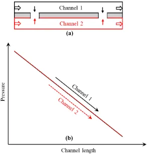
3.3Counter Flow Mini-Channel Heat Sinks
In counter flow mini-channel heat sink, coolant flow in the opposite direction
through two adjacent channels. Figure 3.3 (a) shows the top view of the two counter flow
mini-channels separated by a solid wall where through channel 1, coolant is flowing from
(a)
Figure 3.3 (a) Top view of counter flow channels along with flow directions, (b) local pressure distribution along the channel length (figure is not drawn to scale).
left to right and coolant is flowing from right to left direction through channel 2. Therefore,
for channel 1, pressure magnitude reduces linearly from left to right (inlet to outlet) as
shown in Figure 3.3 (b). On the contrary, for channel 2, pressure magnitude reduces
linearly from right to left. Apart from that, two opposite pressure profile intersects at the
middle point of the heat sinks. These two opposite pressure distributions in the adjacent
channels provide significant local pressure gradient between two channels except the
intersecting point. Positive pressure gradient is evident from channel 1 to channel 2 in the
left side of the middle intersecting point whereas, negative pressure gradient is evident in
the right side as shown in Figure 3.3 (b). Therefore, by utilizing this pressure difference
in-(a)
between two adjacent counter flow channels, secondary flow can be generated by
incorporating inter-connectors.
Figure 3.4 (a) Top view of inter-connected counter flow channels along with flow direction, (b) local pressure distribution along the channel length and secondary flow
directions (figure is not drawn to scale).
In order to create secondary flow, two inter-connectors were employed in the
middle solid wall. It is worth mentioning that positive pressure gradient from channel 1 to
2 across the left inter-connector results in some secondary flow from channel 1 to 2 as
shown in Figure 3.4 (a) and (b). Similarly, positive pressure gradient from channel 2 to 1
across the right inter-connector results in some secondary flow from channel 2 to 1. This
secondary flow breakup the thermal and hydraulic boundary layers and eventually enhance
the overall performance of the channel heat sinks compared to the conventional
mini-channel heat sinks.
(a)


![Figure 2.1 Passive heat transfer enhancement techniques [30].](https://thumb-us.123doks.com/thumbv2/123dok_us/8347988.1382148/35.612.98.518.278.577/figure-passive-heat-transfer-enhancement-techniques.webp)
![Figure 2.2 Knurled micro-channel heat sink [34].](https://thumb-us.123doks.com/thumbv2/123dok_us/8347988.1382148/36.612.214.406.359.539/figure-knurled-micro-channel-heat-sink.webp)
![Figure 2.3 Micro-channel with Y-shaped bifurcation [39].](https://thumb-us.123doks.com/thumbv2/123dok_us/8347988.1382148/38.612.181.424.217.434/figure-micro-channel-with-y-shaped-bifurcation.webp)
![Figure 2.10 Micro-channel heat sink with transverse micro-channel (all dimensions are in mm) [31]](https://thumb-us.123doks.com/thumbv2/123dok_us/8347988.1382148/48.612.104.508.67.404/figure-micro-channel-heat-transverse-micro-channel-dimensions.webp)