Article
Oil Droplet Clouds Suspended in the Sea. Can they
be Remotely Detected?
Zbigniew Otremba
Department of Physics at Faculty of Marine Engineering, Gdynia Maritime University, Morska Street 81-87, 81-225 Gdynia, Poland; [email protected]
Abstract: Oil floating on the sea surface can be detected by both passive and active methods using the ultraviolet-to-microwave spectrum, whereas oil immersed below the sea surface can signal its presence only in visible light. This paper presents an optical model of a sea area deeply polluted by an oil suspension (10 ppm) located in a layer (thickness 5 m) separated from the sea surface by a clear layer (thickness 1 m). The impact of wavelength and state of the sea surface on reflectance changes is shown based on the results of Monte Carlo ray tracing. A two-wavelength index of reflectance is proposed to detect oil suspended in the water column (645-469 nm).
Keywords: oil; seawater; suspension; detection; radiance reflectance
Introduction
Various satellite and air techniques are currently used to detect and trace oil spills [1,2] including optical methods. When viewed using optical methods, oil on the sea surface manifests itself clearly through the modification of reflective features and transparency of the water-air interface as well as the distribution of wave slopes, whereas oil floating below the sea surface (e.g. after using dispersants) can manifest its presence to an observer (or receiver) located above the sea surface (aircraft, satellite) only in the visible range of the electromagnetic wave spectrum. In order for such a possibility to occur, oil must affect the solar photons penetrating the water column, furthermore, the impact of oil substances on light must differ from the similar impact of water together with its natural constituents (dissolved and suspended).
An above-water remote-sensing-reflectance (Rsr) meter [3,4] would be a useful device to detect oil through observation of changes in a light stream coming from the water column. Therefore, according to the definition of the Rsr (1), the model for detection of "clouds" of oil droplets suspended in the sea described in this paper refers to the vertical reflected radiance (Lr) formed under the defined incident above water solar vector irradiance (Ei).
=
(1)
where:
– reflected radiance (the vertical-to-sea-surface flux of radiant energy per unit of solid angle / unit of projected surface area )
– the incident vector irradiance above the sea surface (defined further in the denominator of expression 2)
Model
The remote sensing reflectance (Rsr), as a parameter characterizing light coming from the water column, depends on the interactions of photons with water molecules, water density fluctuations and various suspended or diluted water natural constituents (or even man-made ones). These interactions find their quantitative expression in both absorption and scattering coefficients as well as in the angular distribution of scattered light, together commonly known as Inherent Optical Properties (IOPs). The probability distributions required in the Monte Carlo method are converted from the Inherent Optical Properties (IOPs) of water and from Fresnel formulas for the air-water border as well as from the surface wave slope distribution.
To a certain degree, Rsr depends on the angular distribution of above-water downward (solar) radiance which is a source of photons migrating in the water column (some of the photons are returned back into the atmosphere). From a remote-sensing point of view, a complete optical description of any area is a Bidirectional Reflectance Distribution Function (BRDF). In this case, Rsr for a specific wavelength is defined as follows:
R
sr(
,∅
) =
( ,∅ )=
,∅ , ,∅ ( ,∅
/ ) ∅
,∅
/ ∅
(2)
where:
, ∅ – direction of the reflected light
( , ∅ ) – the upward (reflected) radiance under specified direction ( , ∅) – the solar and sky downward (incident) light radiance , ∅ – direction of the incident solar light (Fig. 1)
BRDF – Bidirectional Reflectance Distribution Function
If the sea surface is observed vertically, the expression (2) is simplified to the following form (3):
R
sr= R(
= 0)=
( )=
,∅ , ( ,∅
/ ) ∅
,∅
/ ∅
(3)
BRDF is a physical quantity introduced in the 1970s [6] to characterize ground optical features. BRDF cannot be measured directly in the water environment, but it can be modeled through Monte Carlo photon tracing (although this requires IOPs as the input data). On the other hand, Rsr is possible to operationally measure by a remote-sensing--meter, i.e. an integrated device consisting of a downward plane irradiance (Ei) meter and upward radiance (Lr) meter. Prediction of Rsr for a sea polluted with oil-in-water emulsion is important because it can help in the interpretation of Rsr of a sea endangered by oil pollution. Essential elements of this interpretation include detection of oil dispersed in the water column, possible identification of the kind of oil and, most importantly, signaling that the remote sensing interpretive model (implemented for a specified area of the sea) is disturbed by the presence of oil.
There are several questions regarding the visibility of "underwater oil", for example, the impact of the floating oil depth, the concentration of oil, the distribution of the size of oil droplets, the type of oil (its optical properties) and the thickness of oiled water layer. Other questions include: the role of wavelength, solar radiance angular distribution, IOPs of seawater and the degree of sea surface undulations.
conditions shown in Figure 2, the IOPs of seawater in Figure 3 and the IOPs of an oil suspension in the "oil cloud" in Figure 4. The model of solar light condition assumes some of the light coming directly from the sun (Esun) at a defined angle and part evenly from the whole sky (Esky). The problem is similar to that described by Mobley et al. [8] who analyzed the impact of the seabed on the above-water upward radiance. IOPs of water were estimated from MODIS remote sensing reflectance as a result of the SeaDAS processing software [9] and IOPs of oil droplet suspensions were derived by Mie theory [10,11] using Romashkino-type crude oil optical parameters [12,13,14]. The fact that the model takes into account strictly defined characteristics, constitutes its limitation to extend results to other weather and lighting conditions as well as optical properties of oil and inherent optical properties of the seawater.
Fig. 1. Schematic system of a sea environment polluted with an oil cloud (index w relates to clean water, o – water polluted with oil, β – volume scattering function)
Fig. 3. Two components of IOPs of the seawater applied in the model: absorption coefficient aw and scattering coefficient bw. The third component of IOPs – Volume Scattering Function is used after Petzold [15]
Fig. 4. Two components of IOPs of the oil droplet suspension for 10 ppm applied in the model: absorption coefficient ao and scattering coefficient bo. The third component of IOPs – the Volume Scattering Function – is used according to Otremba et al. [7].
In the Monte Carlo simulation of the light transfer in an aquatic environment, the destinations
of 2 billion virtual solar photons falling on the sea surface have been tracked. Photons returning vertically to the atmosphere were counted in the narrow conical sector (apex angle 8o – which means
that the recorded radiance value was averaged in a solid angle of 0.0157 sr). Simulation of light propagation in the water environment using a traditional PC to achieve the accuracy of this study
may take several weeks.
Results and discussion
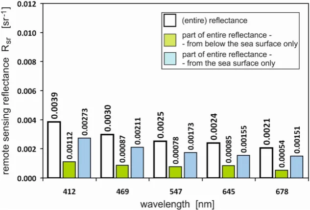
Fig. 5. Reflectance of the sea area for various wavelengths (white bars) in the distribution of a light stream coming from a water column (green bars) and from the sea surface (blue bars).
Fig. 6 presents the results in a similar way to those presented in Fig. 5, although Fig. 6 presents a case with an oil-contaminated layer under the sea surface.
Of course, the reflectance component related to the sea surface is the same for the clean sea and a deeply-contaminated sea because the wave slope distribution and light reflection/transmission through the water-atmosphere interface are not disturbed – in contrast to when the surface is covered by an oil film. Reflectance for the polluted sea decreases with the wavelength and is less than for the clean sea.
Fig. 6. Reflectance vs. wavelength (similar to Fig. 5), but for a sea area polluted with oil (as shown in Fig. 1).
Fig. 7. Index showing how reflectance of the sea area is greater from the same area polluted by oil (white bars) in the distribution of a light stream coming from a water column (green bars) and from the sea surface (blue bars).
All of the above results relate to calm sea surfaces. If the surface is undulated, the detector also captures solar glints and the observed reflectance increases. In Fig. 8, the contrast of a polluted area in relation to a clean area for various states of the sea surface is shown. The contrast declines rapidly with the degree of the sea surface undulation (expressed by wind speed [7]), to only several m/s because over 5 m/s it appears to almost be stabilized (Fig. 9).
Fig. 9. Contrast observed by a detector above the sea surface as a function of wind speed (based on Fig. 8).
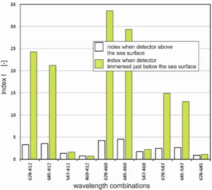
It is unclear what wavelength the sea should be observed at to detect a deeply-polluted area. In analyzing the graph in Fig. 7, it is possible that in the vicinity of 469 nm various other factors may decrease the visibility of an oil cloud in specific places. Therefore, the above-presented results were also analyzed in terms of two-wavelengths, setting the index-I representing the ratio of the reflectance at two wavelengths, as is shown in Fig. 10. The index-I was calculated according to the formulae (4).
=
(4)
where Rk, Rn – reflectance used in every combination for the five wavelengths used, numbered by n and k (k<n).
Fig. 10. Index I for combinations of each studied wavelength.
The index-I takes maximal value (4.5) at the wavelength combination 645–469 for an above-water detector and at combination 678–469 for a subsurface detector.
oil optical properties [17]. Furthermore, the applied oil droplet size distribution is typical for oil-in-water emulsion mechanically made in the seawater [18]. The oil concentration (10 ppm) applied in this study is significant, but relatively not too high (the permissible oil concentration in the vessel waste-waters cannot exceed 15 ppm).
The quantitative indeterminacy of these results in relation to possible fluctuations of IOPs of the sea water has not yet been determined. Of course, in high turbidity waters, deeply-immersed oil clouds will be invisible. On the other hand, in highly-transparent waters, oil clouds will be detectable up to a few dozen meters.
It is worth noting that the possible presence of a suspension of oil in sea water can interfere with the performance of remote sensing measurement processes in the sea (e.g. phytoplankton contents) using algorithms adjusted for pure (not oiled) sea area. It is very possible that signals indicating unnaturally high amounts of green plankton in the Gulf of Mexico reported in 2011 by Hu et al. [19] were caused by the presence of oil dispersed in the water.
It is possible that an additional factor in improving the ability to remotely detect oil in the depths of the sea is the ability of oil droplets to polarize (or depolarize) light in the scattering process [20]. It is not yet known to what extent this affects the polarization of light exiting an aquatic environment.
The research described in this paper applies to the detection capabilities of oil substances dispersed in the water column and additionally when the water surface and the oil underwater cloud are separated by a clean water layer. In situations when the water layer polluted by oil is in contact with the surface, an oil film appears. The reflective properties of the surface then change, which must be included in the optical model of the defined aquatic environment.
Other remote (but not remote sensing) methods of oil detection in the water could also be considered. They will likely include fluorometric or acoustic detectors installed on remotely-controlled underwater vehicles [21, 22].
Conclusions
Following the light field simulation in water contaminated with dispersed oil, it may be concluded that oil floating under the sea surface can be remotely sensed in the visual range of light even in low concentrations (several ppm) by measuring the radiance reflectance at two wavelengths (470 and 645 nm). However, it should be taken into account that the results presented in this paper apply to only one form of oil-in-water – namely, a dispersed oil forming an underwater cloud. Additionally, it has been confirmed that a clean water layer (about a 1 m thickness) above a polluted layer does not prevent perceiving that pollution. Other variables were not analyzed, such as the thickness of both clean and polluted water layers, oil concentration, size distribution of oil droplet suspension, IOPs of the sea water, geometry of the solar lighting and direction of the wind in relation to the plane of incidence of solar photons. Since the method used (a Monte Carlo simulation of the tracing of a large number of photons migrating in water) to predict the radiance reflectance is, unfortunately, time consuming, determination of the degree of impact of all of the above-listed factors on the effectiveness of remote detection of underwater oil pollution does not seem to be realistic. However, it is planned to conduct tests to provide information on the impact of lighting conditions (from clear sky to overclouded) on the visibility of underwater oil. In addition, if other possible suggestions appear, they can be realized in the framework of the above-described method.
Acknowledgements: This paper was supported by Gdynia Maritime University grant No. DS/411/2016.
References
1. Fingas, M., Brown, C., Review of oil spill remote sensing, Marine pollution bulletin 2014, 83(1), 9-23.
2. Liu Y., MacFadyen A., Ji Z.G., Weisberg R.H., Monitoring and Modeling the Deepwater Horizon Oil Spill: A Record-Breaking Enterprise, Geophys. Monogr. Ser. 2011, 195, 271
3. Garaba, S. P; Zielinski, O., Comparison of remote sensing reflectance from above-water and in-water measurements west of Greenland, Labrador Sea, Denmark Strait, and west of Iceland, Optics Express 2013, 21(13), 15938, doi:10.1364/OE.21.015938
4. Haule K., Freda W., Darecki M., Toczek H., Possibilities of optical remote sensing of dispersed oil in coastal waters, Estuarine, Coastal and Shelf Science 2016, in press (available online 9 August), doi:10.1016/j.ecss.2016.07.013.
5. Leathers R.A., Downes T.V., Davis C.O., Mobley C.D., Monte Carlo Radiative Transfer Simulations for Ocean Optics: A Practical Guide, Naval Research Laboratory Washington, Report No. NRL/MR/5660--04-8819, September 2004
available online: file:///C:/Users/User/Downloads/ADA426624.pdf (accessed 10 August 2016)
6. Nicodemus F.E.; Richmond J.C.; Hsia J.J.; Ginsberg I.W.; Limperis T. Geometrical Considerations and Nomenclature for Reflectance. U.S. Department of Commerce 1977. Available online:
https://graphics.stanford.edu/courses/cs448-05-winter/papers/nicodemus-brdf-nist.pdf (accessed 20 June 2016).
7. Otremba Z, Zielinski O., Hu C., Optical contrast of oil dispersed in seawater under windy conditions, Journal of the European Optics Society2013, 8, pp. 13043:1-6.
DOI: http://dx.doi.org/10.2971/jeos.2013.13043
Available online: https://www.jeos.org/index.php/jeos_rp/article/view/13051/1043 (accessed 20 June 2016).
8. Mobley C.D., Zsang H, Voss K. J. Effects of optically shallow bottoms on upwelling radiances: Bidirectional reflectance distribution function effects, Limnology and. Oceanography 2003,48, 337–345.
9. Lee Z.P., Carder K. L, Arnone R. A. Deriving inherent optical properties from water color: A multiband quasi analytical algorithm for optically deep waters, Applied Optics 2002, 41, 5755–5772. Available online:
ftp://misclab.umeoce.maine.edu/users/optics/classFTP/Readings/Lee-2002-AO.pdf (accessed
20 June 2016).
10. Bohren C.F., Huffmann D; Absorption and Scattering of Light by Small Particles, John Wiley, New York 1983, p. 233.
11. Jonasz M.; Fournier Georges; Light Scattering by Particles in Water: Theoretical and Experimental Foundations, Elsevier Academic Press 2011
12. Otremba Z., Piskozub J. , Phase functions of oil-in-water emulsions, Optica Applicata 2004, 34, 93-99. Available online: http://www.if.pwr.wroc.pl/~optappl/pdf/2004/no1/optappl_
3401p93.pdf (accessed 20 June 2016).
13. Otremba Z. Modeling the bidirectional reflectance distribution functions (BRDF) of sea areas polluted by oil, Oceanologia2004, 46, No. 4, 505-518
14. Otremba Z. Influence of oil dispersed in seawater on the bi-directional reflectance distribution function (BRDF), Optica Applicata 2005, 35, 99-109
Available online: http://www.if.pwr.wroc.pl/~optappl/pdf/2005/no1/optappl_3501p99.pdf
(accessed 20 June 2016).
15. Petzold T. J.; Volume scattering functions for selected natural waters,” SIO Ref. 72–78 Scripps
Institution of Oceanography, La Jolla, Calif., 1972
16. Cox C., Munk W. Measurements of the roughness of the sea surface from photographs of the
sun’s glitter, Journal of the Optical Society of America 1954, 44, 838–850 Available online: http://userpages.umbc.edu/~martins/phys650/Cox%20and%20Munk%20Glint%20paper.pdf
17. Otremba Z. The impact on the reflectance in VIS of a type of crude oil film floating on the water surface, Optics Express 2000 (accessed 20 Juni 2016).
https://www.osapublishing.org/oe/abstract.cfm?uri=oe-7-3-129&origin=search
18. Otremba Z., Oil droplets as light absorbents in seawater, Optics Express 2007, 15, No. 14 Available online: https://www.osapublishing.org/oe/abstract.cfm?uri=oe-15-14-8592&origin=search (accessed 20 June 2016).
19. Hu C., R.H. Weisberg Y. Liu L. Zheng K.L. Daly D.C. English Zhao J., Vargo G.A., Did the northeastern Gulf of Mexico become greener after the Deepwater Horizon oil spill?, Geophys. Res. Lett. 2011, 38, L09601, doi:10.1029/2011GL047184.
20. Otremba Z., Piskozub J., Polarized phase functions in oil-in-water emulsion, Optica Applicata 2009, (Vol.39), No.1, 129-133. Available online:
http://www.if.pwr.wroc.pl/~optappl/article.php?lp=677 (accessed 20 June 2016).
21. Detection of Oil in Water Column, Final Report: Detection Prototype Tests. United States Coast Guard, Environment and Waterways Branch, Report No. CG-D-06-14, July 2014. Available online:
http://www.bsee.gov/uploadedFiles/BSEE/Technology_and_Research/Oil_Spill_Response_R
esearch/Reports/1000-1099/1021AA.pdf (accessed 20 June 2016).
22. Ryan J. P., Zhang Y., Thomas H., Rienecker E. V., Nelson R. K., Cummings S. R., A
high-resolution survey of a deep hydrocarbon plume in the Gulf of Mexico during the 2010 Macondo blowout, in Monitoring and Modeling the Deepwater Horizon Oil Spill: A Record-Breaking Enterprise, American Geophysical Union, Washington, D. C., 2011