c. (.I
o ..:::
_
'--•
') r: o
c
,; <) o
r
.,C' 0
o
o
o
'" I
"
0-au ,ES
>- 0- v
j
'
n-o-, J
-0--0-CJ
9 <~~
. ' "
-<.>-)
. _:M~
,0
)
r 'itN, N.
( ,
C '\ f ,
0
UNIVAC~
r
o C'
I o o o o ., o o ' ) o v o o -' IJ , ) o o 0 ' o o o n o o o o J o o ") ' ) ( ) ()
.,
A UJ ('
c. o " o (J o
~. CL M 4 (
N J '
' " ) J I . . - l ? (..{) f t ()
A
v 0 V U 1) G ( l J 1 r
("\
L
8
) ) I
(.J L ( U ( l . . . : ) n ) I"l.... _ _ _ ' _ _ J _ L J _ r _ d. ...:::," _ G ... 2 () _ ~ _ rJ 1_<" « > \
-c, "16 ., Il l} l ., 4 .. I
} 0CJ ) r ' \ C f") ' t
o
c
6
10
,
and
t
12
;
0
"
~
punched-card
electronic computers
U
v
N I
V
1
A
C®
c- f. -') ~'
,
c • (
)1
•
ramming
UNIVAC® 6 0
and
UNIVAC®120
punched-card electronic computers
Index
Section I - Introduction
Section II - Machine Functions
1. Accumulator 2. Elements 3. Storage 4. Program step 5. Operational functions 6. Selectors
7. Reproduce
Section III - Programming Techniques
1. Transfer into storage 2. Accumulation 3. Rounding 4. Range testing
5. Use of an element as the result of a step 6. Testing designating information (sequence check) 7. Placing more than one value in a storage 8. Crossfooting
9. Wiring alpha into the accumulator 10. Wiring constants through input
11. Wiring a card column as an element and to pick up selectors 12. Card position sele.ction
13. Making an element zero or a significant value 14. Conversion of codes to constants
15. Overlapping card fields
16. Wiring more than one program on a panel 17. Verification
18. Card code checking
19. Accumulating positive and negative values in one storage 20. Square root
21. Obtaining a product of more than ten digits 22. Fractional twelfths
23. Program select loop 24. Punching zeros from storage 25. Techniques for conserving functions 26. Approaching a program
Section IV - Operating Instructions
1. Wiring connection panels 2. Operation
3. Testing a program
Section V - Course Outline and Sample Problems
1. Course outline 2. Sample problems
4
7
14 20 37 43 50 62 87 101 103 103
104
111 116 117 125 130 132 134 135 137 138 140 142 146 149 151 166 176 178 182 187 196 210 211
Section I Introduction
The Univac 60 and 120 are electronic computers designed to operate with 90-column punched cards. The two computers are identical,except that the Univac 120 has more input and storage capacity than the Univac 60.
The computer consists of two units - the card sensing-punching unit, and the electronic computing unit. The two units are joined together by electrical cables. Two removable connection panels govern the routine by which the punched cards will be processed. The input-output panel indicates the columns to be sensed and punched; the constant-program panel contains the program which is to be followed - that is, the series of steps through
which the computer must go to obtain the desired results. The two connection panels are both inserted in the electronic computing unit; they may be easily removed and others containing a different program inserted, or a panel may be rewired by the operator to handle another program.
The card sensing-punching unit is the portion of the computer through which the cards are fed. The sections of the sensing-punching unit through which a card passes may be diagrammed as follows:
Feeding Sensing Punching
Receiving (Sort)
Receiving (Normal)
The card is stationary both while values are being sensed in the sensing station and punched in the punching station. The full ninety columns in the card may be sensed simultaneously and used in calculation without being entered in the storage units of the computer. Information punched into the card may be either results calculated by the computer or informa-tion reproduced from the same or a preceding card.
The card sensing-punching unit operates at a maximum speed of ISO cards a minute. If, however, due to a particularly long program or one that repeats
The sensing-punching unit contains a control panel with six switches and eight lights. The switches are used for such operations as turning the computer on, starting and stopping it. The lights are indications to the operator as to the functioning of the computer.
The electronic computing unit handles the computations necessary to
com-plete a program. A program is the series of arithmetic steps through
which the computer solves a problem. The maximum number of program steps
available on the computer is 40, although this number may be effectively
increased by various programming techniques. The computer is basically a
"three address" computer - during one step two values are called upon, and the result of the operation upon them is placed in storage. The basic form of a program step. together with the symbols which will be used throughout the manual, is:
Step Number Value I
VI
Process Pr
Value 2
=
V2
=
Result
R
Branching -Br, +Br
It is the programmer's responsibility to reduce the problem to a series of steps in this form.
There are four processes available, anyone of which may be used on any of
the 40 program steps. They are the arithmetic functions of addition,
sub-traction, multiplication, and division. There are also certain operational functions used in programming, such as start, but these may not be used as the process of a step.
The values in a program step may be of three types: a card-read field, a
constant value, or the result of a previous step. Since the sensed set-up
is locked in sensing switches during the entire program for that card, any field of the card which has been wired may be called upon at any time. Constant values are wired on the constant-program panel, and are also
available at any time. Both card-read fields and constant values are
re-ferred to as elements. The maximum number of elements available on the
computer is 36. Each element may have a maximum of 10 digits plus sign.
The result of a previous step may be used as a value in any following step until the result is cleared, either by the entry of new information into the storage unit or by a clear instruction from the computer.
The result of a program step is placed in a storage unit. There are six
storages on the Univac 60, and 12 storages on the Univac 120. Each
storage contains 10 columns plus sign. When a result is placed in a
storage, it will remain there until cleared as mentioned in the preceding paragraph. The result may be used as necessary in succeeding steps
either during the program for the card which is sensed or that of any
following cards. I t may also be punched into the card which is sensed,
or any following cards.
Program stepson the computer are completely non-sequential. It is
possible to wire from one program step to any of the other steps, or to
any operational function. For example, step 5 could be wired to step
of whether the result of the step which has just been completed is plus or minus - that is, if the result of step 5 is plus the program could continue with step 6, while if it is minus it could continue with step
2. This is known as the plus or minus branching of a step.
The computation of every program step on the computer is automatically
checked before the computer continues to the next step. If it does not
check, the computer will repeat the step or the program, until the result does check, or until the cause of the failure is corrected.
Although the computer is basically a numeric computer, it is possible to reproduce both alphabetic and numeric information. The reproducing may be in the same card columns as the original information, or may be to any
other columns of the card. It may be done into the same card that is
sensed. or any following card or cardso
The computer may be used to summarize information which has been calculated and/or accumulated from the preceding cards. Designating information may be punched into the summary cards from storage units, and reproduced into the summary cards from preceding cards.
Section II
Machine Functions
1. Accumulator
A. Description of the accumulator
B. Entering card-read fields into the accumulator
C. Entering constants into the accumulator
D. Storage as related to the accumulator E. Decimal locations
F. Operation of the accumulator G. Dropping digits
H. Summary
2. Elements
A. General
A-1 Description of an element A-2 Decimal location
A-3 Sign
A-4 Use as a value B. Card-read fields
B-1 Columns of input
B-2 Assignment of element numbers B-3 Element designators
B-4 Field transfer lines B-5 Card sensing B-6 Control transfer lines B-7 Negative control B-8 Accumulator inputs B-9 Decimal locations
C. Constants
C-1 Constant digits
C-2 Wiring of constant digits C-3 Decimal locations
C-4 Assignment of element numbers D. Program charts
D-1 Table of factors D-2 Accumulator inputs D-3 Elements
E. Summary
3. Storage
A. General
A-1 Storage capacity
A-2 Use of storage as a value or result A-3 Clearing storage
A-4 Decimat\locations B. Punching from storage
B-1 Wiring for punching B-2 V-wiring of storage output
C. Program charts
D. Summary
4. Program step A. General
A-1 Sequence of program steps
A-2 Process
A-3 Value 1, value 2, and result A-4 Branching
A-5 Proof A-6 Speed B. Program charts C. Summary 5. Operational functions
A. General
A-1 Description of operational functions A-2 Wiring of operational functions A-3 Program charts
B. Start C. Trip
D. Set 1 and set 2 D-1 Purpose
D-2 Use of two set instructions D-3 Program chart
D-4 Wiring D-5 Skip control D-6 Set hold E. Sort 1 and sort 2
E-1 Purpose
E-2 Use of two sort instructions F. Clear
F-1 Purpose F-2 Use
F-3 Clearing step F-4 When to clear F-5 Program chart F-6 Wiring G. Program selects
H. N -;- 0; 0 -;- 0
H-1 Description H-2 Use
H-3 Program chart H-4 Wiring
I. Restart
J. Summary 6. Selectors
A. General B. Card control
B-1 Pick-up of selectors B-2 Wiring
B-3 Program charts
C. Program selects C-1 Purpose C-2 Internal wiring C-3 Example of use
C-4 Connection panel wiring
Section /I Machine Functions (continued)
D. Selector hold 70
D-l Purpose 70
D-2 Example of use 71
D-3 Wiring 71
D-4 Program chart 72
E. Delayed pick-up 72
F. Additional examples of the use of selectors 73
F-l Differentiating between several codes 73
F-2 Differentiating between odd and even codes 75
F-3 Pick-up of a selector by an even number 76
F-4 Wiring more than one position in a column as minus 77
F-5 Setting the same storage on both set 1 and set 2 78
F-6 Using "clear" more than once 79
F-7 Reusing steps through use of a program select 79
F-8 Changing the decimal location of storage 81
F-9 Y-wiring of accumulator input 82
F-l0 Wiring selector pick-up through constants 84
G. Summary 86
7. Reproduce 87
A. General 87
B. Card column wiring 87
C. Control of reproduce 89
C-l Reproducing into the same card 89
C-2 Reproducing into following cards 92
D. Skip control 93
E. Set hold 95
F. Secondary reproduce 97
APPLICATION:- ~ ___ ""R-uL
DIVISION, Of SPERRY lAND corpORATION
TABULATING MACHINES UNIVAC 60 &. 120
PUNCHEO-CARO ELECTRONIC COMPUTERS
10 II U \J I . . . I. 11 II 11 10 I ' I t U lot n u_u II n JO JI U U J4 n I t n II II <1O 4' 41 U U U
" ' 0
,.
o
o 0 0 0 0
• o 0 0 0 0 0 0----0---0---0
• 2
o 0
o 0
o 0
0 0 0 0 0 0 0 0 . - - - 0 - - - 0 - - - - 0
<>-<>----0---<>
BUSES
o 0 0 0 0 0 0 0 0----0---0---0
o 0 0 0 0 0 0 0 0 0 0 0 0 0 0 0 0 0--0--0--0
... 5 A 6
0 0 0 0 0 0 0 0 0 0 0 0 0 0 0 0
o 0
ACCUMULATOR INPUTS
o 0 0 0 0 0 0 0 0 0----0---0---0
o 0 0 0 0 o 0
BUSES
0 0 0 0 o 0 0 0 0 0 0 0 b 0 0----0----0--0
• • o o 0
" o
o 0
• 10
0 0 0
o 0 0 0 0 0 0 0
~ 0 0 0 0 0 0 0 0 0
CARD SENSING
0 0 0 0 0 0
" o
0 0 0 • 0
o 0 0 0 0 0 0 0 0 0 0 0 0
o .0 0 0 0
0 0 0 0 0
CARD SENSING
0 0 0 0 0 0
o 0 0 0 0 0 0 0 0
" ·1 1 1 1 1 1 I I I 1 I I I I 1 I
..
.. • 0
o "
o 0 0
. .
0 0o 0 0 0 0
FlllD
o 0 0 ! l I~
~.U~HR 0 lIlt?'
0 0 0
10 II If o
o 0 0
1l 14 11
~ 0 0
0 0 0 0 0 0 0 0 0 0 0 0 0 0
CARD PUNCHING
0 0 0 0 0 0 0
o " o 0
o
u
o
2J ~. IS . .
o 0 0 0
o " o
..
o0 0 0 0 0 0 0 0
o 0 0
.. 41 ~
o 0 0 0 0
o 0
5& ~,
o 0 0
0 0 0 0 0 0 0 0 0 0 0 0 0
CARD PUNCHING
0 0 0 0 0 0 0 0
i2 " n i6 61 U 6'1
o 0 0 0 0 0 0
O O O O O O O Q O
u •
W II! 1 1 1
rrr:tI1ItI11TIT
J I 5
4-" 0 0 0
.
o.
00 0 0 0 0 0 0 0 0 1 ) 0 0
S I S
0 0 0 0 0 0 0 0 0 0 0
..
o 0
o 0
2
o 0---0-0--<>
f - - - + - - - j BUSES
o 0---<>--<>-0
o 0 0 0 0 0 0 0 0 O~ 0 0 0--0----0--0
S 5 S 6
o 0 0 0 0 G--O----O----O
STl)flAGE OUTPUTS
O O Q O O O O O O O O O 00----0----0--0
o o o o o o o o o q
0 0 0 0 0 0 0 0 o 0 0 0 0 0 0 0----0---0--<)
S • S 10
0 0 0
"
.
0 0 0 0 0 0 0 0 0 0 0 0
0 0
"
0 0 O.0 0 0 0 0 0 0 0 0 0 0 0 0 0 0 0 0 0 0 0 0 0 0 0
0 0 0 0 0 0
0 0 0 0 0 0 0 0 0 0 0 0 0 0 0 0 0 0 0 0 0 0 0 0 0 0 0 0 0 0 0 0 0 0 0 0 0 0 0 0 0 0 " " " " " .. • 0 0 0 0 0 0 . 0 0 0 0 0 0 . 0 0 0 0 0 0 , 0 0 0 0 0 0 ' 0 0 0 0 0 0 ' 0 0 0 0 0 0 ~O 0 0 0 0 0
·1
..
1
I
1 1 1
" " " ,
• 0 0 0 0 0 0 ' 0 0 0 0 0 0 • 0 0 0 0 0 0 , 0 0 0 0 0 0 • 0 0 0 0 0 0 . 0 0 0 0 0 0 ~o 0 0 0 0 0
·1
I I I I I
:;, f~6 :;, FYI fl, :io
10
.
0 0 " o o 0 .. 0I. PUT & OUTPUT PAIEL
.
0 0 0 0 0 0 0 0 0 0 0 0 0 0 0 n 0 0 0 0 0 0 01
" 0 0 0 0 0 0 0 I R,.
,.
.
. . .
"
. .
0 0 0 0 0 0 0 0 0 0
0 0 0 0 0 0 0 0 0 0
• 3
0 0 0 0 0 0 0 0 0 0 0 0 0 0 0 0 0 0 0 0
0 0 0 0 0 0 0 0 0 0 0 0 0 0 0 0 0 0 0 0 0 0 0 0 0 0 0 0 0 0
• 7
0 0 0 0 0 0 0 0 0 0
.CCUMULATOR INPUTS
0 0 0 0 0 0 0 0 0 0 0 0 0 0 0 0 0 0 0 0 0 0 0 0 0 0 0 0
• 11
0 0 0 0 0 0 0 0 0 0 0 0 0 0 0 0 0 0 0 0 0 " » .. "
.
.
0 0 0 0 0 0 0 0 0 0 0 0 0 0 0 0 0 0 0 0 0CAItO SUSING 0 0 0 0 0 0 0 0 0 0 0 0 0 0 0 0 0 0 0 0 0 0 0 0 0 0 0 0
1 1 1 1 1 1
I
" " " ~ "
.. ..
0 0 0 0 0 0 0 0 0 0 0 0 0 0 0 0 0 0 0 0CARD SEfIIlNG 0 0 0 0 0 0 0 0 0 0 0 0 0 0 0 0 0 0 0 0 0 0 0 0 0 0 0 0
I I I I I I I
fInD TRANSflR lINU
F~F~g •. ~~f~7~
"
o
~ ~ ~
0 0 0 0 0 0 0 0 ·0 0 0 0 0 0 0 0 0 0 0 0 0 " q
" 0 0 0 0 0 0 0 0 0 0 0 0 0 0 0 0 0 0 0 0 0
I
1 1
" H
.
0 0 0 0 0 0 0 0 0 0 0 0 0 0 0 0 0 0 0 0 0
1
I1
:ft f~O ~l
.
.
.
.
. .
.
0 0 0 0 0 0 O.
0 0 0 0 0 0 O. • •
0 0 0 0 0 0 O.
0 0 0 0 0 0 O'
0 0 0 0 0 0 O'
0 0 0 0 0 0 0> 0 0 0 0 0 0 O'
• 8
0 0 0 0 0 0 O'
0 0 0 0 0 0 0 ' 0 0 0 0 0 0 O'
0 0 0 0 0 0 O·
0 0 0 0 0 0 O' • 12
0 0 0 0 0 0 O·
0 0 0 0 0 0 0 ' 0 0 o -'t_"- 0--".' "
..
" U"'"
0 0 0 0 C>--<> 0
SM.1P
0 0 0 0 C>--<> 0 SEIHOlO 0 0 0 0 C>--<> 0 0 0 0 0 <>--<>--<>
0 0 0
:j
0 0 0 0 0 0
COIIIIONS
! !
I I
..
0..
0..
0..
0 0 0 0 0 0 0 0 o I 0---<>-0 0 0°1=
0 0 0 °l~
0 0 0
°1=
0 0 0 o I
0---<>-1 0---<>-1 0---<>-1
1:::-Fe;, ,~ ,0.. ;;, ;;. f~' ,~.o
u
o 0 0 0
o
..
o
0 0 0
31 )I 40
o o 0
0 0 0
U 44 45
0 0 0
o 0 0 0 0 0 0 o 0
CARD PUNCHING
o 0 0 0 0 0 0
0 0 0 0 0
r-· I I I I I I I I I I I I I I 1 I 1 1 1 1 1 ~~, ..
10 0 0
1<1 11 n
o 0 0 0 0
o 0 0 0
" 11 11
o o 0
..
" o 0o 0 0 0 0 0
~ ~
0 0 0
o 0 0 0 0 0 0
CARD PUNCHING
0 0 0 0
S5 iii 11 U
o 0 0 0
o 0
.. ..
o 0
r-r- • r-r- ,
r-r-o 0 o. r-r ~
o 0 0 0 0 0 0 0 0 0 0 0 o 0 0 ~~ ~ 41 .-+--<
o 0 0 0 o 0 0 ~/--<
'111111 I 11.1 1111 1 111111
S OOTPUTSIGN 10
TO 0 0 0 0
OU $I 5J S4 R O O 0 0
ASS 56 51 " , G O O O O Q O E59 SlO 'II 512
0--0--0---<>
0---<>--0--<> 0
BUSES
C>-O---o----O
1 , 5 4 )
o 0 0 0 0
o 0 ' 0 0 0 0
S 3
Or, 0 0 0 0 0
0 0 0
..
oo '0 0
o 0
0 0 0 0 0 0 0
S •
o 0 0 0 0
o 0 0 0
o 0
o 0 0 0 0 0 0 0 0 0 0 0
S 7 S 8
0 0 0 0 0 0 0 0 0 0
STORAGE OUTPUTS
o 0 0 0 0 0 0 0 0 0 0 0 0 0 0 0 0 01 ., 0 0 0 0 0 0 0 0 0 0 0 0
0---<>--<>-0
0---<>--<>-0~~~~~~~~6~0~0~~~0~~0~O~O~O-O--0--~
o 0 0 0 0 0 0 0 0 0 0 0 0 0 0 0 0 0 0 OJ IS
S 11 S 12
C)-4-Q--O---Q 0 0 0 0 0 0 0 0 0 0 0 0 0 0 0 010 ..
0----<>-<>-<> 0 0 o 0 0 0 0 0 0 0 0 01 11
APPLICATION:-$T[~
b !. ~ 6 6 ~
.
6 " ""
"' D 0 0 0 0 0 0 0 0 0 0 0 0 0 0 0 0
M
-0 0 0 0 0 0 0 0 0 0 0 o 0 0 0 0 0 0 0 0 0 0 0 0
BRANCH
-I
I
I
I I I
!
I I
I 1 I 1
!
I
I I
QI
1
!
I
1
!
b
~
!
!
I
I
~BUSES
I
!
I I I I I I I
I
I I I I I I I I I
!
{fffffffffi~~~fftf1tttfi
no 0 0 0 0 0 0 0 0 0 0 0 0 0 0 0 0 0 0 0 0 0 0 0
sUP ,
.
" " " .. .. " " " " " " no 0 Q 0 0 0 0 0 0 0 0 o 0 0 0 0 0 0 0 0 0 0 0 0
EQUATION
• 0 0 0 0 0 0 0 0 0 0 0 o 0 0 0 0 0 0 0 0 0 0 0 0
, 0 0 0 0 0 0 0 0 0 0 0 0 0 0 0 0 0 0 0 0 0 0 0 0
Sl[P ,
.
.." " .. " " " .. " " " " " "
' D 0 0 0 0 0 0 0 0 0 0 0 0 0 0 0 0 0 0 0 0 0 0 0
- 0 0 0 0 0 0 0 0 0 0 0 o 0 0 0 0 0 0 0 0 0 0 0 0
PROCESS
• 0 0 0 0 0 0 0 0 0 0 0 0 0 0 0 0 0 0 0 0 0 0 0 0
'" 0 0 0 0 0 0 0 0 0 0 0 0 0 0 0 0 0 0 0 0 0 0 0
~o 0 0 0 0 0 0 0 0 0 0 0 0 0 0 0 0 0 0 0 0 0 0 0
n
"
..
n..
, 0 0 0 0 0 0 0 0 0 0 0 0 Q 0 0 0
.
0 0 0 0 0 0 0, 0 Q 0 0 0 0 0 Q 0 0 0 Q 0 0 0 0 0 0 0 0 0 0 0 0
SELECTORS
me 0 0 Q 0 0 0 Q 0 0 0 0 Q 0 0 0 0 0 0 0 0 0 0 0
m no
'" m
'"
, 0 0 0 0 Q 0 0 Q Q 0 0 0 0 0 0 0 0 0 0 0 0 0 0 0
" " " "
, 0 0 0 0 0 0 0 Q 0 0 Q 0 0 0 0 0 0 0 0 0 0 0 0 0
, , , ~
.
, ~!. 6 0 13 " 15 16 " ~ I ~ " " 0 0 "
0 0 0 0 0 0 o 0 0 0 0 0 0 0 0
CONTROL , ... NSFE. LIII[$
0 ~ 0
~ 0 0 Q 0 ~~ .. ~ Ugm~1 Pf f ~ 0 0
1~_1~ 0 0 0 0 0
, ,
. .
,.
" " "
~ ~ 0-0----<>-<>-<> ~
PtIOG,SU.1 I'ROG,SEl.11 PIIOG. S€L. III PROG.SEL.IV
0 ~ " " 0 " "
flO fll fU Rl F'H n~ 116 fl1 fl' '19 F:20 f21 0 0 0 0 0 0 o flE~ I~A"S~[R ~N{S
0 0 0 0 0 0 0 o 0 Q
1tftttfttfffftfftfftffff
ELEMENT DESIGNATORS0 0 0 0 0 0 0 0 0 0 0 o
.-
0 0 0 0 0 0 0 0 0 0 0 0, I I I I I I I
1
I
I I I
I I
I
I I I
1
I
1
!
I
!
CONSTANT DIGITS
, 0 0 0 0 0 0 0 0 0 0 o 0 0 0 0 0 0 0 0 0 0 0 0 0
0 0 0 0 0 0 0 0 0 0 0 0 0 0 0 0 0 0 0 0 0 0 0 0
, I I I I I I I I
1
! I I
CONSUNTI
DIGITSI I I I I I I I
I
!
1
0 0 0 0 0 0 0 0 0 0 0 0 0 0 0 0 0 0 0 0 0 0 0 0
0 0 0 0 0 0 0 0 0 0 0 0 0 0 0 0 0 0 0 0 0 0 0 0
,1
I I I I I I I
! ! !
1 1
I I I I I I I I I
!
I
CONSTANT OIGtTS
0 0 0 0 0 0 0 0 0 0 0 0 0 0 0 0 0 0 0 0 0 0 0 0
0 0 0 0 0 0 0 0 0 0 0 0 0 0 0 0 0 0 0 0 0 0 0 0
, 0---<>---<>-0 ~
~J.~ ~ 0 - < > - 0 - - 0
,~ 0-<>--<>-<> ~~ ~o--c ~
""""""!'
<mo".~ ~ 0-<>--<>-<> o-p-<>-<> 0-<>-<>---<> ~
10 0 8 7 • 5
,~ 0-<>--<>-<> 0-<>--<>-<> 0-<>--<>-<> 0-<>-<>---<> ~ .~ 0-<>--<>-<> <>-<>--0-<>' 0-<>-<>---<> 0---0-<>-<> 0--0--<>--0
0--0--<>--0 <>-0---<>-0 0--0--<>--0 ~ 0-<>-<>---<> 0--0--<>--0 0--0--<>--0 ~ » - 0 - < > - 0 0--0-<>-<> 0-<>-<>---<> ~
»--<>-<>--<> 0--0--<>--0 ~ 0--0--<>--0 0---0-<>-<> ~
BUSES
»--<>-<>--<> ~ <>-<>--0-<> ~~ ~ »--<>-<>--<> 0---<>--<>-<> 0--0--<>--0 ~ ~ 0--0--<>--0 ~
0 0 0 0 0 0 0 0 0 0 0 0 0 0 0 0 0 0 0 0 0 0 0 0
0 0 0 0 0 0 0 0 0 0 0 0 0 0 0 0 0 0 0 0 0 0 0 0
0 0 0 0 0 0 0 0 0 0 0 0 0 0 0 0 0 0 0 0 0 0 0 0
0 0 0 0 0 0 0 0 0 0 0 0 0 0 0 0 0 0 0 0 0 0 0 0
0 0 0 0 0 0 0 0 0 0 0 0 0 0 0 0 0 0 0 0 0 0 0 0
0 0 0 0 0 0 0 0 0 0 0 0 0 0 0 0 0 0 0 0 0 0 0 0
0 0 0 0 0 0 0 0 0 0 0 0 0 0 0 0 0 0 0 0 0 0 0 0
0 0 0 0 0 0 0 0 0 0 0 0 0 0 0 0 0 0 0 0 0 0 0 ,
" ' 0 0 0 0 0 0 0 00'
- 0 0 0 0 0 0 0
· I I
!
I I
1 1
!
I I I I I
0
0
~"&uuL
DIVISION Of sPERRY I1ANO eOHORATION
TABULATING MACHINES UN IVAC 60 &. 120
PUNCHED-CARD ELECTRONIC COMPUTERS
CONSTANT & PROGRAI PANEL
" 0 0 0 0 " 0 ~ 0 0 oS 0 o~ 0 DIS CIS ~OOOl
0 0 0 0 0 0 0 0 0= 0 0= 0 0'" 0< o~ 0'"
9R ~ Ne H
1 1 1 1
I I I I I
0!s 0 :~:
o~ 0!S On OOUT:;;
0 - 0 0 - 0:;; ol:i 0 IN
BUSES
I I
f
I I I I I
!
I I I I
I
?i
¢6
fftffffftf~~1~ffffffffft
.. 0 0 0 0 0 0 0 0 0 0 0 0 0 0 0 0 , 0
0 ' ? 0----0 STE'
" " " "
..
" " n n ...
".
" RESTART" 0 0 0 0 0 0 0 0 0 0 0 0 0 0 0 0 , 0
ST;~t o 0
EQU,o,TION .n " ~
' 0 0 0 0 0 0 0 o 0 0 0 0 0 0 0 0 ' 0
o.
!
'0=0
,+0 • 0 0 0 0 0 0 0 0 0 0 0 0 0 0 0 0 • 0 0>0 o 0
SUP
" " " "
..
" " n"
..
..
" ~ "..
~s;-+0 0 0 0 0 0 0 0 0 0 0 0 0 0 0 ' 0 0"
0+0
- 0 0 0 0 0 0 0 o 0 0 0 0 0 0 0 0 • 0 0 " 0 0
PROCESS "' $1'111
."
SUII T(>PSOII]• 0 0 0 0 0 0 0 0 0 0 0 0 0 0 0 0 0 0 0 0 0
~~ SKIP
+0 0 0 0 0 0 0 0 0 0 0 0 0 0 0 0 0 0 0 0 0 o 0 0
" 0 0 0 0 0 0 0 0 0 0 0 0 0 0 0 0 0 0 0 0 0 0 0 0
'" '" .n .n ."
, 0 0 0 0 0 0 0 0 0 0 0 0 0 0 0 0 0 0 0 0 0 0 0 0
" " " ,.
, 0 0 0 0 0 0 0 0 0 0 0 o 0 0 0 0 0 0 0 0 0 0 0 0
SELECTORS
",0 0 0 0 0 0 0 0 0 0 0 0 0 0 0 0 0 0 0 0 0 0 0 0
m m
'" ". ..,
, 0 0 0 0 0 0 0 0 0 0 0 0 0 0 0 0 0 0 0 0 0 0 0 0
, 0 0 0 0 0 0 0 0 0 0 0 0 0 0 0 0 0 0 0 0 0 0 0 0
" " " n '
"
.. ..
0 ~16~2 u .,
..
..
0 0 ~ I ~ 0 0 0 0 0 0 0 0 0 0 0 0 0,,& 0 0 0
0 0 L CT ~ PICk 0 0 0 0 ~j~ 0 0 0 0 0 0 0 o 0 0
~!~ o 0 0 g " 32 11
"
..
".
..
~ M..
"
..
" 511). 51! '"~I_~~
rn fl6 f21 n. rtf flO >3) f32
'"
.•
f35 fK rl1.•
...
... '4~ f'6 ...0
o 0 0 0 FoE3, T~ANS~[R ,?NU 0 0 o 0 0 0 0 0 0 0 0 o 0 0 0
~ ;: "'
,i, 'I" ,1" 'i-
.~..
~..
~. ,~, 'g'·t·
.g.,I" .:,
0 0 0 0 0 0 0 0 0.,
.-
." ." .n0 0 0 0 0 0 0 0 0 0 0
ELEMENT DESIGNATORS Nn N2S
.,
.. ..
...
.
,...
0 0 0 0 0 o 0 0 0 0 0 0 o 0 0 0 o 0 0 0 0 0 0 0
", .. us OECIMU lOCATORS
, I 1 I
I ! I I I
1 1 1
I
0 0 0 0 0 0 0 0 0 0 0 0n
" ~ M
"
..
"..
" n.'" '" CONSTANt DIGITS
: I
1 .. 1 . 1
:JJ
'1:1:
r '
1 ' 1 ' :
0 0 0 0 0 0 6 0 0 0 0 0
0 0 0 0 0 0 0 0 0 0 0 0
I
f
I I
~
, 1
I
r
I
1
I
I
I
I
I
I I
CONSTANT DIGITS
t
0 0 0 0 o 0 0 0 0 0 0 0
BUStS
~ ¢
0 0 0 0 0 0 0 0 0 0 0 0
!
t
, I I
I I
I 1
I
1
I I ! !
~ 6t
t
? ,CONSUNT OIGITS
0 0 0 0 0 0 0 0 0 0 0 0
T 9
0 0 0 0 0 0 0 0 0 0 0 0 b 6 0 6
,~
~J.~ ~ 0 0 0 0 0 0 0 0
,~ <>-0---<>-0 ~ ~ 0 0 0 0 0 0 0 0
"CU"'''':"!
<0""".~ , ~~ ~ 0 0 0 0 0 0 0 0
3 2 1
,~ <>-0---<>-0 ~ ~ 0 0 0 0 0 0 0 ,
.~ ~~ 0--0-<>-<> 0 0 0 0 0 0 0 0
~ <>-0---<>-0 0--0---<>-<> ~ 0 0 0 0 0 0 0 0
~ <>-0---<>-0 0--0---<>-<> ~ 0 0 0 0 0 0 0 0
~ <>-0---<>-0 0--0-<>-<> ~ 0 0 0 0 0 0 0 0
BUSES
»-<>---0--0 0-<>--<>-<> ~ ~ 0 0 0 0 0 0 0 0
0----<>--<>---< ~ <>-0--0--0 <>--0--<>-<> 0 0 0 0 0 0 0 0
0 0 0 0 0 0 0 0 0 0 0 0 0 0 0 0 0 0 0 0 0 0 0 0
0 0 0 0 0 0 0 0 0 0 0 0 0 0 0 0 0 0 0 0 0 0 0 0
0 0 0 0 0 0 0 0 0 0 0 0 0 0 0 0 0 0 0 0 0 0 0 0
0 0 0 0 0 0 0 0 0 0 0 0 0 0 0 0 0 0 0 0 0 0 0 0
0 0 0 0 0 0 0 0 0 0 0 0 0 0 0 0 0 0 0 0 0 0 0 0
0 0 0 0 0 0 0 0 0 0 0 0 0 0 0 0 0 0 0 0 0 0 0 0
0 0 0 0 0 0 0 0 0 0 0 0 0 0 0 0 0 0 0 0 0 0 0 0
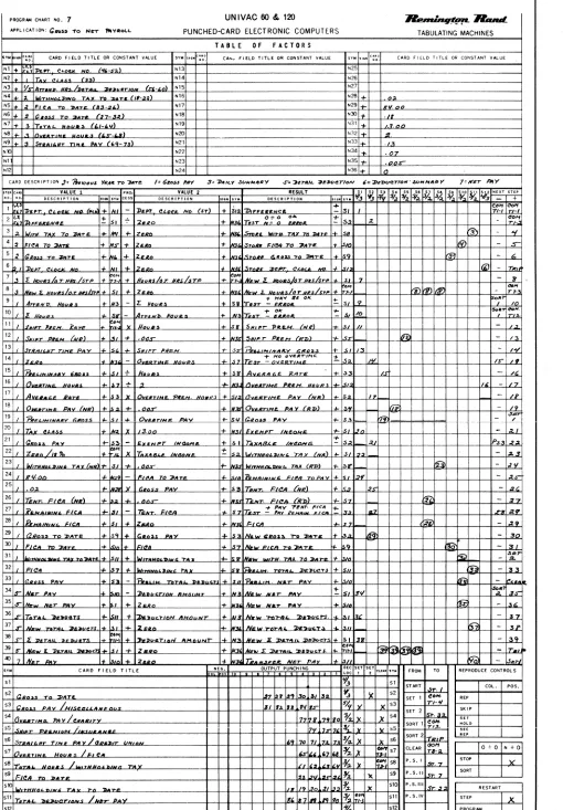
PROGRAM CHART NO. UNIVAC 60 &. 120 ~R-d. APPLJ CAT ION: PUNCHED-CARD ELECTRONIC COMPUTERS
TABULATING MACHINES TABLE OF FACTORS
,.
••• c~~~ CARD FIELD T I TL E OR CONSTANT VALUE ". II'. ~~I> • CARD FIELD TITLE OR CONSTANT VALUE".
". c •• o ". CARD FIELD TITLE OR ,CONSTANT VALUENl N13 N25
N2 N14 N26
N3 N15 N27
N4
"'" N28
N5 NI7 N29
N6 N18 N30
N7 N19 N31
N8 N20 N32
N9 N21 N33
NIO N22 N34
Nl N23 N35
N12 N24 N36
CARD DESCRIPTION
STr:~ ,,~ VALUE 1 PRO- VALUE 2 RESULT
" s. s. s.
" S. 57 so
" S10 SI1 '12
~rT-"" . "". OESCRIP'TION ". "" CESS DESCRIPTION ".IY. DESCRIPTIO .. ." ".
1
2 3 4 5 6 7 8 9 10 11 12 13 14 15 16 17 18 19 20 21 22 23 24
25
.
26 27 28
29
30 31 32 33 34 35 36 37
38
39
of:)
".
CARD FIELD TITLE NEG. OUTPUT PUNCH I NG DEC SET SETtU"AR no FROM TO REPRODUCE CONTROLS
Loo I
.
51 51 ST M.T COL. POS.
52 52
SET 1 REP
53 53
SET 2 SKIP
54 54 SET
SORT 1 NOl.O
55 55 SEC
SORT 2
...
56 56
57 57 CLEAR 0+0 N + 0
58 58 P.5. I STOP
SELECTOR CHART NO.:
APPLICATION!
(CNUMT ,ACTOR', CARD FACTO . . .
EUII
TO NEG.CONT. OE
,.S .. COL 'OS n. LO
I.' •• Nl N2 N3 N4 N5 N6 N7 N8 09 Nl0 oIl 012 N13 N14 015 N16 017 N18
UNIVAC 60 &. 120
PUNCHED-CARD ELECTRONIC COMPUTERS ELEMENTS
'NOICAn DECIMAL LOCATION. NEGATIYE CONTROL AIID VALUE IN DUIItED .CCU ... LATOR COLU ...
INDICATE TIIANSH. LINE {FULD.,., '1. £TC. CONTROL. CI. CI. IT1;.1 DECIMAL LOCATION. NEeATIVE CONTROL AND TRANSFER liNE. INDICATE CAitO COLUMNS IN ACClIIULATOit I .. PUTS ON RIGHT.
ACCUMULATOR COLUMNS ELEM. NEG.CONT. OEC ACClM.JLATED COLU,..S TO
10 9 8 7 6 5 4 3 2 1 DES 16
COL '0 T,": LOC 10 9 8 7 6 5 4 3 N19
c N20
N21 N22 N23 N24 N25 N26 N27 N28 029 N30 N31 032 N33 N34 N35 N36
R E P R 0 0 U C E
~&uuL
TABULATING MACHINES ACCUMULATOR INPUTS
TO' LINE. TItAII'FU LINE (PI,FI. lTC., INDICATEI
10TTOIII LINE. CAItO COLUMNS
ACClM.ILATED COLUMNS OW.
2 1 10 9 8 7 6 5 4 3 2 .1 .2 .3 .4 .5 .6 A7 AS AS Al0 .11 A12
FROM COLUMN I I I I I I I I I I I I I I I 1.1 I I I I I I I I I I III I I I I I 1.1 I I I I II I I I II I I I I I
TO· COLUMN I I 1/ I I I I I I I I I I I I I I I I I I I I I I I I I I I I I I I II I I I I I I I I I I I I I I I CONTROL I I I I I I I I I I I I I I I I I I I I I I I I I I_LLLLLllili i
SELECTOR CONTROL CHART
'N.OlS. IUECTOR • • f l . ' , fl."Z, TI.S, TI.". T2, ETC. ULleT • • • SEl. VALUE 1 • • • VI n£MENTS • . . NI. N2. NS. ETe.
COMMON • COM IUHCM • ; • alt: VALUE I • • • VI STORA8[ • • • Sf. St. S3. ETC. NON SELECT. • N.S. PROCESS • • PR. RESULT • • • ItES. PROGRAM SELECTOR • • • P.S.I. P.S.2. [TC. SELEC TR'. PICK UP
NON. SELECT SEL' l'RFIt
PICI( UP
SELECT C"",",O NON·SELECT TOR . LIME a:::n: ::rA~o~:: SELECT COfMON TOR LINE pot! TIOII .. NO COLUMN
III Ic ... Tr L ... yCONT
~ ~
~ j-!.:J
~ 11.4 ~ 1.4
12 2
.g:2 F:l
~ 13.3 ~
~
~ 3.4
14 4
~ ~
15-2
t;t.i 's:3
~ ts.4
16 6
.!Z.:.! ~
.!!..:1 g
!l;] ~
17.4 7.4
18 8
~
E=-!-.!2:.! ~
.!!:1 ~
19.4 9·4
~ 21.1
t:2
~
;:;
~ 31.4 t:4
32· 22
~ ~
~ 23-2
ffi
~ 33.4 ~
34 24
~ ~
~ ~
~ 35. ~
25.4
36 26
~ ~
~ ~
~ 37. ~ 27.
1.
Accumulator
A. DESCRIPTION OF THE ACCUMULATOR
Before discussing the features of the computer from a programming view-point it is well to have an understanding of the accumulator. The
accumulator is a group of~electronic tubes in which all computation occurs. It may be thought of as having 22 -columns, as follows:
M Section
Available for values and results
Each column is made up of the necessary electronic tubes to create any numeric digit from 0 to 9.
Although all 22 columns may be used during calculation, value I and value 2 of a program step must be placed in the accumulator in columns 10-1 of the A section. When the result of a step is placed in storage, no significant digit may be located in column II of the A section. If this happens, the computer will "hang up", stopping on the step in which this occurs. However, it is possible to drop off any number of digits to the right of column I of the A section without hanging up the computer. These digits will be placed in the M section, beginning in the 11th column. The use of the M section and column II of the A section during computation is automatic with the computer, and need not concern the programmer. It is his responsibility, however, to be certain that no result being placed in storage could have a significant digit in column II of the A section.
Paragraphs Band C below explain how card-read fields and constants enter columns 10-1 of the accumulator~ Paragraph 0 explains the relation of storage to the accumulator.
B. ENTERING CARD-READ FIELDS INTO THE ACCUMULATOR
-
, ,.
.
,.
. .
, ,. .
..
"
.
.
.
, ".
.
,
.
, , , 10 I • 7 I I 4 3 2 10 , • 7 , , • 3 l 1·
. 0 0 0 0 0 0 0 0 0 0 0 0 0 0----<>--<>-<> o 0 0 Q 0 0 0 0 0 0 0 0 0 o 0 0 0 0 0 0 0 0 01 I, ' 0 0 0 0 0 0 0 0 0 0 0 0 0 0 0 0 0 0 0 0 0----<>--<>-<> o 0 0 0 0 0 0 0 0 0 0 0 0 0 0 0 0 0 0 cO 0 0 0 OJ r
• 1 • 2 A 3 A 4
, ' 0 0 0 0 0 0 0 0 0 0 0 0 0 0 0 0 0 0 0 0 0 - 0 - - 0 - 0 o 0 0 0 0 0 0 0 0 0 0 0 0 0 0 0 0 0 0 0 0 0 0 05 J
·
. 0 0 0 0 0 0 0 0 0 0 0 0 0 0 0 0 0 0 0 0 0----<>--<>-<> o 0 0 0 0 0 0 0 0 0 0 0 0 0 0 0 0 0 0 0 0 0 0 01 •BUSES
·
. 0 0 0 0 0 0 0 0 0 0 0 0 0 0 0 0 0 0 0 0 0 - 0 - - 0 - 0 o 0 0 0 0 0 0 0 0 0 0 0 0 0 0 0 0 0 0 0 0 0 0 O' s·
.0 0 0 0 0 0 0 0 0 0 0 0 0 0 0 0 0 0 0 0 0 - 0 - - 0 - 0 o 0 0 0 0 0 0 0 0 0 0 0 0 0 0 0 0 0 0 0 0 0 0 01 ,·
. 0 0 0 0 0 0 0 0 0 0 0 0 0 0 0 0 0 0 0 0 0 - 0 - - 0 - 0 o 0 0 0 0 0 0 0 0 0 0 0 0 0 0 0 0 0 0 0 0 0 0 0 ' ,• • • 6 A 7 A , 8
0 0 0 0 0 0 0 0 0 0 0 0 0 0 0 0 0 0 0 0----<>--<>-<> o 0 0 0 0 0 0 0 0 0 0 0 0 0 0 0 0 0 0 0 0 0 0 05 •
ACCUMULATOR INPUTS ACCUIIIUI:ATOIil ,INPUTS
·
' 0 0 0 0 0 0 0 0 0 0 0 0 0 0 0 0 0 0 0 0 0 - 0 - - 0 - 0 o 0 0 0 0 0 0 0 0 0 0 0 0 0 0 0 0 0 0 0 0 0 0 01 ," ' 0 0 0 0 0 0 0 0 0 0 0 0 0 0 0 0 0 0 0 0 0 - 0 - - 0 - 0 o 0 0 0 0 0 0 0 0 0 0 0 0 0 0 0 0 0 0 0 0 0 0 0 ' 10
" ' 0 0 0 0 0 0 0 0 0 0 0 0 0 0 0 0 0 0 0 0 0 - 0 - - 0 - 0 o 0 a 0 0 0 0 0 0 0 0 0 0 0 0 0 0 0 0 0 0 0 0 01 II IUSU
" ' 0 0 0 0 0 0 0 0 0 0 0 0 0 0 0 0 0 0 0 0 0 - 0 - - 0 - 0 o 0 0 0 0 0 0 0 0 0 0 0 0 0 0 0 0 0 0 0 0 <> 0 OJ 12
• 9 • I. A 11 A 12
" . 0 0 0 0 0 0 0 0 0 0 0 0 0 0 0 0 0 0 0 0 0 - 0 - - 0 - 0 o 0 0 0 0 0 0 0 0 0 0 0 0 0 0 0 0 0 0 0 0 0 0 os u
..
' 0 0 0 <> 0 0 0 0 0 0 0 0 0 0 0 0 0 0 0 0 0 - 0 - - 0 - 0 o 0 0 0 0 0 0 0 0 0 0 0 0 0 0 0 0 0 0 0 0 0 0 01 14 0 0 0 0 0 0 0 0 0 0 0 0 0 0 0 0 0 0 0 0 - - 0 - - 0 - 0 o 0 0 0 0 0 O. a 0 0 0 0 0 0 0 0 0 0 0 0 n n n n, ISWithin each accumulator input are 10 columns of 5 positions each. The
column numbers 10-1 correspond to the 10 available columns of the accumulator, while the 5 positions refer to numeric values entering the accumulator
columns, coded in the 90-column punching code. Accumulator inputs are the means of wiring card-read fields into the accumulator so that they may be
used as values in program steps.
Column 1 of all 12 accumulator inputs is wired to column 1 of the accumulator; column 2 of all 12 is wired to column 2 of the accumulator and so forth. In actuality, the five positions in an accumulator input column are connected to the accumulator column through a decoding section, which changes the punched code into a code compatible with the accumulator. The accumulator inputs are all diode protected, which means that there is no danger of a backfeed - for example, calling on all card columns wired into accumulator column 1 when only that wired through column 1 of A2 is desired. The diagram on page 16 indicates the internal wiring of all 12 accumulator inputs to the accumulator.
All card fields to be used as values in accumulator through accumulator inputs. wiring, see page 27.
a program must be wired to the For a complete explanation of this
C. ENTERING CONSTANTS INTO THE ACCUMULATOR
ACC!UMVA.llrO It
10 • • 7 , • • , 2 1 10 • • 7 • • 4
10 0 0 0 0 0 0 0 0 0 0 0 0 0 0 0 0
' 0 0 0 0 0 0 0 0 0 0 0 0 0 {) 0 0 0
A A 12
' 0 0 0 0 0 0 0 0 0 0 0 0 0 0 0 0 0
10 0 0 0 0 0 0 0 0 0 0 0 0 0 0 0 0
. 0 0 0 0 0 0 0 0 0 0 0 0 0 0 0 0 0
...
0-2
0 , 0 0 0 0 0 0 0 0 0
S
• 0 0 0 0 0 0 0 0 0 10 0 0 0 0 0 0 0 0
• 0 0 0 0 0 0 0 0 0
•
0
0
0
0
0
1 0
0
0
0
0
2
0
0
0
0
0 1
01
0 '
O'
01
O'
"-
"-.5,. .. ~",~ It
....
" "-~.,
.
.... ...
.
.
....
" 10
•
0 0
0 0
0 0
0 0
0 0
(!OA,.V1!4 N:J
~ ...
...
"-'
...
,
• 7 , 0 0 0
0 0 0
S
0 0 0
0 0 0
0 0 0
"-•
0
0
0
0
0
..
. 4: ..
,
,
"-" 'T",
,
• 20 0 0 01
0 0 0 0 '
12
0 0 0 O'
0 0 0 07
~
" , <>---<>--¢----< <>--0-0--0
<>--0-0--0
J
<>--0-0--0<>--0-0--0 <>--0-0--0 , <>---<>---<>--0
~
1
<>--0-0--0 ~" • <>--0-0--0 <>--0-0--0 <>-<>--<>--0 <>--0-0--0 0---<>-0---<> <>--0-0--0 • 0---<>-<>--<> 0----<>----<>-0 <>---<>---<>--0
"
ACCUMULATOR COLUMNS 'CCU.ULATJ COLU •• ,
==l
' <>---<>--¢----< <>--0-0--0 <>--0-0--0 0---<>-<>--<> 0---<>-<>--<> <>--0-0--0 , <>---<>--¢----< 0----<>----<>-0 0---<>-<>--<>
10 • 8 7 6 5 4 3 2
" ,~ 0---<>-<>--<> 1
<>-<>--<>--0 I 0---<>-<>--<> <>-<>--<>--0 <>--0-0--0 , <>--<>-0--0 0----<>----<>-0 0---<>-<>--<> ~
" ,~ 0----<>----<>-0 ~I 0---<>-<>--<> <>-<>--<>--0 < > - - 0 - 0 - - 0 , <>--0-0--0 ~ <>--0-0--0 ~
-Since it is possible that a particular digital value, "5" for example, might be used in the same accumulator column as part of more than one constant
value, there are four hubs available for each position within each accumulator column. All twenty hubs within an accumulator column are wired to the corres-ponding accumulator column - that is, all twenty hubs in accumulator column 1 are wired to accumulator column 1. A backfeed does not occur because the
constant digits from which the accumulator columns are wired are neon-protected. The diagram on page 16 indicates the internal wiring of the constant accumulator columns to accumulator columns.
A complete explanation of constants is found on page 31.
D. STORAGE AS RELATED TO THE ACCUMULATOR
Storage as related to the accumulator differs from card-read fields and constant values. A number is not only called upon to enter the accumulator from storage to be used as value 1 or value 2 of a program step, but the
results of program steps are taken from the accumulator and placed in storage.
Each storage unit has 10 columns, numbered 10-1. As indicated in the diagram on page 16, column 1 of each storage unit is internally wired to column 1 of the accumulator, column 2 of each storage unit is wired to column 2 of the accumulator, and so forth.
As explained below, the programmer has control over the accumulator columns in which a value from storage will be placed through assignment of a decimal location to each storage. No wiring of storage columns to the accumulator is ever done by the programmer - this is all internal wiring. The only wiring of storage columns with which the programmer is concerned is that of storage outputs to punching columns in the card. This is covered on page 39.
E. DECIMAL LOCATIONS
except as it may be altered through use of selectors. If the decimal
location is not wired, the computer will hang up on the first step in which the element or storage is called upon.
Decimal locations are assigned with reference to the accumulator. For example,
assume that a five-digit price, punched in card columns 30-34, is to be entered
into accumulator columns 5-1 of accumulato.r input 1. The decimal point in
the card falls between columns 32 and 33. It would be placed as follows:
Accumulator columns (AI)
Card columns
In this case the decimal point falls between Price therefore has a 3/2 decimal location. decimal locations as related to elements and and 38.
F. OPERATION OF THE ACCUMULATOR
accumulator columns 3 and 2. A complete explanation of
storage is found on pages 29
As an example of how the accumulator operates, assume that it is to add
50837 (VI) and 28Q 906 (V2). The result is to have only 2 places following
the decimal. VI and V2 are in accumulator inputs as follows:
Accumulator columns: 10 9 8 7 6 5
VI: 5 8 3
V2: 2
4 3 2 7 8 9 0
1
6
Decimal location 7/6
4/3
Before VI is called upon, the accumulator and the result storage are cleared. VI then is entered into the accumulator according to its decimal location.
The V2 decimal location is entered, and VI is shifted so that the decimals of VI and V2 are aligned.
V2 is then entered. and added to VI.
The decimal of the result storage is entered, and the result is shifted so that the two decimals are aligned.
M Section
Available for values and results
Referring to the above diagram notice that there is a connection between
column 11 of the A section and column 1 of the M section. There is also
a connection between column 11 of the M section and c~lumn 1 of the A
section. As a value is shifted to align with a decimal location, it
always moves to the left. If both VI and V2 have the same decimal
loca-tion, value 1 shifts entirely around the 22 columns of the accumulator to align itself with the decimal location of value 2.
Assume that VI has a 3/2 decimal location and V2 has a 1/0 decimal
location. When VI aligns with the decimal location of V2, it shifts 20
places to the left so that its decimal location aligns with the 1/0
decimal location of V2. The last two digjts of VI are therefore in columns
11 and 10 of the M section. If the result is to be placed in a 3/2 storage.
the result is shifted two places to the left. The digits which were in
columns 11 and 10 of the M section will move to columns 2 and 1 of the A
section, and therefore be available. If the result is placed in a 2/1
storage, the result shifts one place to the left, bringing one digit into
column 1 of the A section and leaving one digit in colwnn 11 of the M
section. This last digit is not placed in storage, and is thereby dropped off.
If a" decimal location is not assigned to an element or a storage unit the computer hangs up, since it is searching for a decimal position with which to align and cannot find one.
Faster operation is obtained from the computer if the decimal location of V2 is different from the decimal location of VI and the result.
G. DROPPING DIGITS
As mentioned on page 14, ~ result may never have a significant digit in
column II of the A section, or the computer will hang up. However. it is
possible to compute an answer of more than 10 digits. For example, when
multiplying a 7-digit value times a 6-digit value, a 13-digit answer may be the result. The result of multiplying 843.0925 times 761.124 is 641697.
Accumulator Columns
M Section
11 10 9 8 7 6 5 4 3 2 1 11 10
7 0 0 6
9 7
o
06 4 1 6
A Section
9 8 7 6 5
4 1 6 9 7
6 4 1 6 9
9 7 9 3 5 4 3
9 3
7 9 9 7
2 1
5 9
3 5
0 0
Storage decimal location of result 5/4 .
4/3
8/7 - computer hangs up
As can be seen, by dropping off digits to the right when placing the result in storage, the answer can be adj usted so that the computer will not hang up. The digits which are dropped off are actually computed, but are lost when the
result is stored.
H. SUMMARY
1) The accumulator has 22 columns, of which the last 10 are available to the programmer.
2) Accumulator inputs for card-read fields, accumulator columns for constant digits, and storages are all internally wired to the last 10 columns of the acc umulator.
3) A decimal location must be assigned to every card-read field, constant
value, and storage used during a program. This is done with reference t6 the
accumulator columns. If it is not done, the computer will hang up.
4) A result of more than 10 digits may be computed, though only 10 may be stored. Excess digits above the limit of 10 may be dropped off to the right, but not to the left. The computer will hang up if a result which has a significant digit in column 11 of the A section is placed in storage.
2. Elements
A. GENERAL
A-I Description of an element
An element is either a card-read field or a constant which is used as a value
in a program step. The maximum number of elements available on the 60 or 120
is 36. For convenience, they are referred to in programming as Nl, N2v .••
N36. Each element may contain a maximum of 10 digits plus sign, due to the
A-2 Decimal location
As mentioned in the section on the accumulator, every element which is used
must have a decimal location, even though the element is a whole number. The
constant value of zero must a.lso have a decimal location. Without one, the
machine will hang up on the first step in which the element is called upon.
A-3 Sign
Any element with the exception of zero may be always plus, always minus, or either plus or minus dependent upon a control hole punched in the card or
a determination made during the program. Zero is always plus. An element
will always be considered plus by the computer unless it is wired to be
minus. If an element is always to be minus. this may be wired on the
constant-program panel with no need for control wiring from the card.
A-4 Use as a value
An element may be either VI or V2 of a program step. In fact, the same
element may be both VI and V2 i f desired. Since the sensed information is
locked in the sensing switches throughout a program, a card-read element
may be called upon as often as necessary during a program. In effect,
therefore, there are 90 columns of input storage. Constant elements, which are wired on the constant-program panel, may also be called upon whenever needed.
B. CARD-READ FIELDS
B-1 Columns of input
The Univac 60 may have a maximum of 60 columns of information wired as card-read input, while the 120 may have 120 columns of card-card-read input. The input columns may be divided among the elements as required by the applica-tion - on oneapplicat ion element NI might contain two columns, while on
another it mi~ht contain eight.
The number of input columns in each element is determined by the size of the
card field which is wired to the element. In general each card column will
require one column of input, though i f the card field has over-capacity
punching an additional column of input is needed. Since each card column is
wired to input by individual positions, other types of special wiring are possible which would cause a variation between card columns and input columns. An example of this is wiring alpha into the accumulator, page 132.
B-2 Assignment of element numbers
In ass igning element numbers to card fields, it makes no difference which
field is assigned to which element. Card fields usually begin with element
In a multiple card routine (for example, a payroll application where several cards are required to compute one man's pay), the same card columns may have different titles in different card forms. Columns 50-53 might be "hours today" in a daily summary card and "total hours" in an attendance card; columns 71-75 might be "gross pay" in a daily summary card, and "deduction amount" in a deduction card. In cases like this, only one element number
is assigned, since the element number refers to the card columns wired rather than the description of the field.
B-3 Element deSignators
Throughout a program, whenever a particular card field is required, the columns within -that field are called upon by the element number to which they have been wired. For example, suppose that columns 20-23, "rate", are wired as element N2; and columns 50-52, "hours", are wired as element N3. On step 5 of the program, hours are to be multiplied by rate. The program step would be:
Step 5
VI
N3 (hours)
Pr
x
V2
N2 (rate)
=
=
Sl (labor) RAlthough three columns are in the hours field and four columns in the rate field, only one wire on the constant-program panel is required to calIon each field at the proper time, rather than a wire for each column or for each position.
This is accomplished as follows:
On the constant-program panel are hubs called "element designators" (lines 36-37, A-D. There is a pair of interconnected hubs for each element.
"
ttttttfttttttttttttttttt
"g' "g'"I" "I"
"g' "go .g. "g' "g't
"g' "g' ?" [lEMENT DESIGNATORS ELEMENT DESIGNATORS
>
..
0 0 0 0"
0 0 0 0 0 0 o 0 0 0 0 0 0 0 0 0 0 0 0 0 0 0 0 0O"'NUSO 0 0 0 0 0
MINUS
When an element is called upon to be used as a value, the corresponding element designator hubs emit power. The power is transferred to the input-output panel to energize the card columns associated with the element which has been called upon. This is done through fi-eld transfer lines or "F-lines".
B-4 Field transfer lines
..
" 0 : : ~ ~ : : ~ ~ ~ : ~ ~ ~ ~ ~ ~ ~ ~ : ~ ~ ~ : ~"
'b' 'b'
,r,
'b' 'b' 'b' 'b' 'b: 'b',g:",i·
-i:':i: :f:',g·
-b"'g' -r" "r"
"b"-g' -g' 'g'
'b"~
"
... ELEMENT DESIGNATORS
A pulse entering an F-line hub on the constant-program panel will come out of the corresponding F-line hub on the input-output panel. This in turn is wired to energize all of the columns which are associated with the element.
8-5 Card sensing
On the input-output panel, each card column is represented by nine hubs (lines 16-33, A-u).
-
-
-
~-.
, ,·
. .
,.
," n
" u
..
" " u
..
" " " " " " " " " " " " " " " " " " " "
..
" " "..
..
0 0 0 0 0 0 0 0 0 0 0 0 0 0 0 0 0 0 0 0 0 0 0• 0 0 0 0 0 0 0 0 0 0 0 0 0 0 0 0 0 0 0 0 0
u ' 0 0 0 0 0 0 0 0 0 0 0 0 0 0 0 0 0 0 0 0 0 0 0 0 , 0 0 0 0 0 0 0 0 0 0 0 0 0 0 0 0 0 0 0 0 0
..
' 0 0 a° 0 0 0 0 0 0 0 0 0 0 0 0 0 0 0 0 0 0 0 0 . 0 0 0 0 0 0 0 0 0 0 0 0 0 0 0
"
0 0 0 0 0..
' 0·
0 0 0 0 0 0 0CARD SENSING
0 0 0 0 0 0 0 0
.
0 0 0 0 0 0 , 0 0 0 0 0 0 0 0 0 0 0 0 0 0 0 0 0 0 0 0 o )CAItO SENSING
..
' 0 • 0 0 0 0 0.
0 0 0 0 0 0 0 0 0 0 0 0 0 0 0 0• 0 0 0 0 0 0 0 0 0 0 0 0 0 0 0 0 0 0 0 0 0 " . 0
·
0 0 0 0 0 0 0 0 0 0 0 0 0 0 0 0 0 0 0 0 0 0• 0 0 0 0 Q 0 0 0 0 0 0 0 0·, 0 0 0 0 0 0 0 0
..
" 0 0 0 0 0 0 0 0 0 0 0 0 0 0 0 0 0 0 0 0 0 0 0 0 ~o 0 0 0 0 0 0 0 0 0 0 0 0 0 0 0 0 0 0 0 0..
·1
r r r
I I
r
br
I I I I I I I I I I
r
I I I I
,I I I
r
I I I I I I I
r
I I I I I I I I I
..
..
"
.. ..
..
.
"..
..
"..
"..
.. ..
" ".. ..
..
..
..
..
..
" " " " " " " " " "..
" "..
..
..
..
"..
.. ..
"..
·
0·
" 0 0 0 0 0 0 0 0 0 0 0 0 0 0 0 0 0 0 0• 0 0 0 0 0 0 0 0 0 0 0 0 0 0 0 0 0 0 0 0 0
..
' 0 0 0 0 0 0 0 0 0 0 0 0 0 0 0 0 0 0 0 0 0 0 0 0• 0 0 0 0 0 0 0 0 0 0 0 0 0 0 0 0 0 0 0 0 0
" . 0 0 • 0 0 0 0 0 0 0 0 0 0 0 0 0 0 0 0 0 0 0 0 0 ' 0 0 0 0 0 0 0 0 0 0 0 0 0 0 0 0 0 0 0 0 0
' 0 0
cno SENSING
o >
..
0 0 0 0 0 0 0 0 0 0 0 0 0 0 0 0 0 0 0 0 0 0 , 0 0 0 0 0 0 0 0 0 0 0 0 0 0 0 0 - 0 0 0 0C .... D SEHSIN9
..
..
0. · .
0 0 0 0.
0 0 0 0 0 0 0 0 0 0 0 0 0 0• 0 0 0 0 0 0 0 0 0 0 0 0 0 0 0 0 0 0 0 0 0
..
..
0 0 0 0 0 0 0 0 0 0 0 0 0 0 0 0 0 0 0 0 0 0 0 . 0 0 0 0 0 0 0 0 0 0 0 0 0 0 0 0 0 0 0 0 b" . . 0 0 0 0 0 0 0 0 0 0 0 0 0 0 0 0 0 0 0 0 0 0 0 0 ",,0 0 0 0 0 0 0 0 0 0 0 0 0 0 0 0 0 0 0 0 0
"
,I I
r
I I
r
I
r r r
r
r
r
r r
r r
r
r
I I
r
I I
'r
I I
r r r r
I
r
I I I I
r
I
r
I I I I I
..
'" ,.. ---- ""
-, ,
.
,.
.
,.
," " " " "
..
" " " " " " " "..
" ' 0 0 0 0 0 0 0 0 0 0 0 0 0 0 0 0 0 0 0 0 0 0 0 0
" ' 0 0 0 0 0 0 0 0 0 0 0 0 0 0 0 0 0 0 0 0 0 0 0 0
" ' 0 0 0 0 0 0 0 0 0 0 0 0 0 0 0 0 0 0 0 0 0 0 0 0
" ' 0 0 0 0 0 0 0 0 0 0 0 0 0 0 0 0 0 0 0 0 0 0 0 0
CO\RO SENSING
" ' 0 0 0 0 0 0 0 0 0 0 0 0 0 0 0 0 0 0 0 0 0 0 0 0 > " . 0 0 0 0 0 0 0 0 0 0 0 0 0 0 0 0 0 0 0 0 0 0 0 0
" " 0 0 0 0 0 0 0 0 0 0 0 0 0 0 0 0 0 0 0 0 0 0 0 0
"
,I I
I I I I I I
1 1 1
r
r
I I I I I Inn I
..
..
"
..
..
..
" " "..
.. ..
"..
"..
" " ""r
..
"..
..
" , 0 0 0 0 0 0 0 0 0 0 0 0 0 0 0 0 0 0 o 0 0 0 0 0
..
' 0 0 0 0 0 0 0 0 0 0 0 0 0 0 0 0 0 0 o 0 0 0 0 0" '0 0 0 0 0 0 0 0 0 0 0 0 0 0 0 0 0 0 0 0 0 0 0 0
..
' 0 0 0 0 0 0 0 0 0 0 0 0 0 0 0 0 0 0 0 0 0 0 0 0CUD SENSING
" . 0 0 0 0 0 0 0 0 0 0 0 0 0 0 0 0 0 0 0 0 0 0 0 0
" . 0 0 0 0 0 0 0 0 0 0 0 0 0 0 0 0 0 0 0 0 0 0 0 0
" ""'0 0 0
iLn
0 0 0 0 0 0 0 0 0 0 0 0 0 0 0 0 0"
,I
I
I
I I I
I
I
I I
I
I I I I I I I
I
I
..
~ ~ : flHD T."NSF£II LINlS
..
~ ~ :: 0~ 0
F?O :;. 0 :;. :;, ,?a :? ~ R • .f?' ,~o ~I F~2 '~J F~4
" ~
...
Each card column has six sensing switches. They may be diagrammed as follows:
SE"'~IN" CARt>
.,.,.,.1'OMO ..5 .. N5'''''''
...----... I 0- - - -)- - - --O'---~~~--,I"""'--..,
I----::::-:=:::::~:::
--
t----
~:: =~-<1
1":i';,'::,J
+
..
UN . . ...j
~7-o-- - - - -"- - - ~- - - _
J
r----~-O- __ - - - ..,. __ - - - - _~ _ _ _ _ _ _ _ +-_-Io __ -..I
.r = ' - - O - o 1..---9",-0
L - -_ _
--=e---i}f __
-< ______ _
When a position is punched in a card column, the corresponding sensing switch closes. For example, i f a 4 were punched in the above column, the 3 and 9 switches would close. All closed sensing switches will remain closed until the trip signal is given. Whenever the element is called upon, ,power will flow from the element designator to the F-line, through the F-line to the common of the column, and out the corresponding positions which are punched. These in turn are wired by the programmer to the desired accumulator input
(see page 27.) From the accumulator input the pulses are sent through the decoding section to the accumulator.
..
Among the functions of the decoding section is an alpha check. If any combin-ation of punching other than a numeric code enters the decoding section, the computer will stop and the "Input check" light will light on the front of the
made, a field which is wired may have alpha punched; if the field is not called on during the program for that particular card, the computer will not stop. This is of significance when certain card columns are used in computa-tion during a detail card routine, yet in preceding heading cards the same card columns are punched with alpha. Note also that certain alpha
combin-ations such as
°
and 7 will not stop the computer, but will read as a 7.There are no zeros in the accumulator inputs, and in this case the remaining punching is correct numeric punching.
When zero is not being used, the zero common is not wired. There is no way
of wiring zero as such into the accumulator. When zero is part of a value,
as in $2.00 for example. the computer treats the absence of a significant digit as zero; therefore unless zero is being used as over-capacity or some other type of special wiring, it makes no difference whether or not it is punched.
B-6 Control transfer lines
Identical in circuitry to the F-lines are control transfer lines, or C-lines. In fact, the two may be used interchangeably if necessary. There are 48 C-lines,
numbered from Cl to C53. omitting CIO, C20, C30, C40, and C50. On the
input-output panel they are located in line 35, and on the constant-program panel in line 32. They are usually used to transfer a control position from one panel to the other.
F'ElD TRANSfER lIMB
I
0 0 0 0 0 0 0 0 0 0 0 0 0 0 0 0 0
~ flO ~I fl1 nl n. n~ rn n1 ~ FI9 ~o "1 ~ m ~ Fn 0 0 0 0 0 0 0 0 0 0 0 0 0 0 0 0 0 0 0 0 0 0 0 0 1 . F26 121 f28 129 FlO 1.31 F32 133 FI(
""" "'""" """
FlS F31 Fl7 FJ.8 Fn 140 141 FU F43 fU 1(5 "6 FH F(8I
o 0
F2 F3 o F~ 0 f~
9111 I. II I(
"
..
" ~ I 6 " " " " " " " ~I~ " " " " 31 38 ~I ~ " "
..
.. ..
"..
~I ~ " "a C'7,"TR~l ~RAN~HR 0 LINES 0 0 0 0 0 0 0 0 0 0 0 0 0 0 o 0 0 ltH~S 0 0 0 0 0 0 0 "
-' 0 , 0 0 0 0 0 0 0 0 0
" " " " " " "
0 0 0 0 0 0 0 0 0 0 0 0 0 0
0 0 0 0 0 0 0 0 0 0 0 0 0 0 0 o a 0 a 0 0
ARO PUNC!iJ!lG
a 0 a a 0
I--~~-+--I-~~--+-+ SELECTORS -+-+-~~-t-+-~~---j
, ; o 0
o , 0
; o 0
o 0
~ PROG. SEl. I
m
0 0 0 0 0 0 0
o a 0 a
PRQG. SEL. II
o 0 " o 0
PROG. SEL IV
CONTROL TRANSFER
' 0 0 0 0 0 0 0 0 0 0 0 0 0 0 0 0 0 0 " " " " " " " " " " " " " " " "
..
..
; 0 0 0 0 0 0 0 0 0 0 0 0 0 0 0 0 0 0 0 00 0 0 0 0 0 0 0 0 0 0 0 0 0 0 0 0 0 0 0 0 o 0 0 0 0 0 0 0 0
CARD PUNCHING
o 0 0
f--~~-+--I-~~--+-+ SEL£CTORS
o 0 0 0
m o 0 no 0 0 o 0 0
0 0 O O C O O O 0 0
n M ~
0 0 0 0 0 0 0 o a o 0 0 0
The control positions may be used for negative control, selector pick-up, or anyone of several other purposes.
B-7 Negative control
In line 38, A-I of the constant-program panel are the hubs for making an
element negative. Although not shown as such, any hub will actually serve
r-(--(--<
o 0 l1'" 2l
no
equally well for making any element negative.
H
tttttttttttttttttttttttt
'g' -g'
'r"
-i'
'g'
"to+
-r"
"I" "1, "1,+
" ElEMENT OESIGNATORS
'0
ElEMENT OfSIGI/,ATORS
" 0 0 0 0 0 0 0 0 0 0 0
O.'NI,IS° 0 0 0 0 0
0 0 0 0 0 0 0 0 0 0
°1l'NUSO
0 0 0 0 0
If an element is to be negative at all times, the only wiring necessary is to connect the element designator to the "minus" hub beneath it. Whenever a pulse is emitted from the element designator, the power will flow not only through the F-line to the card columns involved, but also into the ''minus'' hub9
The columns will therefore be read