R E S E A R C H A R T I C L E
Open Access
A deblocking algorithm based on color
psychology for display quality enhancement
Chia-Hung Yeh
*, Wen-Yu Tseng and Kai-Lin Huang
Abstract
This article proposes a post-processing deblocking filter to reduce blocking effects. The proposed algorithm detects blocking effects by fusing the results of Sobel edge detector and wavelet-based edge detector. The filtering stage provides four filter modes to eliminate blocking effects at different color regions according to human color vision and color psychology analysis. Experimental results show that the proposed algorithm has better subjective and objective qualities for H.264/AVC reconstructed videos when compared to several existing methods.
Keywords:Deblocking filter, Blocking artifacts, Human color vision, Color psychology
Introduction
Many video coding techniques have been developed for various kinds of applications, including multimedia com-munication, videophone, videoconferencing, video stream-ing, and high-definition television [1-4]. The goal of video coding techniques is to reduce transmission bitrates and storage data while maintaining a certain quality. The Joint Video Team (JVT) of ISO/IEC MPEG and ITU-T VCEG (Video Coding Experts Group) has developed a new standard for video coding. In December 2001, VCEG and MPEG (Moving Picture Experts Group) formed a JVT to finalize the draft of new coding standard for formal approval submission as H.264/AVC [5] in March 2003. H.264/AVC provides several enhancements to improve coding efficiency.
The discrete cosine transform (DCT) and motion esti-mation efficiently reduce spatial and temporal redundan-cies in most video coding standard. H.264/AVC divides an image into 4 × 4 or 8 × 8 block of pixels, and trans-forming each block from the spatial domain to the fre-quency domain by DCT. At low bit-rate coding, there may be only one DC and few AC coefficients to re-present an image block. Hence, coarse quantization of transform coefficients cause noticeable discontinuities at block boundaries called blocking artifacts. In other words, blocking effects are the grid noise along block boundaries in a relatively homogeneous region.
Several previous studies [6-10] have been proposed for the design of deblocking filters, which can largely be categorized into three groups. The first group uses a low pass filter around block boundaries to remove blocking artifacts [6,7]. The second group applies maximum a posterior probability technique to eliminate blocking artifacts [8]. The third group uses the set-theoretic re-construction method, which defines constraint sets by using observed data or a prior knowledge of the solution [9,10]. The intersection of all constraint sets gives the feasible set. All samples outside the feasible set are il-legal and the projection onto convex sets [11] technique is used to project them to be legal. The success of set-theoretic method depends on the constraint sets highly. In [12], the classification algorithm classifies a block into three types: PLANE, EDGE, and TEXTURE, according to statistical characteristic of an image in the pixel do-main. Each of these types has its corresponding filter to remove blocking artifacts. Similar to that in [12], the study in [13] classifies block type in the transform do-main and proposes a wavelet-based block analysis. In [14,15], some characteristics in human visual system are utilized to detect blocking artifacts; the appropriate filter is used to remove these artifacts.
In order to eliminate blocking effects, many deblocking filter algorithms have been proposed to provide nice solu-tions in still images [16-18]. The low-pass filter is also employed to eliminate blocking artifacts in video com-pression standards [19]. Tai et al. [20] proposed a deblock-ing algorithm based on five filterdeblock-ing modes by considerdeblock-ing * Correspondence:[email protected]
Department of Electrical Engineering, National Sun Yat-sen University, Kaohsiung 804, Taiwan
the activity across block boundaries. These five filtering modes include three frequency-related modes (the smooth mode, the intermediate mode, and the complex mode), one special mode, and a refined mode. Tai et al. [21] pro-posed a new method to remove blocking artifacts in the low bit-rate block-based video coding in H.264/AVC and MPEG-4. However, it is necessary to modify the filtered block size in order to suit different codecs. Then, Chen and her coauthors [22] proposed a general method which is suitable for various video compression stan-dards. Nevertheless, when edges cross block boundaries, Chen’s method may blur real edge.
H.264/AVC in-loop filter performs simple operations to detect and analyze artifacts on coded blocking boun-daries and attenuates those by applying a selected filter [23]. The H.264/AVC loop filter is an adaptive filter. The amount of filtering performed each position of the block edge depends on some factors. The filter can be divided into three levels: slice level, block level, and pixel level. The filter strength, i.e., the amount of filtering is com-puted based on the help of parameter boundary strength (BS), depending on the current quantizer, the macro-block type, the motion vector, gradient of the image samples across the blocking boundary, and other para-meters. However, the filtering algorithm is highly com-plex and is account for 33% of the total decode time in the study of the baseline profile decoder [24].
This article proposes a deblocking filtering algorithm that eliminates the blocking artifacts from H.264/AVC encoded videos. The preliminary results are published in [25]. The theoretic analysis and experiments of this article are more solid. In the detection process, the pro-posed“Sobel-Wavelet”method can clearly reveal the po-sitions of artifacts, and the proposed filter eliminates blocking effects in RGB domain, instead of YCbCr do-main, considering the effects of human color vision and color psychology. In objective evaluation, the PSNR of the proposed method is approximated to the H.264/ AVC loop filter. The proposed method has better per-formance in GBIM than H.264/AVC loop filter and other existing methods. In subjective evaluation, our proposed method has significant improvement when compared to other existing methods. Our method is also close to the H.264/AVC loop filter. In conclusion, the proposed method has the advantage of the post-processing-based method in terms of simplify and flexibility, but the per-formance is very close to H.264/AVC.
The rest of this article is organized as follows. Section
“Blocking artifacts detection”describes the proposed bloc-king artifacts detection. Then, the proposed deblocbloc-king algorithm is explained in Section “Deblocking artifact al-gorithm”. Experimental results are shown in Section“ Ex-perimental results” in order to evaluate the performance of the proposed scheme. Finally, concluding remarks and some future work are given.
Blocking artifacts detection
Because most blocking artifacts occur at 4 × 4 or 8 × 8 block boundaries in H.264/AVC encoded video, the fil-tering should focus on pixels around these block boun-daries. If filtering modifies all block boundaries, it will blur images. Hence, it is important to detect blocking Figure 1Flowchart of blocking artifacts detection.
Figure 2Sobel edge detector.
Vertical boundary
Horizontal boundary
Sh1
Sh2 Sh3 Sh4 Sv1
Sv2
Sv3
Sv4
boundaries and exclude real edges to avoid over-smoo-thing image textures and keep objective quality. The pro-posed blocking artifacts detection is based on Sobel edge detector and wavelet-based edge detector. According to our observation and analysis, Sobel edge detector detects all strong and coherent edges including real edges and blocking boundaries. Under noise condition, Sobel detec-tor may fail to detect the real edges of an image. Wavelet-based edge detection has better detection especially in noise conditions, while Sobel equally detects both block-ing artifacts and real edges. Combinblock-ing the results of Sobel and Wavelet detectors together, the proposed “Sobel– Wavelet” method can clearly reveal artifacts among real edges avoid over-smoothing problem. Figure 1 illustrates the flowchart of our proposed detection scheme.
Sobel edge detector
Sobel edge detector is a well-known tool of edge detec-tion in image processing. 3 × 3 Sobel operator acts lo-cally on an image and only detects edges at small scales. The Sobel edge detector is sensitive to high frequency; hence, Sobel can detect textures in an image. In general, Sobel edge detector uses two 3 × 3 kernels,H and V, to detect horizontal and vertical edges shown in Figure 2.
Two directional edge maps, horizontal and vertical edge information, can be determined by Equations (1) and (2), respectively.
Sh¼HF; Sh:horizontal edge map; ð1Þ
Sv¼VF; Sv:vertical edge map; ð2Þ
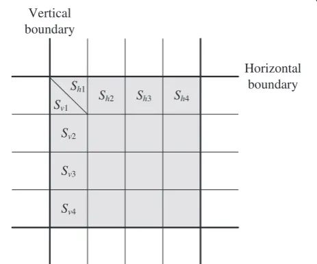
where F is an image with the size M×N, and * means convolution operation. When four values Sh1, Sh2, Sh3, and Sh4 are all greater than zero, these pixels belong to edges. And the same situation applies to Sv1, Sv2, Sv3, and Sv4. Otherwise, they just belong to textures in an image. Figure 3 illustrates the positions of four conti-nuous pixels on the vertical and horizontal block boun-daries. The decision function is given as
shð4mþi;4nÞ ¼ 1; Sh1&Sh2&Sh3&Sh4>0
0; otherwise ;0≤i<4;
ð3Þ
svð4m;4nþjÞ ¼ 1; Sv1&Sv2&Sv3&Sv4>0
0; otherwise ;0≤j<4;
ð4Þ
for 0≤m≤M=41 and 0≤n≤N=41, where Sh ¼1 and
Sv¼1 represent that the corresponding pixels belong to
edge and smooth regions, respectively. In Sobel edge de-tector, both real edges and blocking artifacts are detected and shown in the edge map. In Figure 4, the black lines in-dicate all strong and coherent edges detected by Sobel edge detector. In Figure 5, we can see that the black line indi-cates the original horizontal direction edge of the image. Figure 4Results of edge detection by Sobel operator for the first frame of TableTennis by H.264/AVC at 140 kbps. (a)Vertical direction.
(b)Horizontal direction.
Proposed wavelet-based edge detector
The proposed algorithm uses the well-known wavelet basis, Haar wavelet [26]. In the one-dimensional case, the Haar wavelet’s mother wavelet function ψð Þt can be represented as
ψð Þ ¼t
1;
1; 0;
0≤t≤1=2 1=2≤t≤1 otherwise
;
8 <
: ð5Þ
and its scaling functionϕð Þt can be defined as
ϕð Þt 1; 0≤t<1
0; otherwise:
ð6Þ
Two-scale wavelet decomposition with mother wavelet function ψð Þt and scaling functions ϕð Þt generates four coefficients, WH
1 , W2H, W3H, and W4H. The positions of these four coefficients are shown in Figure 6. According to Equations (7) and (8), four wavelet coefficients are used to generate Equations (9) and (10). The blocking effects in an image have horizontal and vertical direc-tional discontinuities. By multi-resolution analysis, cross-scale wavelet coefficients, which refers to the wavelet coefficients that have different scales but have the same orientation information such as WH
1 andW2H, are employed to generate two directional maps as
EH ¼W1HW2H; ð7Þ
EV ¼W1VW2V; ð8Þ
Next, two thresholds, Th1 and Th2, the average edge strengths in horizontal and vertical directions of one frame are used for generating edge maps in Equations (11) and (12). If EHðm;nÞ is equal to or greater than Th
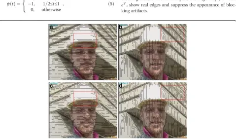
1, eHðm;nÞbelongs to an edge pixel; otherwise it belongs to blocking artifact one. In this part, the edge maps, eH and
eV, show real edges and suppress the appearance of bloc-king artifacts.
1
H
W
2
H
W
1
V
W
2
V
W
Figure 6Illustration of wavelet coefficient positions ofWH1,WH2,
WV
1, andWV2.
eHðm;nÞ ¼ 1; if EHðm;nÞ≥Th1 0; otherwise ;
ð9Þ
eVðm;nÞ ¼ 1; if E
Vðm;nÞ≥Th
2 0; otherwise ;
ð10Þ
Th1¼ 4
M∗N X
M 41
m¼0
X
N1 n¼0
Fð4m;nÞ Fð4m1;nÞ
j j
8 < :
9 =
;;
ð11Þ
Th2¼ 4
M∗N X
M1
m¼0
XN
41
n¼0
F mð ; 4nÞ F mð ; 4n1Þ
j j
8 < :
9 =
;:
ð12Þ
Sobel-wavelet detector
The proposed “Sobel–Wavelet” scheme combines the detected results of Sobel edge detector and Wavelet-based edge detector through the following equations:
Lhðm;nÞ ¼Shðm;nÞ eHðm;nÞ; ð13Þ
Lvðm;nÞ ¼Svðm;nÞ eVðm;nÞ: ð14Þ
If the pixel belongs both to the edge in the Sobel set and the true edge in the wavelet set, this pixel is deter-mined as true edge. Lhðm;nÞ ¼0 and Lvðm;nÞ ¼0
mean that F mð ;nÞ belongs to true edge in horizontal and vertical directions, respectively. Figure 7a,b shows Figure 8Details of the red region of Figure 7. (a)Sh, (b)Sv, (c)Lh, (d)Lv.
edge maps Sh and Sv. The black lines in Figure 7c,d
shows blocking effects. These two figures show blocking artifacts obtained by jointly considering the detected results of Wavelet-based edge detector that has high probability to exclude true edges. Figure 8 is the details of the red region of Figure 7.
Deblocking artifact algorithm
Our proposed blocking artifacts detection has high pro-bability to find blocking boundaries and exclude real edges compared to the conventional schemes. In this section, a new deblocking filter is proposed to eliminate blocking artifacts detected by the proposed “Sobel– Wavelet” scheme. Blocking artifacts exists both in lumi-nance and chromilumi-nance components; however, most of the conventional schemes only focus on luminance for deblocking process. Not only in luminance, the study in [19] removes the blocking artifacts both in luminance and chrominance components and obtains better results. The proposed algorithm removes blocking artifacts in the RGB domain instead of YCbCr; therefore, it can
simultaneously eliminate blocking artifacts from two com-ponents. This is because three components of filtering RGB have effect on both luma and chrominance compo-nents of the YCbCr domain. Figure 9 presents the detailed flowchart of the proposed deblocking filter based on the above concept.
Some features from human vision [27] and color psy-chology [28] are used to design the proper filter to eli-minate blocking effects. Four modes including complex mode, R mode, G mode, and B mode are used in our filte-ring stage. If the pixels belong to inverse colors across blocking boundary, this case is the complex mode. Note that inverse color is those on the opposite sides of the color wheel shown in Figure 10 [29]. Otherwise, the pixel’s
a
b
c
d
e
f
Figure 11Locations of pixels“a”–“f”in the blocking boundary.
a b c d e f b c d e
b c d e
b c d e
c d
c d
& 128
c d
R R <
& 128
c d
G G <
& 128
c d
B B <
Figure 12Position of the pixels in R mode.
c d
b c d e
b c d e c d
& 128
c d
R R <
& 128
c d
G G <
& 128
c d
B B <
a f
b c d e
b c d e
Figure 13Position of the pixels in G mode.
c d
b c d e
& 128
c d
R R <
& 128
c d
G G <
& 128
c d
B B <
b c d e
c d
b c d e
a f b c d e
major color, which has the largest amplitude among R, G, and B components, is used to determine which mode it belongs to. For example, if the pixel’s major color is R component, we deem this case as R mode.
Complex mode
The complex mode is shown in Equation (15). According to color psychology analysis, the pixels
Table 1 Parameters setting in JM 12.3
Parameter Setting
Resolution CIF
Frame rate 30 Hz
Number of frames 100
Encoder configuration Profile : high
MV search range: ±16 pixels
Sequence type: IPPP. . .
RDO: enabled
Block type: all used
Number of reference frame: 5
Frame skip: 0
Hadamard transform: used
Entropy coding method: CABAC
Figure 15Deblocking results of Foreman encoded by H.264 (CIF, Frame #1, target bit-rate: 105 kbps). (a)The original frame,
(b)non-filtered frame,(c)filtered by Tai’s [18] 4 × 4 filter,(d)filtered by Chen’s [19] filter,(e)filtered by H.264/AVC loop filter [20], and(f)
filtered by the proposed algorithm.
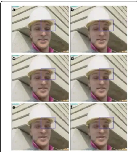
Figure 16Deblocking results of HallMonitor sequence encoded by H.264 (CIF, Frame #1, target bit-rate: 58 kbps). (a)The original frame,(b)non-filtered frame,(c)filtered by Tai’s [18] 4 × 4 filter,
(d)filtered by Chen’s [19] filter,(e)filtered by H.264/AVC loop filter [20], and(f)filtered by the proposed algorithm.
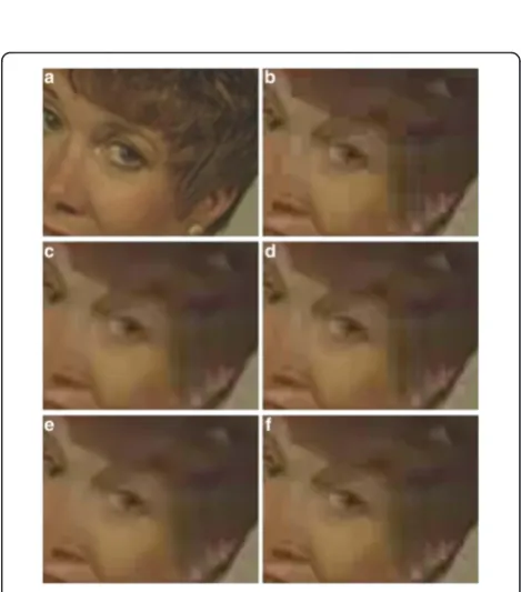
Figure 17Deblocking results of Mother&Daughter encoded by H.264 (CIF, Frame #1, target bit-rate: 36 kbps). (a)The original frame,(b)non-filtered frame,(c)filtered by Tai’s [18] 4 × 4 filter,(d)
Figure 18Deblocking results of TableTennis encoded by H.264 (CIF, Frame #1, target bit-rate: 140 kbps). (a)The original frame,
(b)non-filtered frame,(c)filtered by Tai’s [18] 4 × 4 filter,(d)filtered by Chen’s [19] filter,(e)filtered by H.264/AVC loop filter [20], and(f)
filtered by the proposed algorithm.
Figure 19Details of the blue region in Foreman (CIF, Frame #1, target bit-rate: 105 kbps). (a)The original frame,(b)non-filtered frame,(c)filtered by Tai’s [18] 4 × 4 filter,(d)filtered by Chen’s [19] filter,(e)filtered by H.264/AVC loop filter [20], and(f)filtered by the proposed algorithm.
Figure 20Details of the blue region in HallMonitor (CIF, Frame #1, target bit-rate: 58 kbps). (a)The original frame,(b)non-filtered frame,(c)filtered by Tai’s [18] 4 × 4 filter,(d)filtered by Chen’s [19] filter,(e)filtered by H.264/AVC loop filter [20], and(f)filtered by the proposed algorithm.
Figure 21Details of the blue region in Mother&Daughter (CIF, Frame #1, target bit-rate: 36 kbps). (a)The original frame,(b)
non-filtered frame,(c)filtered by Tai’s [18] 4 × 4 filter,(d)filtered by Chen’s [19] filter,(e)filtered by H.264/AVC loop filter [20], and(f)
which across blocking boundary have different funda-mental colors get more attention [28]. Hence, the proposed algorithm determines this case is the com-plex mode. Figure 11 shows the locations of the pix-els and “c” and “d” across blocking boundary. In the complex mode, the proposed filter gives different fil-ters depending on human vision system (Equation 15). Because human vision system has more attention in the complex mode, the proposed filter only update two pixels, “c” and “d” across the blocking boundary in the complex mode.
Since human beings have more sensibility on inverse colors than close colors based on color psychology, the number of updated pixels is less than other modes. In
the complex mode, the deblocking algorithm is defined as rc rd gc gd bc bd 2 6 6 6 6 6 4 3 7 7 7 7 7 5¼
1 1 32
1
32 0 0 0 0
1þ 1 32
1
32 0 0 0 0
0 0 1 1
16 1
16 0 0
0 0 1þ 1
16
1
16 0 0
0 0 0 0 11
8 1 8
0 0 0 0 1þ1
8 1 8 2 6 6 6 6 6 6 6 6 6 6 6 6 6 6 6 4 3 7 7 7 7 7 7 7 7 7 7 7 7 7 7 7 5 Rc Rd Gc Gd Bc Bd 2 6 6 6 6 6 4 3 7 7 7 7 7 5;
ð15Þ where rc, rd, gc, gd, bc, and bd are updated pixels, and
the suffixes, c and d, are the location of pixels. R, G, and B represent the pixel’s R, G and B values, re-spectively. For most parts, blocking artifacts are caused by block-based transform coding. Coding errors in block boundaries are larger than that in the interior of the block [23]. This property is a good in-dicator to design the filter. Together with the BS, dif-ferent filters are applied to each pixel position for objective and subjective quality improvement through a heuristic rule.
R, G, and B modes
Except the complex mode, we design other three modes, R, G, and B modes, according to color analysis. In the R mode, the position of the pixels is depicted in Figure 12. At the same time, we also need considering that pixel’s value in the R, G, and B components. Because this area belongs to red color, the R component needs to be filtered with more pixels. IfRc andRdare not both less than 128,
the proposed algorithm will determine that is a light color and the filter of the R component is shown Equation (16).
rb rc rd re 2 6 6 4 3 7 7 5¼
1 1 4 1 4 0 0 1 2 1 2 0 0 1 2 1 2 0 0 1 4 1 4 1 2 6 6 6 6 6 6 6 6 4 3 7 7 7 7 7 7 7 7 5 Rb Rc Rd Re 2 6 6 4 3 7 7
5; ð16Þ
Figure 22Details of the blue region in TableTennis (CIF, Frame #1, target bit-rate: 140 kbps). (a)The original frame,(b) non-filtered frame,(c)filtered by Tai’s [18] 4 × 4 filter,(d)filtered by Chen’s [19] filter,(e)filtered by H.264/AVC loop filter [20], and(f)
filtered by the proposed algorithm.
Table 2 Objective quality comparison for“Foreman”
105 k 84 k
PSNRTotal GBIM SSIM PSNRY PSNRTotal GBIM SSIM PSNRY
Non-filtering 33.32 1.15 0.84 30.61 32.31 1.18 0.82 29.41
Tai’s filter 33.27 0.92 0.85 30.54 32.32 0.92 0.82 29.44
Chen’s filter 33.38 0.96 0.85 30.68 32.38 0.97 0.82 29.50
Loop filter 33.50 0.99 0.85 30.84 32.53 0.99 0.83 29.68
IfRc andRd are both less than 128, the updated pixels
are not only four pixels but also include the adjacent two pixels as
ra
rf ¼
1 1 8 1 8 0 0 1 8 1 8 1 2 6 4 3 7 5 Ra Rc Rd Rf 2 6 6 4 3 7 7
5: ð17Þ
In the G component, the filter will update less number of pixels than the R component. If Gc and Gd are not
both less than 128, the filter is defined as
gc
gd ¼
1 2 1 2 1 2 1 2 2 6 4 3 7
5 Gc
Gd
: ð18Þ
IfGc andGd are both less than 128, the updated pixels
not only two pixels but also include the adjacent two pixels as
gb
ge ¼
1 1 4 1 4 0 0 1 4 1 4 1 2 6 4 3 7 5 Gb Gc Gd Ge 2 6 6 4 3 7 7
5: ð19Þ
The number of updated pixels in the B component and that in the G component are the same. If Bc andBd
are not both less than 128, the filter is defined as
bc
bd ¼
1 2 1 2 1 2 1 2 2 6 4 3 7
5 Bc
Bd
: ð20Þ
IfBc and Bd are both less than 128, the updated pixels
not only two pixels include the adjacent two pixels as
bb
be ¼
1 1 4 1 4 0 0 1 4 1 4 1 2 6 4 3 7 5 Bb Bc Bd Be 2 6 6 4 3 7 7
5: ð21Þ
The deblocking process of the G mode and B mode are very similar to R mode shown in Figures 13 and 14. In summary, the number of updated pixels of the certain component is more than other two components. More-over, the proposed algorithm further designs the luminance filter to avoid over-smooth the image texture for enhancing subjective quality. Here, Y is the luminance component. The designed filter is shown in the following equation:
Y¼yblockþy
2 ; ð22Þ
where yblock represents the luminance component of the image without deblocking filter, andymeans that the lumi-nance component of the image processed by the proposed deblocking filter. When the difference betweenyblock andy is greater than the predefined threshold, the filtered values are recalculated.
Experimental results
Several H.264/AVC-coded sequences, including Fore-man, HallMonitor, Mother&Daughter, and TableTennis
with different bitrates, are used in our experiments. The parameters setting in the reference software JM 12.3 high profile are shown in Table 1.
Subjective quality comparison
We compare the subjective quality of Tai’s [21] algo-rithm, Chen’s algorithm [22], and H.264/AVC loop fil-ter [23] with that of the proposed algorithm. Tai’s
Table 4 Objective quality comparison for“Mother&Daughter”
36 k 27 k
PSNRTotal GBIM SSIM PSNRY PSNRTotal GBIM SSIM PSNRY
Non-filtering 34.90 1.48 0.86 32.58 33.98 1.73 0.83 31.35
Tai’s filter 35.01 0.96 0.87 32.75 34.12 0.99 0.84 31.56
Chen’s filter 35.07 1.06 0.86 32.79 34.18 1.11 0.84 31.61
Loop filter 35.23 0.99 0.87 32.84 34.33 0.99 0.85 31.61
Proposed filter 35.08 0.71 0.86 32.73 34.19 0.75 0.84 31.53
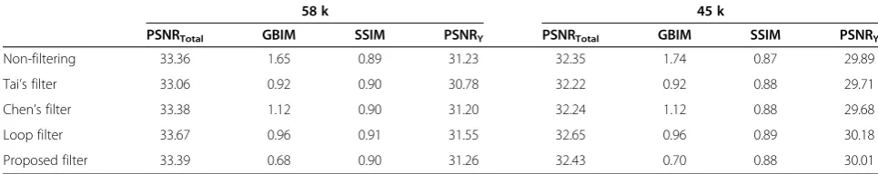
Table 3 Objective quality comparison for“HallMonitor”
58 k 45 k
PSNRTotal GBIM SSIM PSNRY PSNRTotal GBIM SSIM PSNRY
Non-filtering 33.36 1.65 0.89 31.23 32.35 1.74 0.87 29.89
Tai’s filter 33.06 0.92 0.90 30.78 32.22 0.92 0.88 29.71
Chen’s filter 33.38 1.12 0.90 31.20 32.24 1.12 0.88 29.68
Loop filter 33.67 0.96 0.91 31.55 32.65 0.96 0.89 30.18
algorithm is designed for blocking effects occurred at 8 × 8 bock boundaries, but blocking effects may occur at 4 × 4 block boundaries in H.264/AVC. Hence, this algorithm should be modified to be able to process 4 × 4 block boundaries. The mode decision step and the filter step on each mode of the algorithm are not modified in the simulation. Figures in this section show the original frame (a), non-filtered frame (b), filtered by Tai’s [21] 4 × 4 filter (c), filtered by Chen’s [22] filter (d), filtered by H.264/AVC loop filter [23] (e), and filtered by proposed filter (f ). The filtered results are shown in Figures 15, 16, 17, and 18. Furthermore, the details of the blue region of Figures 15, 16, 17, and 18 are shown in Figures 19, 20, 21, and 22. As can be seen in Figure 19c,d, Tai’s algorithm does not filter the chrominance and Chen’s method filters the chrominance, but the blocking effects still occur. In Foreman’s eyes, the proposed deblocking filter can filter blocking boundaries based on human vision system and color psychology. Our method determines that Foreman’s eyes are a complex area; therefore, this region is not over-smoothed. In Figure 20c,d, Tai’s and Chen’s methods cannot differ-entiate between blocking artifacts and true edges in an image. Hence, they may blur the true edges and decrease the subjective quality. The proposed method has the better subjective quality than Tai’s and Chen’s methods. Similar results can be seen in Figures 17, 18, 21, and 22.
Objective quality comparison
Four measurements, PSNRTotal, PSNRY, the generalized block-edge impairment metric (GBIM) [30], and struc-tural similarity index (SSIM) are used to evaluate objective quality. Here, PSNRTotal is also used in objective quality comparison due to the design of the chrominance fil-ter is considered in Chen’s method, loop filter [23], and the proposed algorithm. The function of PSNRTotal is shown as
PSNRTotal¼
4PSNRYþPSNRCbþPSNRCr
6 ; ð23Þ
In this equation, the weight of PSNRY is 4, because the sampling pattern of our tested sequences is 4:2:0. A
GBIM measures the horizontal and vertical differences, MhGBIM and MvGBIM, between the columns and rows at
all block boundaries of the reconstructed frame. GBIM is done by averaging MhGBIMand MvGBIM,
GBIM¼MhGBIMþMvGBIM
2 : ð24Þ
The major advantage of GBIM is that it calculates the blockiness of a frame without the original frame. The purpose of this measurement is to detail the state of frame blockiness. The higher the GBIM value is, the greater the severity of the blocking effects become. We also use SSIM as one of objective quality assessment metrics. SSIM is based on the study by Wang et al. [31]. The main difference of SSIM compared to PSNR is that it does not estimate perceived errors to quantify image degradations but considers them as perceived changes in structural information variation. To evaluate the debloc-king results, considering all PSNR, GBIM and SSIM seems better than only one of them.
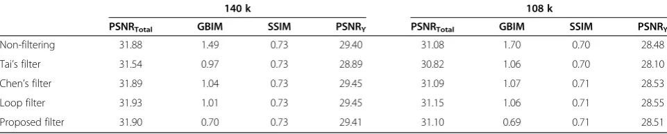
Four different sequences are used to observe their objective qualities, including Foreman, HallMonitor, Mother&Daughter, and TableTennis with 100 frames in different bitrates: 105 k and 84 k, 58 k and 45 k, 36 k and 27 k, 140 k and 108 k, respectively. The results of PSNRTotal and GBIM are shown in Tables 2, 3, and 4. The larger PSNRTotal value means the better image quality, but the GBIM value is as smaller as better. In Tables 2, 3, 4, and 5, the PSNRTotal of the proposed algorithm is higher than Tai’s algorithm by 0.03 to 0.3 dB. Because Tai’s algo-rithm does not filter the chrominance component, there are still some blocking artifacts in the Cb and Cr compo-nents. The PSNRTotal of the proposed algorithm is higher than Chen’s algorithm by 0.01 to 0.03 dB. Because Chen’s algorithm may filter true edges at block boundaries, which blurs true edges and decreases the visual quality. The proposed algorithm’s PSNRTotal is lower than that of H.264/AVC loop filter. The reason is that the H.264/
Table 5 Objective quality comparison for“TableTennis”
140 k 108 k
PSNRTotal GBIM SSIM PSNRY PSNRTotal GBIM SSIM PSNRY
Non-filtering 31.88 1.49 0.73 29.40 31.08 1.70 0.70 28.48
Tai’s filter 31.54 0.97 0.73 28.89 30.82 1.06 0.70 28.10
Chen’s filter 31.89 1.04 0.73 29.45 31.09 1.07 0.71 28.53
Loop filter 31.93 1.01 0.73 29.45 31.15 1.06 0.71 28.55
Proposed filter 31.90 0.70 0.73 29.41 31.10 0.69 0.71 28.51
Table 6 Efficiency of proposed Sobel–Wavelet detector
Real edge (%) Blocking artifact (%)
Wavelet-based edge detector 97.18 2.82
AVC loop filter uses the system information of the codec, so it can find out blocking effects more accurately than post-processing-based method. For GBIM results, the pro-posed algorithm is better than other algorithms. Especially, the GBIM of the proposed scheme is much smaller than that of H.264/AVC loop filter, Chen’s filter and Tai’s filter. This is because the proposed algorithm filtered with lumi-nance and chromilumi-nance components, and we also refineY
component to avoid over-smoothing original texture. In summary, the proposed method has better performance in terms of subjective and objective qualities when compared to other well-known methods, Chen’s filter and Tai’s filter. The proposed method has very close objective quality to H.264/AVC loop filter but the better GBIM. For SSIM and PSNRY comparisons, the H.264/AVC loop filter still has the best performance among all algorithms because it is in-loop filter and has complete coding information. In SSIM, other post-processing-based algorithms’ perfor-mances are very similar. In PSNRY, all the outcomes of our proposed method are better than that of non-filter
while some outcomes of Tai’s and Chen’s are worse than that of non-filter.
Evaluation of the proposed“Sobel–Wavelet”edge detector
Table 6 shows the efficiency of the proposed Sobel– Wavelet detector. The test frame is the first frame of Foreman sequence with the CIF resolution at 105 k bitrate. The ground truth of real edge and artifact for the test frame is determined by human directly. The de-tection results of wavelet-based edge detector for real edge and blocking artifact are 97.18 and 2.82%, respecti-vely. Wavelet-based edge detector is robust for blocking artifacts to reveal real edge. Sobel edge detector equally detects real edge and blocking artifact. The proposed Sobel–Wavelet detector can clearly reveal blocking arti-facts and detection accuracy reaches up to 99.1%.
Computational complexity comparison
The comparisons of the computational complexity and the processing time are listed in Tables 7 and 8. The
Table 7 Computational complexity comparison
ADD Shift Compare Div
Tai’s 4 × 4 filter Mode decision 12n 3n 14n –
Smooth mode 7n 12n – –
Intermediate mode 6n 4n 2n –
Complex mode 6n 6n 2n –
Steep mode 3n 4n – –
Corner mode 24n 22n 8n –
Chen’s filter Block size decision stage 26n 0.75n 0.26n 5n
No filter mode – – 2n –
Low activity mode (strong filter) 31n 20n 2n –
Low activity mode (normal filter) 16n 10n – –
Intermediate mode 9n 10n – –
High activity mode 6n 6n – –
Chrominance filter 10n 4n – –
Loop filter Strength measure 12n 8.25n 20n –
Filter type decision 6n – 6n –
Strong filter 30n 20n – –
Standard filter 11n 4n 4n –
Chrominance filter 12n 12n – –
Proposed filter Detection-Sobel 16n – 2n –
Detection-wavelate 8n 8n 2n 2n
Complex mode 9n 24n – –
R mode/G mode/B mode 9–11n 10–14n 3n –
Y filter n n n –
Table 8 Processing time comparison
CIF (100 frames) Tai’s 4 × 4 filter Chen’s filter Loop filter Proposed filter
computational operators are addition, shift, comparison, and division. Table 8 shows the processing time compar-isons of H.264/AVC encoded CIF Foreman sequence at 105 k. Experimental results show that our proposed al-gorithm has the similar complexity to the Chen’s filter [22], but higher than the Tai’s 4 × 4 filter [21]. The pro-posed algorithm filters in the RGB domain and Chen’s method filters in both Yand CbCr components, but the Tai’s 4 × 4 filter [21] just aims atYcomponent. For this reason, the computational complexity is a little higher than the Tai’s 4 × 4 filter [21], similar to Chen’s filter [22], and lower than the H.264/AVC loop filter [23].
Conclusions
This article proposes a deblocking algorithm to remove blocking artifacts for enhancement of the subjective and objective qualities of H.264/AVC encoded videos. The proposed detection algorithm differentiates between true edges and blocking artifacts to avoid over-smoothing the original texture in an image. Furthermore, the proposed deblocking filter determines the filtering stage according to color psychology analysis and gives different filters based on human vision system. As for objective quality, the proposed algorithm has higher PSNR than Tai’s and Chen’s methods; though the PSNR it is a little bit lower H.264/AVC loop filter, it has better GBIM. In subjective quality, the proposed algorithm is better than Tai’s and Chen’s methods and is close to H.264/AVC loop filter. Experimental results demonstrate the effectiveness of our proposal method. To make the proposed method more feasible, the computational complexity reduction is the major direction of our future work.
Competing interests
The authors declare that they have no competing interests.
Acknowledgements
This work was supported by the National Science Council, R.O.C, under the Grant NSC 99-2628-E-110-008-MY3.
Received: 14 May 2012 Accepted: 4 June 2012 Published: 2 July 2012
References
1. K-N Ngan, C-W Yap, K-T Tan,Video Coding for Wireless Communications
(Prentice Hall, New Jersey, 2002)
2. A-M Tekalp,Digital Video Processing(Prentice Hall PTR, New Jersey, 1995) 3. Y Wang, J Ostermann, Y-Q Zhang,Video Processing and Communications
(Prentice Hall, New Jersey, 2002)
4. M-T Sun, A-R Reibman,Compressed Video over Networks
(Marcel Dekker, New Work, 2001)
5. ITU-T Recommendation H.264/ISO/IEC 11496–10, Advance Video Coding, Final Committee Draft, Document JVT-F100(2002)
6. T Jarske, P Haacisto, I Defee, Post-filtering method for reducing blocking effects from coded images. IEEE Trans Consum Electron40(8), 521–526 (1994)
7. Y-F Hsu, Y-C Chen, A new adaptive separable median filter for removing blocking effects. IEEE Trans Consum Electron39(3), 510–513 (1993) 8. Y Jeong, I Kim, S Lee, On the POCS-based postprocessing technique to
reduce blocking artifacts in transform coded images. IEEE Trans. Circuits Syst. Video Technol.10(6), 617–623 (2000)
9. A Zakhor, Iterative procedures for reduction of blocking effects in transform image coding. IEEE Trans. Circuits Syst. Video Technol.2(3), 91–95 (1992) 10. J Luo, C-W Chen, K-J Parker, T-S Huang, Artifact reduction in low bit rate
DCT-based image compression. IEEE Trans Image Process5(9), 1363–1368 (1996)
11. H-J Trussell, M-R Civanlar, Signal deconvolution by projection onto convex sets, inProceedings of IEEE International Conference on Acoustics, Speech, and Signal Processing, vol. 9, part 1(San Diego, California, USA, 1984), pp. 496–499
12. Y Zhang, E Salari, A novel post-processing method for reducing blocking artifacts in block-coded images, inProceedings of IEEE International Conference on Electro/information Technology(East Lansing, MI, USA, 2006), pp. 548–551
13. J Kim, Adaptive blocking artifact reduction using wavelet-based block analysis. IEEE Trans Consum Electron55(2), 933–940 (2009)
14. W-B Zhao, Z-H Zhou, Fuzzy blocking artifacts reduction algorithm based on human visual system, inProceedings of International Conference on Machine Learning and Cybernetics, vol. 3(Hong Kong, 2007), pp. 1626–1630 15. M Shi, Q Yi, J Gong, Blocking effect reduction based on human visual
system for highly compressed images, inProceedings of Canadian Conference on Electrical and Computer Engineering(Ottawa, Ont, Canada, 2006), pp. 1948–1951
16. Z Xiong, M-T Orchard, Y-Q Zhang, A deblocking algorithm for JPEG compressed images using overcomplete wavelet representations. IEEE Trans. Circuits Syst. Video Technol.7(2), 433–437 (1997)
17. GA Triantafyllidis, D Tzovaras, D Sampson, MG Strintzis, Combined frequency and spatial domain algorithm for the removal of blocking artifacts. EURASIP J. Appl. Signal Process.2002(6), 601–612 (2002)
18. WC Yan, YY Chen, DCT-based image compression using wavelet-based algorithm with efficient deblocking filter, inProceedings of 14th European Signal Processing Conference(Florence, Italy, 2006), pp. 489–494 19. S Smirnov, A Gotchev, K. Egiazarian, Methods for depth-map filtering in
view-plus-depth 3D video representation. EURASIP J. Appl. Signal Process.
2012(25), 1–21 (2012)
20. S-C Tai, Y-Y Chen, S-F Shen, Deblocking filter for low bit rate MPEG-4 video. IEEE Trans. Circuits Syst. Video Technol.13(2), 733–741 (2005)
21. S-C Tai, Y-R Chen, C-Y Chen, Y-H Chen, Low complexity deblocking method for DCT coded video signals. IEE Proc. Vis. Image Signal Process.
153(3), 46–55 (2006)
22. C-H Yeh, T-F Ku, S-J Fan Jiang, M-J Chen, J-A Jhu, Post-processing deblocking filter algorithm for various video decoders. IET Image Process (in press).
23. P List, A Joch, J Lainema, G Bjontegaard, M Karczewicz, Adaptive deblocking filter. IEEE Trans. Circuits Syst. Video Technol.
13(7), 614–619 (2003)
24. M Horowitz, A Joch, F Kossentini, A Hallapuro, H.264/AVC baseline profile decoder complexity analysis. IEEE Trans. Circuits Syst. Video Technol.
13(7), 715–727 (2003)
25. C-H Yeh, K-L Huang, S-J Chern, Deblocking filter by color psychology analysis for H.264/AVC video coders, inProceedings of IEEE International Conference on Intelligent Information Hiding and Multimedia Signal Processing, vol. 153(Harbin, Heilongjiang, China, 2008), pp. 802–805 26. A Haar, Zur Theorie der orthogonalen Funktionensysteme. Math Ann
71(1), 331–371 (1911)
27. MD Fairchid,Color Appearance Models(John Wiley & Sons, New York, 2004) 28. C-L Hardin, L Maffi,Color Categories in Thought and Language
(Cambridge University Press, Cambridge, 1997), pp. 163–193 29. Desktop Publishing. http://desktoppub.about.com/od/glossary/g/
contrastingcolors.htm
30. H-R Wu, M Yuen, A generalized block-edge impairment metric for video coding. IEEE Trans. Signal Process. Lett.4(11), 317–320 (1997)
31. Z Wang, A-C Bovik, H-R Sheikh, E-P Simonocelli, Image quality assessment: from error visibility to structural similarity. IEEE Trans Image Process13(4), 600–612 (2004)
doi:10.1186/1687-6180-2012-128

![Figure 10 Illustration of color wheel [26].](https://thumb-us.123doks.com/thumbv2/123dok_us/1140785.1143147/5.595.59.541.88.278/figure-illustration-of-color-wheel.webp)