Volume 2007, Article ID 97845,16pages doi:10.1155/2007/97845
Research Article
Lightweight Object Tracking in Compressed Video Streams
Demonstrated in Region-of-Interest Coding
Robbie De Sutter,1Koen De Wolf,1Sam Lerouge,2and Rik Van de Walle1
1Multimedia Lab, Department of Electronics and Information Systems, Ghent University - IBBT, Sint-Pietersnieuwstraat 41, B-9000 Ghent, Belgium
2Regionale Media Maatschappij, Kwadestraat 151b, B-8800 Roeselare, Belgium
Received 25 January 2006; Revised 28 September 2006; Accepted 11 October 2006
Recommended by Dimitrios Tzovaras
Video scalability is a recent video coding technology that allows content providers to offer multiple quality versions from a single
encoded video file in order to target different kinds of end-user devices and networks. One form of scalability utilizes the
region-of-interestconcept, that is, the possibility to mark objects or zones within the video as more important than the surrounding area. The scalable video coder ensures that these regions-of-interest are received by an end-user device before the surrounding area and preferably in higher quality. In this paper, novel algorithms are presented making it possible to automatically track the marked objects in the regions of interest. Our methods detect the overall motion of a designated object by retrieving the motion vectors calculated during the motion estimation step of the video encoder. Using this knowledge, the region-of-interest is translated, thus following the objects within. Furthermore, the proposed algorithms allow adequate resizing of the region-of-interest. By using the available information from the video encoder, object tracking can be done in the compressed domain and is suitable for real-time and streaming applications. A time-complexity analysis is given for the algorithms proving the low complexity thereof and the usability for real-time applications. The proposed object tracking methods are generic and can be applied to any codec that cal-culates the motion vector field. In this paper, the algorithms are implemented within MPEG-4 fine-granularity scalability codec.
Different tests on different video sequences are performed to evaluate the accuracy of the methods. Our novel algorithms achieve
a precision up to 96.4%.
Copyright © 2007 Robbie De Sutter et al. This is an open access article distributed under the Creative Commons Attribution License, which permits unrestricted use, distribution, and reproduction in any medium, provided the original work is properly cited.
1. INTRODUCTION
Video content providers want to target as many kinds of end-user devices without the need to create a large simulstore of multiple versions of the same video fragment. As a conse-quence, recent video encoding techniques embedscalability
such that multiple versions of an encoded video can be de-rived on the fly, that is, without the need for decoding and reencoding the video. Within the Moving Picture Experts Group (MPEG), thefine-granularity scalability (FGS) tech-nology was developed to add scalability to the MPEG video coding technologies. The FGS technology can be used to im-plement theregion-of-interest(ROI) concept. An ROI iden-tifies area(s) within the video scene as more interesting or important than the remaining area(s). Consider for example a news broadcast: the newsreader is more important than the surrounding news studio setting, thus the newsreader can be identified as the ROI for this scene. If an end-user device is
not capable of receiving the full-quality video feed (due to, e.g., restrictive bandwidth capacity), the streaming server or the network can choose to send only the ROI in high quality and the remaining areas in low quality. As such, less band-width is required, however the most important regions (i.e., the ROI) can be viewed in high quality.
they can also be applied in other scenarios if object track-ing is needed. While other comparable object tracktrack-ing algo-rithms work in the uncompressed domain and have a very high computational complexity, our algorithms work during the actual encoding of the video in the compressed domain and use the information directly available from the encoder itself. This results in an object tracking scheme that is very fast and that can be used for real-time and streaming appli-cations.
The outline of the paper is as follows. First, we discuss how our approach differs from existing techniques. Next, we briefly explain the principles of MPEG-4 FGS encoding and its possibilities to handle regions of interest. InSection 4, we explain our algorithms to enable object tracking and to han-dle object resizing by using the motion vector field. Next, a test setup to evaluate the methods is outlined inSection 5. Section 6presents and discusses the results. Finally, conclu-sions are drawn inSection 7.
2. RELATED WORK
Many algorithms, systems, and techniques have been de-scribed in the literature to identify and to track objects in video streams. The identification of objects is usually called
object segmentationorobject classification.
Most discussed techniques for object segmentation use object models and ontologies [1], color information (e.g., flesh tone for human face recognition) [2,3], semantic and probabilistic decomposition of the video frames with learn-ing capabilities [4,5], temporal comparisons between con-secutive images of a video stream [6], leveled watershed tech-niques [7], or a combination of the previous techniques as in [8,9]. These techniques could be used by themselves to track an object over the consecutive frames of a video stream, but this implies a computational burden.
Object trackingis following a moving object over consec-utive video frames. By itself, the object tracking techniques can be subdivided into object tracking in the pixel domain and object tracking in the compressed domain. The former technique requires that the video stream be (partially) de-coded before it can be processed. Working in the pixel do-main allows to apply advanced techniques like stochastic al-gorithms [10], but the necessary decoding step decelerates the tracking process and makes it infeasible for real-time ap-plications.
The techniques for object tracking in the compressed do-main take advantage of the fact that the video encoders cal-culate the motion vector field during the encoding process of the sequence. A motion vector field is a mathematical rep-resentation of the displacement of a group of pixels between related (previous and successive) frames of a video stream. In [11], trajectory estimation is made based on the motion vec-tor field and partially decoded DCT coefficients. While this technique promises to be “fast enough for real-time applica-tions,” it assumes that there is “no camera motion.” A simi-lar technique is discussed in [12], but fails when “the object was small or the object was nonrigid or was changing a lot in shape and size.” In [13], the camera motion is estimated by
using a Hough transform for the overall motion and a mean-shift algorithm based on the motion vector field. The tech-nique has good results for shorter sequences, unfortunately the computations are rather complex and time-consuming, making this technique difficult to implement for real-time applications. Finally, we want to mention the work of Favalli et al. [14]. In this work, how object tracking can be done is described, solely by using the information of the motion vec-tors and applying very simple calculations, hence adding “as little additional processing as possible to the complexity of a standard decoder.”
The work presented in this paper is different from all the previously discussed techniques, and [14] in particular, as it adds no complexity to the decoder, but only very little ad-ditional computations with low time complexity to the en-coder of the video stream. By doing so, the techniques in-troduced in this paper can be used for real-time and stream-ing applications in contrast to [13]. Also, our techniques al-low the tracking of any kind of object of any arbitrary shape and are capable of handling camera motion, object resizing, and object deformation, addressing the main shortcomings of [11,12]. Furthermore, although the performance of our algorithms depends on the motion estimation algorithms, our techniques are independent of the video encoding spec-ification itself; for demonstration and testing purpose, we used the MPEG-4 FGS codec and exploited its ROI capabili-ties to visualize the results of the object tracking algorithms. Finally, the novel methods for object tracking in the com-pressed domain introduced in this paper are detached from the macroblocks by introducing two independent layers on top of the macroblock grid. This enables the tracking of fine-detailed objects.
Note that the techniques described in this paper do not perform object segmentation nor object classification. It is assumed that the object that has to be followed is determined beforehand, either by manual selection (e.g., by a human op-erator) or automatically by one of the available segmentation techniques.
3. REGION-OF-INTEREST IN MPEG-4 FGS
MPEG is offering scalability in several of its video compres-sion standards, such as the FGS standard [15] and the scal-able video coding (SVC) standard [16]. In this paper, we use the FGS standard to demonstrate our algorithms, but these could also be implemented in other (scalable) video compression models such as SVC. Basically, FGS creates two video layers: a base layer that contains a low-quality version of the video that can be streamed and decoded under any cir-cumstances by any FGS-compliant device, and an enhance-ment layer that improves the quality of the base layer video. The enhancement layer can be truncated at any bit location, resulting in a loss of visual quality, but reducing the needed bit rate.
ME MC
+ IDCT
Q 1
SEA
Video DCT Q VLC
Base layer Enhancement
layer
DCT residue
Bit-plane VLC
(a)
Base layer Enhancement
layer
Low-quality video High-quality
video VLD
VLD
SEA 1 Q 1
Q 1
+ IDCT +
IDCT +
MC
MC (b)
(I)DCT: (inverse) discrete cosine transformation Q( 1): (inverse) quantization
MC: motion compensation ME: motion estimation VLC: variable-length coding VLD: variable-length decoding
SEA( 1): (inverse) selective enhancement algorithms (bit-plane manipulations)
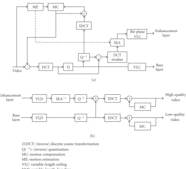
Figure1: (a) MPEG-4 FGS encoder and (b) MPEG-4 FGS decoder with shifting logic.
of existing codecs delivering additional quality and enabling various additional features.
When referring to FGS encoding, we actually refer to the encoding of the enhancement layer. For the encoding of the FGS enhancement layer, different techniques are possi-ble. Within MPEG, bit-plane DCT residue encoding [23] was chosen.
The enhancement layer receives as input the DCT residue values from the macroblock of a frame,1that is, the values
obtained after subtracting the dequantized coded DCT coef-ficients from the original DCT coefficients (Figure 1(a)). The resulting residue matrix inherits all characteristics of a DCT matrix. The difference with more traditional video encod-ing schemes is a novel approach to encode the residual val-ues. The FGS bit-plane DCT residue value encoding occurs by zig-zag scanning the values and by placing them in their
binaryform in a matrix (Figure 2). Note that the sign of a value is stored separately, so only the absolute value is used
1MPEG-4 traditionally uses the term video object plane (VOP) instead of a frame. Because our algorithms are independent of the actual used video encoding technology, we prefer to use the generic term “frame” through-out this paper.
for the binary representation. Abit planeis one row in this matrix, thus a sequence of 256 bits (in case of 16 16 mac-roblocks as used in MPEG-4 visual simple profile). Finally, the bit planes are translated to unique symbols encoded by a
variable-length coding(VLC) technique.
It is possible to (partially) dropbit planes, that is, not completely encoding or transmitting the bit plane, and as a result, using less bits for the enhancement layer. If one or more bit planes are dropped, the reconstructed values at the decoder side are less precise. These less accurate values can still be used to rebuild the macroblocks of the frame, but with a drop in visual quality. When dropping bit planes, large residue values are more likely to have a more correct recon-structed value than small residue values as the larger values will have bits in the upper, nondiscarded, bit planes.
10 0 3 0 1 0 0 7 0 2 0 0 0 0 0 2 0 0 0 0 0 0 2 0 0 0 0 0 0 0 0 0 0 0 0 0 0 0 0 0 0 0 0 0 0 0 0 0 0 .
.
. . ..
MSB 1 0 0 0 0 0 0 0 0 0 0 0 0 0 0 0 0 0
MSB-1 0 0 1 0 0 0 0 0 0 0 0 0 0 0 0 0 0 0
MSB-2 1 0 1 0 0 1 0 1 1 0 0 1 0 0 0 0 0 0
LSB 0 0 1 0 0 1 0 0 0 0 0 0 0 0 1 0 0 0
+ 1 + 1 1 +
+ + 1
0 1
0 1
Bit-plane MSB MSB-1 MSB-2 LSB
Figure2: Bit-plane representation of a DCT residue matrix.
of these shifted values appears in higher bit planes, they are placed more in front during encoding. This improves the probability that they will be present in the received—and probably truncated—enhancement layer. Hence, the proba-bility increases for all values within this DCT matrix to be reconstructed with a higher precision. As a result, this oper-ation can be used to support ROI. Obviously, the adequate information about the shifting is added to the resulting bit-stream so the decoder can perform the inverse transforma-tion. This is represented by the SEA 1
block inFigure 1(b). The algorithms described in the next section are generi-cally applicable and are not solely usable in MPEG-4 FGS, as they can be implemented in other codecs. We have chosen to use MPEG-4 FGS merely to clearly demonstrate and visual-ize the results of the object tracking algorithm presented in this paper.
4. OBJECT TRACKING
4.1. Introduction
One or more objects in a video scene can be identified man-ually or automatically through object segmentation tech-niques and the macroblocks can be placed into an ROI. Usu-ally, these objects will move in successive frames. We want to follow the movement of the objects so that we can automati-cally relocate the ROI. This process is calledobject tracking.
During the encoding of the base layer with an MPEG-4 visual simple profile encoder, the motion vectors are calcu-lated. This information is used to determine the motion of the tracked object, represented by theobject motion vector. This is illustrated by the dashed arrow inFigure 1(a). The ob-ject motion vector is used to move the ROI mask accordingly and, as such, to follow the motion of the object. Furthermore, as objects become larger or smaller, for example due to cam-era zooming, the mask must grow or shrink simultaneously with the object within.
In this section, new algorithms are introduced to enable object tracking and object motion. It works on a frame per
frame basis; for each frame, the following steps are executed. (i) First, the macroblocks that are part of the ROI are
identified as explained inSection 4.2.
(ii) Next inSection 4.3, the motion of the object within the ROI is determined, using the motion estimation infor-mation from the identified macroblocks. This results in the translation of the ROI.
(iii) Then, the ROI is resized automatically for optimal ob-ject fitting by using the motion estimation informa-tion. This is explained inSection 4.4.
(iv) Finally, to demonstrate the algorithm in MPEG-4 FGS, the relevant macroblocks of the updated ROI are identified and these are shifted by the shift value α. This is done by reusing the techniques explained in Section 4.2.
To end this section, a cloakingtechnology is introduced in Section 4.5 and the time complexity of the algorithms is given inSection 4.6. Pseudocode listings as an illustration to these algorithms are given in the appendix of this paper.
4.2. Selecting the macroblocks
The existing object tracking techniques in the compressed domain as discussed in Section 2 work on complete mac-roblocks. Also the default ROI functionality in MPEG-4 FGS utilizes a mask that is aligned with the macroblock bound-aries of a frame. This results in a direct mapping that deter-mines whether the macroblock is inside or outside the ROI. However, as macroblocks are, for example, 16 16 pixels, these rather large blocks of pixels are not suitable for fine-detailed object tracking.
We use a different and novel approach as we utilize an
(LX,LY) T(x,y)
TR
TC
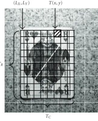
Figure3: A part of a frame where the card is selected as the ROI.
The ROI mask has dimensionsTC TR=8 10. An element of the
ROI mask is notated asT(x,y). The upper left corner of the ROI
mask has the coordinates (LX,LY). The ROI mask is a floating layer
on top of the frame and it is not aligned to the boundaries of the macroblock (represented by the white grid).
The enhanced ROI mask is represented by the matrixT with dimensionsTC TR;TCis the number of columns and TR is the number of rows in the enhanced ROI mask. The value of an element in matrixT—referred to as T(x,y)— represents the shift valueαthat has to be applied to the corre-sponding macroblock(s). Note that ifT(x,y)=0, no shifting will occur, allowing to create an arbitrary-shaped ROI hold-ing arbitrary-shaped objects. Further, an elementT(x,y) can represent any block size; here we use 8 8 pixels as block size which is a quarter of the default 16 16 pixels block size of macroblocks in MPEG-4 FGS. This creates a more fine-grained ROI mask, allowing a more neatly fitting selection of objects. The discussed algorithms can easily be modified to cope with any other size. In the remainder of the paper, we will assume 8 8 pixels as block size for the ROI mask elements and frame macroblocks of 16 16 pixels.
As the enhanced ROI mask floats on top of the frame, its location is also required. This is specified in pixel coor-dinates (denoted asLX andLY) and locates the upper left corner of the mask. Note that this location does not need to be aligned to a macroblock boundary. A visual representa-tion of the ROI mask as layer on top of the frame is shown in Figure 3.
Because of the decoupling of the ROI mask from the macroblocks, a mapping algorithm is required to determine which macroblocks are overlapped by the ROI. Each element T(x,y) in the enhanced ROI mask matrixToverlaps with at least one macroblock, denoted asmi,j. The indicesiandjare calculated by the formulas
i=
LX+ 8x
16
, j=
LY+ 8y
16
, (1)
wherei=0, 1,. . .,M1 andj=0, 1. . .,N1 (Mbeing the number of macroblocks in a frame horizontally andNbeing the number of macroblocks in a frame vertically).
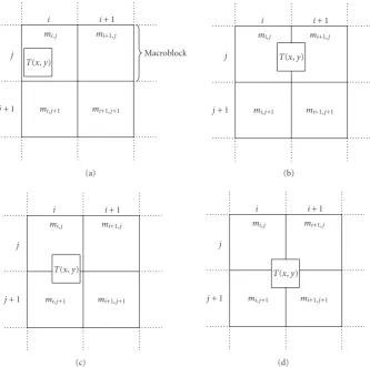
The computed macroblockmi,j is tagged as part of the ROI and receives the shift valueT(x,y). As T(x,y) repre-sents a block of 8 8 pixels, it is possible thatT(x,y) overlaps with other macroblocks, namelymi+1,j,mi,j+1, andmi+1,j+1
(Figure 4). InFigure 4(b), the 8 8 pixel block represented by T(x,y) overlaps with macroblock mi,j and macroblock mi+1,j. This can be mathematically expressed by the con-ditions (LX+ 8x) mod 16 > 8 and (LY+ 8y) mod 16 8. Other overlaps can be determined in a similar way. All mac-roblocks that are overlapped receive the shift valueT(x,y), hence in case ofFigure 4(b), the macroblocksmi,jandmi+1,j are set to this shifting value. If a macroblock already received a shifting value, then the highest shifting value is used. In case ofFigure 4(b), the macroblockmi,jreceives the highest shifting value from the ROI mask elementsT(x2,y1), T(x1,y1),T(x,y1),T(x2,y),T(x1,y),T(x,y), T(x2,y+ 1),T(x1,y+ 1), andT(x,y+ 1) assuming that x20,y10, andy+ 1< TC.
The time complexity of the described algorithm to deter-mine which macroblocks are overlapped by one ROI mask element T(x,y) is O(1): the calculation of i and j with the given formulas and the determination of overlaps with any neighboring macroblocks are done with a constant time complexity. Note that all multiplication and division opera-tions to select and to shift the macroblocks can be executed by a (fast) binary bit-shift operation.
4.3. Object motion
Object tracking by using the motion vectors of the object is only possible if the motion vector field is available. Tra-ditional base layer encoders, like implementations of the MPEG-4 visual simple profile specification, do not calculate the motion vector field of intracoded frames. As our algo-rithms need this vector field, this limitation of the encoder implementation can be circumvented by different strategies. For example, the encoder can be slightly modified, with minor overhead, in such a way that motion estimation is performed—hence the determination of the motion vector field—even for intracoded frames. The motion estimation can use the latest available frame as reference. As such, the dashed arrow inFigure 1always provides the object motion vector field, also for intracoded frames. Note that the mo-tion vector field for intracoded frames does not need to be stored into the resulting bit stream, so this modification of the encoder implementation does not affect the resulting en-coded video bit stream. Because there is at least one solution available, this and following sections assume that the motion vector field for the current frame is available.
In order to determine the motion of the object, the object motion vector (OMV) is calculated and is used to translate the upper left corner of the ROI mask resulting in adjusting theLXandLYvalues of the ROI mask. The OMV is calculated using the steps explained in the following paragraphs.
mi,j
i i+ 1
j
j+ 1 mi,j+1 mi+1,j+1 mi+1,j
T(x,y)
Macroblock
(a)
mi,j
i i+ 1
j
j+ 1 mi,j+1 mi+1,j+1 mi+1,j
T(x,y)
(b)
mi,j
i i+ 1
j
j+ 1 mi,j+1 mi+1,j+1 mi+1,j
T(x,y)
(c)
mi,j
i i+ 1
j
j+ 1 mi,j+1 mi+1,j+1 mi+1,j
T(x,y)
(d)
Figure4: Mapping of the ROI mask elementT(x,y) onto the macroblockmi,j. (a) The ROI mask element fits completely in the macroblock
mi,j. (b), (c), and (d) the ROI mask element overlaps with neighboring macroblocks.
are chosen depends on the location of T(x,y) as shown in Figure 5(motion estimation is in 4MV modus2). As a result,
four subblocks are selected and the motion vectors thereof are denoted as the vectorsMV1
x,ytoMV4x,y. The selection of the motion vectors is independent of the accuracy of the mo-tion vector; the implementamo-tion in MPEG-4 FGS uses half-pixel-element (pel) precision as MPEG-4 visual simple pro-file is used for the base layer.
Next, fouroverlapping percentages(P1 toP4) are
calcu-lated. They express the overlap of an elementT(x,y) with the four selected subblocks. In 4MV mode, first the horizon-tally (dx) and vertically (dy) overlaps ofT(x,y) with the first subblock are determined. This is illustrated byFigure 6and is calculated using the formulas
dx=8
LX+ 8x
mod 8=8
LXmod 8
,
dy=8
LY+ 8y
mod 8=8
LY mod 8
. (2)
2The 4MV mode divides a macroblock in 4 8
8 blocks (subblocks). The motion vectors of the four subblocks are calculated. For the macroblock mi,j, these are notated asMViγ,j,γ=1, 2, 3, 4. 1MV mode—where only
one motion vector per macroblock is calculated—can also be used by the algorithm.
Thedxanddyvalues allow the calculation of the overlapping percentagesPγ:
P1=dxdy
64 ,
P2=
8dx
dy 64 ,
P3=dx
8dy
64 ,
P4=
8dx
8dy
64 .
(3)
These percentagesPγare identical for all elements of the ROI maskT. This is because we work with a block size of 8 8 pixels for the ROI mask elements.
Next, the object motion vector for theT(x,y) element is determined (OMVx,y) as the weighted sum of the motion vectorsMVγx,yand the overlapping percentagesPγby
OMVx,y= 4
γ=1
MVγx,y
Pγ 4
γ=1Pγ
i i+ 1
j
j+ 1
T(x,y)
Macroblock MV1
i,j MVi2,j MVi1+1,j MVi2+1,j
MVi4,j MVi3+1,j MVi4+1,j
MV1
i,j+1 MVi2,j+1 MVi1+1,j+1MVi2+1,j+1
MVi3,j+1 MVi4,j+1 MVi3+1,j+1MVi4+1,j+1
(a)
i i+ 1
j
j+ 1
T(x,y)
MVi1,j MVi2,j MVi1+1,j MVi2+1,j
MVi3,j MVi4,j MVi3+1,j MVi4+1,j
MV1
i,j+1 MVi2,j+1 MVi1+1,j+1MVi2+1,j+1
MVi3,j+1 MVi4,j+1 MVi3+1,j+1MVi4+1,j+1
(b)
i i+ 1
j
j+ 1
T(x,y) MV1
i,j MVi2,j MVi1+1,j MVi2+1,j
MV3
i,j MVi4,j MVi3+1,j MVi4+1,j
MV1
i,j+1 MVi2,j+1 MVi1+1,j+1MVi2+1,j+1
MVi3,j+1 MVi4,j+1 MVi3+1,j+1MVi4+1,j+1
(c)
i i+ 1
j
j+ 1
T(x,y) MV1
i,j MVi2,j MVi1+1,j MVi2+1,j
MV3
i,j MVi4,j MVi3+1,j MVi4+1,j
MV1
i,j+1 MVi2,j+1 MVi1+1,j+1MVi2+1,j+1
MVi3,j+1 MVi4,j+1 MVi3+1,j+1MVi4+1,j+1
(d)
Figure5: Selecting the four appropriate motion vectors for ROI mask elementT(x,y), based on the overlap with the macroblocks.
Finally, the OMV is calculated as the average of all OMVx,yvectors:
OMV=
TC 1 x=0
TR 1
y=0 OMVx,y TCTR .
(5)
The resulting motion vector is the overall object motion vector of the ROI mask. This vector is used to adjust theLX andLY values.
Formula (4) has two additional constraints. These con-straints were added after evaluating and testing the algo-rithms and affect the overall results (seeSection 6). The first constraint removes the influence of motion vectors of too small overlapping areas. IfPγis smaller than a thresholdλ, the value ofPγis substituted by zero. This explains the rea-son of the divisor in (4).
The second constraint removes the influence of the mo-tion vectors being part of the border of an ROI mask as these could become less reliable after some iterations of the algo-rithm. IfT(x,y) is part of the border of the ROI mask, the vector OMVx,yis set to the null vector. In this case, the divi-sor in (5) is decreased with the number of ROI mask elements that fulfill with constraint (C.2).
These constraints can be expressed as follows: (C.1) Pγ=0 ifPγ< λ;
matrixT, that is, the calculation is linear to the number of ROI mask matrix elements. Indeed, an OMVx,yvector in for-mula (4) is calculated inO(1) as allMVγx,yand allPγ(with γ = 1,. . ., 4) are determined in O(1) for arbitraryT(x,y). ForMVγx,y, this is proven by the time-complexity analysis in Section 4.2. ThePγvalues are calculated by simple straight-forward computations, henceO(1). In addition, thesePγ val-ues are actually calculated only once as they are equal for all elements of the ROI mask.
4.4. Object resizing
Object motion, as discussed in the previous subsection, cap-tures the global motion of the object inside the ROI. During this motion, it is also possible that the “size” of the object changes, due to for example camera zooming or a change in the relative distance of the object to the camera. As a result, the ROI must also change in size, otherwise the ROI will be too small or too large for the larger, respectively, smaller ob-ject. We call thisROI resizing.
In total, there are six operations the size of an ROI can undergo:
(1.a) reduction in width; (1.b) stay equal in width; (1.c) enlarge in width; and
(2.a) reduction in height; (2.b) stay equal in height; (2.c) enlarge in height.
For every frame, one action is selected from (1.a), (1.b), and (1.c) and one action is selected from (2.a), (2.b), and (2.c). Both actions are executed as explained further in this section. The first step to enable automatic resizing of the ROI is to determine the two appropriate actions. To do so, the motion of the boundaries of the ROI is calculated using the formulas
ML= TR 1
y=0
OMV1 0,y TR ,
MR= TR 1
y=0
OMV1TC 1,y TR
,
MH=MLMR,
MU= TC 1
x=0
OMV2x,0
TC ,
MD= TC 1
x=0
OMV2x,TR 1 TC
,
(6)
MV=MUMD, (7)
OMV1x,yrepresents the first vector component of the vector OMVx,y; OMV2x,yis the second vector component of this vec-tor.MLrepresents the horizontal motion of the left-hand side ROI boundary, MR is the horizontal motion of the
right-dx
dy P1
P3 P2
P4
mi,j
Figure6: A macroblockmi,j divided into four 8 8 subblocks is
overlapped by anT(x,y) element. The figure shows how to
deter-minedxanddyand the overlapping percentagesP1toP4.
hand side ROI boundary, MU is the vertical motion of the topmost boundary, andMD denotes the vertical motion of the bottom boundary.MH is the overall horizontal motion andMV is the overall vertical motion.
Next, the two ROI resize actions are determined by the formulas
Action1= ⎧ ⎪ ⎪ ⎪ ⎨ ⎪ ⎪ ⎪ ⎩
(1.a) :MH<δ, (1.b) :δMHδ, (1.c) :MH> δ,
Action2= ⎧ ⎪ ⎪ ⎪ ⎨ ⎪ ⎪ ⎪ ⎩
(2.a) :MV <δ, (2.b) :δMVδ, (2.c) :MV> δ,
(8)
δ is a threshold the motion of the ROI boundaries has to reach before the reducing or enlarging of the ROI mask takes place. A value of half the size of the block that aT(x,y) ele-ment represents proves to be a good value (seeSection 6).
Knowing the required actions, the resizing of the ROI can take place. In case of action (1.a), the ROI matrix T is re-placed by a new matrixT¼
with dimensions ((TC1) TR). The shifting values of the new matrixT¼
are a linear combi-nation of the values of matrixT, expressed by the formula
T¼ (x,y)=
TCx1
T(x,y) + (x+ 1)T(x+ 1,y) TC
, (9)
where
x=0, 1,. . .,TC2, y=0, 1,. . .,TR1. (10) This formula reduces the ROI matrix T with one column, however it is possible that this is insufficient. IfMH+δ <δ, we repeat the reduction formula (9). A similar procedure is executed in case of action (2.a).
Finally, in case of an enlarging size, the ROI matrixTis replaced by a new matrixT¼
with dimensions ((TC+ 1) TR) in case of (1.c) and (TC (TR+ 1)) in case of (2.c). The values of new matrixT¼
are a linear combination of the values of matrixT, analog to the formula (9). This enlarging must also be repeated if necessary.
After applying the appropriate resizing actions, a surplus betweenδandδremains. This value is added to the results of the calculation of (6) and (7) for the next frame, in other words we cumulate the motion of the ROI boundaries over multiple frames.
The time complexity of the algorithm to resize the ROI is determined as follows. First, the algorithm calculates the hor-izontal and vertical motions (i.e.,MHandMV) according to the formulas (6) and (7). These formulas aggregate over, re-spectively, the number of rows and the number of columns of the ROI mask. This results in a time complexity ofO(TR) for formula (6) andO(TC) for formula (7). The outcome of the formulas is used to determine the resizing action of the ROI according to the formula (8). With regard to the time com-plexity, this finding does not alter the time complexity. Next, the actual resizing of the ROI matrix is performed, depen-dent on the type of action determined in the previous step. If no resizing occurs (actions (1.b) and (2.b)), no additional steps must be performed. In case of a vertical reduction (ac-tion (1.a)), the formula (9) must be executed. This formula creates a new matrix inO((TC1)TR)=O(TCTR)=O(n), that is, linear to the number of elements in de ROI matrix. For all other actions ((1.c), (2.a), and (2.c)), the time com-plexity can be deduced in a similar way, thusO(n) for each action. When combining two resize actions or a resize action that must be repeated several times, the overall time com-plexity remainsO(n).
Adding the time complexityO(TR) to calculate formula (6) and theO(TC) to calculate formula (7) to the time com-plexity for the resizing actions (O(n)), the time complex-ity for the ROI resizing algorithm isO(n). In the optimal case (if no resizing is done), the time complexity is Ω(m), m = max(TC,TR), thus linear to the maximum number of rows or columns of the ROI mask matrix.
4.5. Cloaking
The algorithms discussed in this section enable the creation of an ROI maskT, containing elementsT(x,y) that repre-sent blocks of 8 8 pixels. By setting a shift value to zero, it is possible to create arbitrary-shaped ROI masks. However to determine the object motion as described inSection 4.3, the motion vectors for allT(x,y) elements are determined and used in the overall object motion vector calculations. If the object inside the ROI is not rectangular, the calculation of the OMV uses all motion vectors within this ROI, even those that are not associated with this object. This is not desirable as these are associated with another object which might exhibit another motion trajectory. In addition, sometimes it is desir-able to differentiate between the area to improve the visual quality and the object that is being tracked as the creation of a region slightly larger than the object itself improves visual perception.
Figure7: A part of a frame of the video sequence “hall monitor.” The black grid represents the cloaking layer which coincides with
the ROI mask matrixT. The hatched parts indicate the cloaking
matrix elements larger than zero. The motion vectors of the parts that are not hatched will not be used to determine the overall object motion OMV.
To solve these concerns, an additionalcloaking layer is used that allows full separation of the visually important re-gion and the object that is being tracked.
The cloaking layer is represented by a new matrix C which has identical dimensions as matrixTand consists of binary values indicating if the OMVx,yvector must be taken into account in the overall object motion vector calculations. The determination of the values in the matrixCis done by a manual selection, similar to the determination of the object that must be followed, that is, the initial determination of matrixTand the coordinates (Lx,Ly). This results in a third constraint for formula (4):
(C.3) OMVx,y=0 ifC(x,y)=0.
Similar as for constraint (C.2), the divisor in (5) is decreased with the number of the matrix element that fulfills constraint (C.3).
InFigure 7a part of a frame is shown of the “hall mon-itor” sequence (see Figure 8 for the complete frame). The white grid represents the macroblocks, the black grid is the enhanced ROI mask matrix T and the cloaking matrix C, which coincide. The hatched parts indicate the cloaking ma-trix elements larger than zero. Only the motion vectors of the hatched parts will be used to determine the overall object motion OMV.
Figure8: A picture from the “hall monitor” test sequence.
is extended in such a way that not only matrixTis adjusted to the new size, but also cloaking matrixC. This is done iden-tical to the creation of matrixT¼
as discussed in the previous section resulting in a new matrixC¼
.
The cost in terms of time complexity for adding an addi-tional cloaking layer is relevant during the resize operation. As the same resizing formulas are executed as for the ROI mask matrixT, the time complexity is the same. Hence, the time complexity of resizing the ROI matrixTand the cloak-ing matrixCisO(2n)=O(n).
4.6. Time-complexity analysis
To conclude this section, an overall time-complexity analysis of our algorithms is presented. Our algorithms enabling au-tomatic object tracking in the compressed domain are based on two principles:object motionas described inSection 4.3 andobject resizing—resulting inROI resizing—as described inSection 4.4.
For every frame, both algorithms are executed. As demonstrated in the previous sections, both have a (worst-case) time complexity ofO(n), meaning that the time com-plexity is linear to the total number of elements n in the ROI mask matrix. Because both algorithms are sequential, the global time complexity for our algorithms is alsoO(n).
As such, using our lightweight object tracking algorithms implies adding an additional time cost that is linear to the size of the object we want to track. Note that the size of the object is normally smaller than a complete frame. Further-more, performance analysis of the MPEG-4 reference soft-ware encoder and MPEG-4 FGS reference softsoft-ware encoder in [24,25] shows that the encoder needs tens of millions of operations per second. As such, our lightweight algorithms are only a very small fraction of the total required encoding time. Hence, object tracking in the compressed domain by using the presented algorithms is feasible, even for real-time and streaming applications, on the condition that the object is known through the matricesTandC, and the initial coor-dinatesLxandLy.
Finally, it must be noted that the object tracking algo-rithms do not add any complexity to the video decoder. All
Figure9: A picture from the “crew” test sequence.
algorithms, and associated time complexity, are part of the video encoder.
5. MATERIALS AND METHODS
In the remainder of the paper, we evaluate the accuracy of our lightweight object tracking algorithms. First, we created a video of a playing card moving from right to left against a nonuniform background, while the camera is zooming in. The first frame shows the playing card at the right-hand side. Throughout the frames, the card moves towards and outside the left boundary of the frame, until only a small piece is vis-ible in the last frame. Meanwhile, the card is more than dou-bled in size due to the camera zooming operation. The video has a resolution of 320 240 resulting in 20 15 macroblocks and has a length of 501 frames. A picture from the video se-quence is shown inFigure 3.
We also used two well-know test sequences, namely “hall monitor” (consisting of 101 frames with a CIF resolution of 352 288) and “crew” (consisting of 50 frames with an HD resolution of 1280 720). One can see a picture of the former inFigure 8and a picture of the latter inFigure 9. The first se-quence was chosen because the object being tracked is scaled down, the second sequence was chosen because of the larger resolution and the many moving objects.
To test the algorithms, we need to validate them. We asked four different persons who have no visual defects to indicate for each frame the smallest possible rectangular re-gion containing the object, that is, the card for the first test sequence, the man on the left in “hall monitor” sequence and the man on front right in the “crew” sequence. All mac-roblocks that hold (a part of) this region are marked and stored as the object indicationfor the given frame. The ob-ject indication for the first frame was given as an input, the remaining frames were tagged manually. From the four re-sulting sets of object indications, we distilled one reference set for each test sequence. In the next section, the construc-tion of these sets are discussed.
for the first frame for the manual marking. In the first se-quence, the playing card fits perfectly in the ROI mask, hence the cloaking matrixC is completely filled with values larger than 0. For the other two sequences, the cloaking matrixC is used so that only the motion vectors of the human form are taken into account.Figure 7depicts the cloaking matrix for the “hall monitor” sequence. All values of the matrixT are α = 9. Next, different parameters were used to inves-tigate their optimal settings and their influence on the re-sults:
(i) (C.1):λ=0.00,λ=0.05,λ=0.10,λ=0.15,λ=0.20, λ=0.25;
(ii)δin formula(8):δ=2,δ=4,δ=8, andδ=16; (iii)applying and not applying (C.2).
It is necessary thatλ0.25 in constraint (C.1). If not and the ROI mask is located in such a way that none of the over-lapping percentages are larger thanλ, then constraint (C.1) is never met, and consequently OMV will be the null vec-tor. As a result, the valuesLXandLY do not change, and the ROI mask will not move. For all subsequent frames, the same event will occur, keeping the ROI mask at the same location. All different combinations are encoded with an I(P£
) GOP3 structure. During the encoding, for each frame the
macroblocks that are marked for selective enhancement by the algorithms are logged.
6. RESULTS AND DISCUSSION
6.1. Results
First, we elaborate on the results of the manual object indica-tion for the given video, and this by comparing the different indications given by the four persons. To create the reference set for the first test sequence, 473 object indications can be selected in a trivial manner as there is a majority in the four-object-indication sets. In order to have for each of the 500 frames one-object indication, 27 object indications must be added to the reference set. To do this, we determine the per-son that contributed the most indications to the 473 object indications and we select the remaining 27 object indications from this person. This results in a reference set of 500 object indications, for each frame one indication.
The test reference sets for the “crew” and “hall monitor” sequences are determined in a similar way.
It can be observed that selecting the “correct” region is, even for humans, a difficult task. Further investigation of the results shows that most often, the four opinions only differ in one row or one column of macroblocks.
Next, the logs that were created during the encoding of the video are compared to the constructed reference set and compared to the reference set accepting a minor dissimilar-ity of one row or one column. The criterion for evaluation is the percentage of identical object indications: the higher this
3The GOP structure specifies the sequence of frame types. In this notation, I(P£
) means that the encoded video starts with an I-frame, followed by only P-frames.
value is, the better the automatic algorithm performs. This result in two measurements for each of the different test se-quences:
(M.1) compare to the reference set;
(M.2) compare to the reference set and accept a dissimilarity of one row or one column as correct.
The results for the three sequences can be found in Table 1.
6.2. Discussion
The relationship of the results for (M.1) and (M.2) is as ex-pected. Obviously, the results that accept a dissimilarity of one row or one column as correct (M.2) are always better than the cases were such dissimilarity is not accepted as cor-rect (M.1).
We observe that the value ofλ does not have a signif-icant influence on the results. Because formula (4) weights the value of the motion vectorMVγx,ywith overlapping per-centagePγ, the influence of small overlapping areas is auto-matically reduced.
We also observe that our algorithms are also insensitive to sudden motion changes. Indeed, if the object stops, the cal-culation of the object motion vector will result in a null vec-tor as the motion vecvec-tors associated with the object will also be the null vector. Hence, the ROI mask will not be displaced. If the object starts moving again, the motion vectors will re-flect this motion and the object motion vector will rere-flect the displacement of the object, regardless of the direction of this last motion. In fact, the object that is being tracked in the “hall monitor” sequence stops for a few frames and contin-ues to move in another direction.
Table1: Test results (%).
Card Hall monitor Crew
Parameters C.2 Not C.2 C.2 Not C.2 C.2 Not C.2
δ λ M.1 M.2 M.1 M.2 M.1 M.2 M.1 M.2 M.1 M.2 M.1 M.2
2
0.00 9 18 8 13 5 36 5 37 18 68 14 70
0.05 8 18 8 13 5 36 5 36 16 68 14 66
0.10 10 19 8 14 5 36 5 36 16 68 14 68
0.15 10 19 7 14 5 36 5 37 16 70 8 48
0.20 11 20 7 14 4 38 5 38 8 46 8 42
0.25 11 20 7 19 4 38 6 44 14 68 14 70
4
0.00 75 96 30 59 11 85 10 85 14 78 14 78
0.05 75 96 30 60 16 87 10 85 14 78 14 78
0.10 76 96 31 61 12 86 10 85 14 78 14 78
0.15 76 96 32 60 21 88 10 85 14 76 14 76
0.20 74 96 30 60 20 86 11 86 14 72 14 72
0.25 71 96 33 60 20 87 12 86 14 72 14 72
8
0.00 15 34 14 36 2 34 2 42 10 72 10 72
0.05 15 34 14 36 2 34 2 42 10 72 10 72
0.10 15 34 14 36 2 34 2 42 10 72 10 72
0.15 15 36 14 36 2 34 2 44 10 72 10 72
0.20 15 35 14 35 2 34 2 42 10 72 10 72
0.25 15 34 14 34 2 34 2 44 10 72 10 72
16
0.00 14 28 14 29 2 20 2 26 10 48 10 48
0.05 14 28 14 29 2 20 2 26 10 48 10 48
0.10 14 28 14 30 2 20 2 25 10 48 10 48
0.15 14 28 13 30 2 20 4 60 10 48 10 48
0.20 14 28 13 30 2 21 2 25 10 46 10 46
0.25 14 28 13 30 2 20 2 25 10 46 10 46
foreach framedo // Start procedure // Initialization frame Algorithm 2
OMV=calculate OMV usingAlgorithm 3
// Translated mask
LX=LX+ OMV1
LY =LY+ OMV2
// Perform resize actions Algorithm 5
Algorithm 6
// Determine macroblock shifting Values
Algorithm 7 end
Algorithm1: Main algorithm.
The table also reveals the big impact of constraint (C.2) for the “card” sequence, in particular whenδ is set to 4. It is clear from the test that the border of an ROI mask is less reliable, especially after some iterations. To avoid the same
// Calculatedx,dy
dx=8(L
Xmod 8)
dy=8(LY mod 8)
// CalculatePγand4
γ=1Pγ P1=(d
xdy)/64 P2=(d
x(8dy))/64 P3=((8
d
x)d
y)/64
P4=((8
dx)(8dy))/64
ifP1< λthenP1=0
ifP2< λthenP2=0
ifP3< λthenP3=0
ifP4< λthenP4=0 Psum=P1+P2+P3+P4
Algorithm2: Initialization for each frame.
event to occur whenλ >0.25 as explained inSection 5, the constraint (C.2) is never applied if the ROI mask is too small in size. This is realized by (C.2), its conditionsTC > 2, and TR>2. Constraint (C.2) should always be enabled in combi-nation withδ=4 as this always generates better results.
// For all matrix elementsT
forx=0 toTC1 do
fory=0 toTR1 do
// GetMV1
x,yusingAlgorithm 4
// GetMV2
x,yusingAlgorithm 4
// GetMV3x,yusingAlgorithm 4
// GetMV4
x,yusingAlgorithm 4
// Calculate formula (4)
OMVx,y=(MV1x,y+MV2x,y+MV3x,y+
MV4
x,y)/Psum
// Apply constraint (C.2)
if (((x=0) or (x=TC1)) and
(TC>2)) or (((y=0) or
(y=TR1)) and (T
R>2)) then
OMVx,y=0
C2Counter++ end
end end
// Calculate overall object motion result.
forx=0 toTC1 do
fory=0 toTR1 do
OMV+=OMVx,y
end end
OMV=OMV/((TCTR)C2Counter)
Algorithm3: Calculate OMV.
zooming operation, settingδ larger than the optimal value will result in a too small matrixT. Therefore, if the matrix Tis smaller than the genuine object, adding the motion vec-tors of the elements on the edges of matrixTmeans incorpo-rating the motion vectors of the actual object being tracked; this is good. For video sequences where the matrixTis larger than the actual object, not enabling constraint (C.2) gives a worse result as the motion vectors outside the actual object are taken into account.
The reason we do not observe this large influence for the two other sequences is because of the usage of the cloaking matrixC. Indeed, because the used cloaking matrix—such as the one depicted inFigure 7—removes most macroblocks that are part of the border, the enabling or disabling of con-straint (C.2) hardly influences the results for these sequences. To conclude, the most optimal settings for a video se-quence are
(i) (C.1):λ0.25;
(ii)(C.2): enabled or use a cloaking matrixC; (iii)δ: 4.
Our automatic algorithm reaches near perfection when comparing to the reference set and allowing one row or
col-// DetermineMVx,y
if (LX+ 8dx) mod 168 and
(LY+ 8dy) mod 168 then
//Figure 5(a)
MV1x,y=MV1i,j
MV2
x,y=MV2i,j
MV3
x,y=MV3i,j
MV4
x,y=MV4i,j
else if (LX+ 8d
x) mod 16>8 and
(LY+ 8dy) mod 168 then
//Figure 5(b)
MV1
x,y=MV2i,j
MV2
x,y=MV1i+1,j
MV3
x,y=MV4i,j
MV4
x,y=MV3i+1,j
else if (LX+ 8dx) mod 168 and
(LY+ 8dy) mod 16>8 then
//Figure 5(c)
MV1
x,y=MV3i,j
MV2
x,y=MV4i,j
MV3
x,y=MV1i,j+1 MV4x,y=MV2i,j+1
else if (LX+ 8dx) mod 16>8 and
(LY+ 8dy) mod 16>8 then
//Figure 5(d)
MV1
x,y=MV4i,j
MV2
x,y=MV3i+1,j
MV3x,y=MV2i,j+1 MV4
x,y=MV1i+1,j+1
end
Algorithm4: DetermineMVx,y.
umn mismatch (M.2) for the “card” sequence: 96.1% on av-erage over the six possible values forλ. Comparing to the reference set without allowing one row or column mismatch (M.1) gives an average result of 74.5% for this first test se-quence.
For the “hall monitor” sequence, using the optimal set-tings, our algorithms achieve on average 86.5% when allow-ing one row or column mismatch (M.2). However, if a mis-match is not allowed (M.1), the results are much lower in comparison to the first sequence. The good results for (M.2) indicate that mostly there is only one row or one column mis-match. Looking more into detail, we see that the automatic algorithm marks the object too large, hence one column or one row too much. While this restrains the percentages for (M.1), the visual perception is not negatively influenced by enhancing a little more than the object. Furthermore, the mismatch does not propagate over successive frames, so the algorithms are still useful.
MH=calculate formula (6)
// Perform resize actions horizontal ifMH<δthen
// Action (1.a) repeat
forx=0 toTC2 do
fory=0 toTR1 do
T¼
(x,y)=
TCx1
T(x,y) + (x+ 1)T(x+ 1,y)
TC
end end
MH=MH+δ
untilMH>δ
end
ifMH> δthen
// Action (1.c) repeat
forx=0 toTCdo
fory=0 toTR1 do
T¼
(x,y)=
TCx
T(x,y) + (x)T(x1,y) TC
end end
MH=MHδ
untilMHδ
end
Algorithm5: Perform resize actions horizontal.
results are lower than the “card” sequence—particularly when comparing to (M.1)—, it must be noted that this se-quence is far more complex as it contains more (moving) objects, a moving background with similar texture and col-orization of the object that is being tracked, abrupt lumi-nance changes due to flash photography, and so on.
Nevertheless, these results illustrate the usability of our algorithms to enable a lightweight and real-time object track-ing in the compressed domain.
7. CONCLUSIONS
In this paper, we have discussed novel algorithms allowing a video encoder to automatically track an object. These al-gorithms have a very low time complexity which is linear to the size of the object, making them very useful for real-time and streaming applications. We make use of the motion vec-tor field calculated by the encoder’s motion estimation algo-rithms to capture the overall motion of the tracked object. We also introduced an algorithm that allows an encoder to cope with the “enlargement” and “shrinking” of an object. All our algorithms are capable of tracking any kind of ob-jects in a video stream. Furthermore, our algorithms are not bound to the (relatively large) size of a macroblock; we use
MV=calculate formula (7)
// Perform resize actions vertical ifMV<δthen
// Action (2.a) repeat
forx=0 toTC1 do
fory=0 toTR2 do
T¼
(x,y)=
TRy1
T(x,y) + (y+ 1)T(x,y+ 1)
TR
end end
MV=MV+δ
untilMV>δ
end
ifMV> δthen
// Action (2.c) repeat
forx=0 toTC1 do
fory=0 toTRdo
T¼
(x,y)=
TRy
T(x,y) + (y)T(x,y1) TR
end end
MV=MVδ
untilMVδ
end
Algorithm6: Perform resize actions vertical.
a fine grid on top of a frame so the algorithms can track any object in a more detailed way.
All our novel methods presented in this paper are generic and can be implemented in any codec that calculates the mo-tion vector field. However, the results depend on the spe-cific kind of the motion estimation algorithm of the video encoder. For testing and evaluating purposes, we have im-plemented the algorithms within the MPEG-4 FGS reference software codec. We used the region-of-interest capabilities of this codec to visualize the results of the algorithms. A second layer was introduced enabling us to differentiate between the ROI and the (possibly smaller) objects within. Three test se-quences were used to evaluate the influence of various pa-rameters. The results of our algorithms were compared to manually constructed reference sets, so an optimal param-eter set was dparam-etermined.
From these results, we can conclude that these novel lightweight algorithms are capable of tracking objects in complex scenes, can handle scaled down or scaled up objects, and are independent of the resolution of the video stream.
APPENDIX
PSEUDOCODE ALGORITHMS
// For all matrix elementsT
forx=0 toTC1 do
fory=0 toTR1 do
// Determineiandj
i=trunc((LX+ 8x)/16) j=trunc((LY+ 8y)/16)
// Set shifting values to macroblocks
if (LX+ 8dx) mod 168 and
(LY+ 8dy) mod 168 then
//Figure 4(a)
mi,j=max(mi,j,T(x,y))
else if (LX+ 8dx) mod 16>8 and
(LY+ 8d
y) mod 168 then
//Figure 5(b)
mi,j=max(mi,j,T(x,y))
mi+1,j=max(mi+1,j,T(x,y))
else if (LX+ 8dx) mod 168 and
(LY+ 8dy) mod 16>8 then
//Figure 5(c)
mi,j=max(mi,j,T(x,y))
mi,j+1=max(mi,j+1,T(x,y))
else if (LX+ 8dx) mod 16>8 and
(LY+ 8d
y) mod 16>8 then
//Figure 5(d)
mi,j=max(mi,j,T(x,y))
mi+1,j=max(mi+1,j,T(x,y))
mi,j+1=max(mi,j+1,T(x,y)) mi+1,j+1=max(mi+1,j+1,T(x,y))
end end end
Algorithm7: Determine shifting values for all macroblocks.
ACKNOWLEDGMENTS
The authors would like to thank Tom Caljon of the Vrije Uni-versiteit Brussel, Department of Electronics and Informatics for his valuable input and testing during the writing of this paper. The research activities that have been described in this paper were funded by Ghent University, the Interdisciplinary Institute for Broadband Technology (IBBT), the Institute for the Promotion of Innovation by Science and Technology in Flanders (IWT), the Fund for Scientific Research-Flanders (FWO-Flanders), the Belgian Federal Science Policy Office (BFSPO), and the European Union.
REFERENCES
[1] A. J. Lipton, H. Fujiyoshi, and R. S. Patil, “Moving target
clas-sification and tracking from real-time video,” inProceedings
of the 4th IEEE Workshop on Applications of Computer Vision (WACV ’98), pp. 8–14, Princeton, NJ, USA, October 1998. [2] M. van der Schaar and Y.-T. Lin, “Content-based selective
en-hancement for streaming video,” inProceedings of IEEE
Inter-national Conference on Image Processing (ICIP ’01), vol. 2, pp. 977–980, Thessaloniki, Greece, October 2001.
[3] H. Wang and S.-F. Chang, “A highly efficient system for
auto-matic face region detection in MPEG video,”IEEE Transactions
on Circuits and Systems for Video Technology, vol. 7, no. 4, pp. 615–628, 1997.
[4] C. Bregler, “Learning and recognizing human dynamics in
video sequences,” inProceedings of the IEEE Computer
Soci-ety Conference on Computer Vision and Pattern Recognition, pp. 568–574, San Juan, Puerto Rico, USA, June 1997.
[5] A. Cavallaro, O. Steiger, and T. Ebrahimi, “Semantic video analysis for adaptive content delivery and automatic
descrip-tion,”IEEE Transactions on Circuits and Systems for Video
Tech-nology, vol. 15, no. 10, pp. 1200–1209, 2005.
[6] O. Sukmarg and K. R. Rao, “Fast object detection and
seg-mentation in MPEG compressed domain,” inProceedings of
IEEE Region 10 Annual International Conference on TENCON (TENCON ’00), vol. 3, pp. 364–368, Kuala Lumpur, Malaysia, September 2000.
[7] S.-Y. Chien, Y.-W. Huang, and L.-G. Chen, “Predictive wa-tershed: a fast watershed algorithm for video segmentation,”
IEEE Transactions on Circuits and Systems for Video
Technol-ogy, vol. 13, no. 5, pp. 453–461, 2003.
[8] S. Dasiopoulou, V. Mezaris, I. Kompatsiaris, V.-K. Papastathis, and M. G. Strintzis, “Knowledge-assisted semantic video
ob-ject detection,”IEEE Transactions on Circuits and Systems for
Video Technology, vol. 15, no. 10, pp. 1210–1224, 2005. [9] V. Mezaris, I. Kompatsiaris, N. V. Boulgouris, and M. G.
Strintzis, “Real-time compressed-domain spatiotemporal seg-mentation and ontologies for video indexing and retrieval,”
IEEE Transactions on Circuits and Systems for Video
Technol-ogy, vol. 14, no. 5, pp. 606–621, 2004.
[10] M. Isard and A. Blake, “Contour tracking by stochastic
prop-agation of conditional density,” inProceeding of 4th European
Conference on Computer Vision (ECCV ’96), vol. 1, pp. 343– 356, Cambridge, UK, April 1996.
[11] W.-N. Lie and R.-L. Chen, “Tracking moving objects in
MPEG-compressed videos,” inProceedings of IEEE
Interna-tional Conference on Multimedia and Expo (ICME ’01), pp. 1172–1175, Tokyo, Japan, August 2001.
[12] R. Achanta, M. Kankanhalli, and P. Mulhem, “Compressed domain object tracking for automatic indexing of objects in
MPEG home video,” inProceedings of IEEE International
Con-ference on Multimedia and Expo (ICME ’02), vol. 2, pp. 61–64, Lusanne, Switzerland, August 2002.
[13] S.-M. Park and J. Lee, “Object tracking in MPEG compressed
video using mean-shift algorithm,” inProceedings of the Joint
Conference of the 4th International Conference on Information, Communications and Signal Processing and the 4th Pacific-Rim Conference on Multimedia (ICICS-PCM ’03), vol. 2, pp. 748– 752, Singapore, December 2003.
[14] L. Favalli, A. Mecocci, and F. Moschetti, “Object tracking for
retrieval applications in MPEG-2,”IEEE Transactions on
Cir-cuits and Systems for Video Technology, vol. 10, no. 3, pp. 427– 432, 2000.
[15] W. Li, “Overview of fine granularity scalability in MPEG-4
video standard,”IEEE Transactions on Circuits and Systems for
Video Technology, vol. 11, no. 3, pp. 301–317, 2001.
[16] J.-R. Ohm, “Advances in scalable video coding,”Proceedings of
the IEEE, vol. 93, no. 1, pp. 42–56, 2005.
[17] F. Pereira and T. Ebrahimi, Eds.,The MPEG-4 Book,
Prentice-Hall, Englewood Cliffs, NJ, USA, 2002.
[18] A. Puri and T. Chen, Eds.,Multimedia Systems, Standards and
[19] J. Ascenso and F. Pereira, “Drift reduction for a H.264/AVC fine grain scalability with motion compensation architecture,” inProceedings of International Conference on Image Processing (ICIP ’04), vol. 4, pp. 2259–2262, Singapore, October 2004. [20] M. Doma ´nski, L. Blaszak, and S. Ma´ckowiak, “AVC video
coders with spatial and temporal scalability,” inProceedings of
Picture Coding Symposium (PCS ’03), pp. 41–46, Saint Malo, France, 2003.
[21] K. Ugur, G. Louizis, P. Nasiopoulos, and R. Ward, “Extremely fast selective enhancement method for fine granular scalable
enabled H.264 video,” inProceedings of IEEE Canadian
Con-ference on Electrical and Computer Engineering (CCECE ’03), vol. 2, pp. 1103–1106, Montreal, Canada, May 2003.
[22] K. Ugur and P. Nasiopoulos, “Combining bitstream switching and FGS for H.264 scalable video transmission over varying
bandwidth networks,” inIEEE Pacific Rim Conference on
Com-munications Computers and Signal Processing (PACRIM ’03), vol. 2, pp. 972–975, Victoria, BC, Canada, August 2003.
[23] F. Ling, W. Li, and H. Sun, “Bitplane coding of DCT coeffi
-cients for image and video compression,” inVisual
Communi-cations and Image Processing, vol. 3653 ofProceedings of SPIE, pp. 500–508, San Jose, Calif, USA, January 1999.
[24] F. Cavalli, R. Cucchiara, M. Piccardi, and A. Prati, “Per-formance analysis of MPEG-4 decoder and encoder,” in
Proceedings of 4th EURASIP-IEEE International Symposium on Video/Image Processing and Multimedia Communications (VIPromCom ’02), pp. 227–231, Zadar, Croatia, June 2002. [25] O. Lehtoranata and T. D. H¨am¨al¨ainen, “Complexity analysis
of spatially scalable MPEG-4 encoder,” inIEEE International
Symposium on System-on-Chip, pp. 57–60, Tampere, Finland, November 2003.
Robbie De Sutterreceived the M.S. degree in computer science from Ghent Univer-sity, Belgium, in 1999. He joined the Mul-timedia Lab in 2001, where he obtained his Ph.D. degree in 2006. His research interests include video coding technologies, usage-context modeling and negotiation, and con-tent adaptation.
Koen De Wolfreceived the M.S. degree in computer science from Ghent University, Belgium, in 2003. In that year, he joined the Multimedia Lab, where he is currently working towards the Ph.D. degree. His re-search interests include video coding tech-nologies, more in particular scalable video coding, interlayer prediction, and scalable motion information.
Sam Lerouge received his M.S. degree in computer science from Ghent University, Belgium in 2001. Since then, he started working towards the Ph.D. degree in the Multimedia Lab, which he obtained in 2005. His research focused on maximizing the vi-sual quality in constrained environments. Since 2006, he is working as a Project Man-ager for the Regionale Media Maatschappij, which supports two local television chan-nels, where he is focusing on digital TV applications.
Rik Van de Walle received his M.S. and Ph.D. degrees in engineering from Ghent University, Belgium in 1994 and 1998, re-spectively. After a visiting scholarship at the University of Arizona (Tucson, USA), he re-turned to Ghent University, where he be-came Professor of multimedia systems and applications, and Head of the Multimedia Lab. His current research interests include multimedia content delivery, presentation