•
UNISYS
DCP Series
TCP-IP Stack
NO WARRANTIES OF ANY NATURE ARE EXTENDED BY THE DOClJ.4ENT. Any product and related material disclosed herein are only furnished pursuant and subject to the terms and conditions of a duly executed agreement to purchase or lease equipment or to license software. The only warranties made by Unisys Corporation, if any, with respect to the products described in this document are set forth in such agreement. Unisys Corporation cannot accept any financial or other responsib~ity that may be the result of your use of the information in this document or software material, including direct, indirect, special, or consequential damages.
You should be very careful to ensure that the use of this information and/or software material complies with the laws, rules, and regulations of the jurisdictions with respect to which it is used. The information contained herein is subject to change without notice. Revisions may be issued to advise of such changes and/or additions.
Correspondence regarding this publication should be forwarded to Unisys Corporation by addressing remarks to Communication Systems Product Information, Salt Lake City Publications, MS B2B07, 322 North 2200 West, Salt Lake City, UT 84116-2979, U.S.A.
RESTRICTED - Use, reproduction, or disclosure is subject to the restrictions set forth in
DV'n~llf't InfnV'rY)~tif"'\n
I I VUU\,.,l II II VI I I IUlIUI I
Announcement
o New Release 0 Revision .. Update 0 New Mail Code
Title:
DCP Series TCP-IP Stack Configuration and Operations Guide Level 2R2B
This Product Information Announcement announces the release and availability of the OCP Series rCP-IP Stack Configuration and Operations Guide, Level 2R2B (7831 5546-110). This information provides update pages for the
2R2 release, 7831 5546-100.
The Unisys OCP Series TCP-IP Stack program product supports TCP liP communications across various
subnetworks for Telcon software on
a
Unisys Distributed Communications Processor (DCP).The pages in this update replace similarly numbered pages in 7831 5546-100.
TCP-IP Stack level 2R2B includes the following new features:
• Supports the 802.5 Token Ring inte!!igent line module (!L~,~)
• Supports TN3270 terminal emulators
• Supports DCA session establishment over a Tep liP network
Note: The official term for
"os
1100" has been changed to"os
2200." Books in this library have not yet changed all references ofos
1100 toos
2200 at this printing.To order additionai copies of this docurnent
• United States customers, call Unisys Direct at 1-800-448-1424. • All other customers, contact your Unisys Sales Office.
e
UNISYS
Product Information
Announcement
o New Release • Revision o Update 0 New Mail Code
Title:
DCP Series TCP-IP Stack Confi&uration and Operations Guide Level 2R2
This Product Information Announcement announces the release and availability of the OCP Series rCP-IP Stack
Configuration and Operations Guide, Level2R2 (7831 5546-100j.
The Unisys OCP Series TCP-JP Stack program product supports TCP/IP communications across various subnetworks for Telcon software on a Unisys Distributed Communications Processor (DCP).
TCP-JP Stack works with the following DCP Series software, which provides the necessary hardware connectivity:
•
LAN Platform for communications over 802.3 and FODllocal area networks (LANs)•
X.25 Packet Switched Communications Software (PSCS) for communications over X.25 packet switchednetworks, including the Defense Data Network (DON), public data networKS (PONs), and private packet networks. TCP-JP Stack supports IP communications across the following networks:
• 802.2, 802.3, and FODI local area networks (LANs)
•
X.25 packet switched networks, including the Defense Data Network (DDN), public data networks (PDNs), and private packet networks•
Unisys DNS networks• as
11 OO-to-DCP host channelsIn addition, TCP-JP Stack enables communication between DCA and Tep/IP networks.
TCP-JP Stack Level 2R2 includes the following new features:
•
Supports new 802.3 and FODI ILMs and the 802.3 LM.•
Configuration has been simplified by eliminating the SAP and DLCUNIT configuration statements, as well as several parameters, including DELAY, TIMOUT, TCPTIME, THRUPUT, RELIABLE, and others.•
The terminal type Unisys-TD830--ASCII is now supported.DCP Series TCP-IP Stack Confi&uration and Operations Guide Level 2R2
This guide provides the information you need to configure and operate OSITS, including:
•
•
•
•
•
Descriptions of TCP-IP Stack and its features
Task~riented configuration information, which provides step-by-step instructions for configuring TCP-IP Stack Descriptions of configuration statements
Configuration examples
Information for using the TCP~P Stack NMS commands
This guide is for those persons responsible for configuring a DCP /felcon system with TCP-IP Stack installed. This guide is a revision and totally replaces earlier TCP-IP Stack documentation.
To order additional copies of this document:
• United States customers, call Unisys Direct at 1-800448-1424.
•
All other customers, contact your Unisys Sales Office.•
UNISYS
DCP Series
TCP-IP Stack
This document is not a contract and does not create any representations or warranties by Unisys. All applicable representations, warranties and covenants are contained only in the applicable agreement signed by the parties ..
You should be very careful to ensure that the use of this information anellor software material complies with the laws, rules, and regulations of the jurisdictions with respect to which it is used.
The information contained herein is subject to change without notice. Revisions may be issued to advise of such changes anellor additions.
Page Status
Page Issue
iii through vi -110
vii -100
vii through ix -110
x -100
xi through xiv -110
xv -100
xvi Blank
xvii
-100
xviii Blank
1-1 -100
1-2 -110
1-3 through 1-4 -100
1-5 -110
1-6 through 1-7 -100
)
1-8 through 1-9 1-10 -110 Blank2-1 through 2-2 -100
2-3 through 2-4 -110
2-5 through 2-7 -100
?_~ thrnlloh ?_Q ~11O
- - " I I I V l , o I b ' I __ ..,
2-10 -100
2-11 -110
2-12 through 2-13 -100
2-14 -110
2-15 through 2-23 -100
2-24 -110
2-25 through 2-26 -100
2-27 through 2-28
-110
2-29 through 2-37 -100
2-38 through 2-39 -110
Page Status
Page 3-18 3-19
3-20 through 3-24 3-25 through 3-26 4-1
4-2 through 4-3 4-4 through 4-8 4-9 through 4-10 4-11 through 4-14 4-15 through 4-16 4-17 through 4-24 4-25
4-26 through 4-30 4-31 through 4-42 A-I through A-6 A-7
A-!8 through A-24 A-25 through A-26 A-27 through A-28 A-29 through A-30 B-1 through 8-23 B-24
Glossary-1 through 16 Bibliography-1
Bibliography-2
Parameters Index-1 through 3 Parameters Index-4
General Index-1 through 8
Page
Status
Page
iii iv
v through xv xvi
xvii xviii
1-1 through 1-8 2-1 through 2-51 2-52
3-1 through 3-23 4-1 through 4-31 A-I through A-34 B-1 through B-23 B-24
Glossary-1 through Glossary-15 Bibliog raphy-1
Bibliography-2
General Index-1 through Generallndex-8 Parameters Index-1 through Parameters Index-3 Parameters Index-4
Issue
-100 Blank -100 Blank -100 Blank
-100
)
About This Guide
Purpose
This guide describes how to configure and operate the TCP-IP Stack program product on Distributed Communications Processors (DCPs).
Scope
This guide provides the following:
• A description of level 2R2 and 2R2B enhancements
• A description of product capabilities, consisting of both enhancements and capabilities introduced in earlier releases
• A list of product limitations
• Procedures that explain how to configure various capabilities
• A description of the configuration statements used to configure TCP-IP Stack • Procedures on how to use product-specific Network Management System
(NMS) commands
• Configuration examples that illustrate how typical networks are configured • Conceptual information about TCPIIP
Audience
About This Guide
How to Use This Guide
Everyone involved with TCP-IP Stack configuration and operations should read Section 1, which provides an overview of the product's capabilities.
If you are responsible for configuration, read the parts of Section 2 that describe procedures you need to implement TCP-IP Stack program products. Use Section 3 for reference when you need a detailed description of a configuration statement. Refer to Appendix A for configuration examples, and Appendix B if you require conceptual information.
If you are responsible for operations, read Section 4 for NMS command formats information. All NMS commands begin on even numbered pages.
Organization
This guide is organized as follows: Section 1. Introduction
This section provides an introduction to TCP-IP Stack software. It outlines the program product's enhancements for level 2R2 and 2R2B and describes its overall capabilities.
Section 2. Configuring Telcon for the TCP·IP Stack
This section describes how to configure Telcon to run the TCP-IP Stack.
Configu.ration tasks described in this section are complemented by the
configuration examples presented in Appendix A.
Section 3. TCP·IP Stack Configuration Statements
This section describes the configuration statements that are used to configure TCP-IP Stack capabilities.
Section 4. Controlling TCP-TP Stack Operations
This section describes NMS commands that are used to control and monitor TCP-IP Stack operation.
Appendix A. Configuration Examples
This appendix presents a variety ofTCP-IP Stack configuration examples. Appendix B. TCP-IP Stack Configuration Concepts
About This Guide
Related Product Information
In addition to this guide, you may need the following Unisys documents to implement TCP-IP Stack software.
DCP Series Telcon Configuration Guide (7831 5678)
This guide tells how to configure Telcon software for a data communications network. It also tells you how to reconfigure these software products as your network evolves.
DCP Series Telcon Configuration Reference Manual (7831 5686)
This manual provides reference material for configuring data communications networks with Telcon software.
DCP Series Telcon Installation Guide (7831 5645)
This guide tells you how to generate, install, and verify Telcon and program products software on an
as
1100 host and its DCPs. Generating and installing involves copying the Telcon software components and related software products from release tapes to mass storage and preparing the software for use with your communications network.DCP Series Telcon Software Operations Guide
(7831 5785)
This guide is for terminal operators. It explains how to perform daily operational tasks on a terminal within a Telcon network.
DCP Series LAN Platform Configuration and Operations Guide
(7831 5512)
This guide describes how to configure LAN Platform software on a DCP. It
includes an overview of the product, hardware and software compatibility, descriptions of the required configuration statements, and examples of typical configuration s.
DCP Series X.25 Packet Switched Communications Software (PSCS)
About This Guide
DCP Series TCP-IP Stack TELNET User Guide (7831 5553)
This guide shows terminal users how to use TELNET to access applications
running on hosts connected to TCP/IP networks. To support this activity, this
guide also describes how to manage the TELNET environment and how to end
communications with hosts.
I~
DCP Series Telcon Message Manual (7436 0728)This manual is a compilation and explanation of the various messages Telcon displays on your screen.
Notation Conventions
The following notation conventions are used in this guide:
Notation Convention Example
NMS commands SMALL CAPS DISPLAY command Optional information [ ] [DCP=name~netadd]
[NAMEl=name
Parameters UPPERCASE Monofont OPTIONS=RPOA parameter
Single choice from list { } TYPE={HIMMIU
~+"'II"nrn"t"I+r S~ • .I\.LL CAPS n"'T"rTVnr-~ ... ,.. ...
v\.QI,.t;11 1t;;:1 I"'" UIC,I Trl:. ;)lalCIIIt;IIL
User Entry Bold Italic NOjYES
Variables italics [DCP=namelnetaddl
)
\
) /
Contents
About This Guide ...
vSection 1. Introduction
1.1. 1.1.1. 1.1.2. 1.1.3. 1.1.4. 1.1.5. 1.1.6. 1.1.7. 1.1.8. 1.1.9.
, , ,
( \ l..l..l.V. 1.1.11. 1.1.12. 1.2. 1.3. 1.3.1. 1.3.2.Enhancements for Level 2R2 ... 1-1 Support New ILMs ... 1-2 Eliminate SAP and DLCUNIT Statements ... 1-2 Provide Interface Information with
Message Trace ... 1-3 Enhance Bi-directional Message Trace
Capability ... 1-3 Implement LENGTH Parameter to
Shorten Traced Messages ... , ... 1-3 Modify Trace Parameters Without
Stopping the Trace ... 1-3 Provide Local Addresses With IP Status
Information ... 1-3 Support Record Route Option ... 1-3 Add Circular Save File Capability to
Message Trace Command (REUSE) ... 1-4
11",,.1,,,,,.1"'\ n; .... nl"'" ,",of CIIDI\U:T ~"",... IOI\r'\O
VIJUOlC UI;>IJIOY VI vUUIU_1 OIIU II nl..ll\
Information for LIST commands ... 1-4 Support Terminal Type
UNISYS-TD830-ASCII ... 1-4 Implement EaR ... 1-4
Obsolete Configuration Parameters ... 1-5
Contents
Section 2.
Configuring Telcon for TCP-IP Stack
2.1.
2.1.1.
2.1.2.
2.2.
') ')
,
t:-.I'- • .L.
2.2.2. 2.2.3. 2.2.4.
2.3.
2.3.1.2.4.
2.4.1. 2.4.2. 2.4.3. 2.4.3.1. 2.4.3.2. 2.4.3.3. 2.5.2.6.
2.6.1. 2.6.2. 2.6.2.1. 2.6.2.2. 2.6.3. 2.6.3.1. 2.6.3.2. 2.6.4. 2.6.4.1.Before You Begin . . . 2-2
Telcon Configuration Statement
Reference Information ... 2-2
DCP/OS Workstations ... 2-2
Telcon Statements that Define TCP-IP
Stack . . . 2-3
TCP~P Stack Configuration Statements ... 2-3
Configuration Statements for LAN
Attachments ... 2-5 Configuration Statements for X.25
Attachments ... 2-6
Configuration Statements for Host
Channel Attachments ... 2-7
Configuring TCP-IP Stack Attachments to
LAN Subnetworks . . . 2-8
LAN Attachment ... 2-8
Configuring TCP-IP Stack Attachments to
X.25 Subnetworks . . . 2-11
Generic X.25 PDN Attachment ... 2-12
DDN X.25 (internet) Attachment ... 2-16
Configuring Unique X.25 Capabilities ... 2-20
Configuring IP-to-DTE Address
Pairings ... 2-20
Configuring X.25 Single-link and
Multilink Attachments ... 2-21
Configuring the Number of Virtual
Circuits Per Connection ... 2-21
Configuring a Host Channel as a TCP jlP
Subnetwork . . . . . . . . . . . . . . . . . . 2-22
Configuring IP Gateway Nodes and
Routing Functions . . . 2-25
Enabling IP Routing ... 2-25
Configuring Subnet Routing ... 2-26
Calculated Subnet Mask ... 2-26
Configured Subnet Mask ... 2-27
Configuring IP Routes ... 2-28
Configuring IP Routes to Other
Networks ... 2-28
Configuring Routes to Default
Gateways ... ; . . . 2-29
Configuring Routing Information Protocol
(RIP) ... 2-30
)
2.6.4.4. 2.6.4.5. 2.6.5. 2.6.6. 2.7. 2.7.1. 2.7.2. 2.7.2.1. 2.7.2.2. 2.8. 2.8.l. 2.8.1.l. 2.8.1.2. 2.8.2. 2.8.2.l. 2.8.2.2. 2.8.2.3. 2.8.3. 2.8.3.1. 2.8.3.2. 2.8.4. 2.9. 2.10 2.11Contents
Specifying the Route Timeout
Count ... 2-31 Specifying the Update Delay Time ... 2-32 Configuring the IP Broadcast ... 2-32 Configuring Autonomous System
Numbers ... 2-32
Configuring Telcon as a TCP-!P
Subnetwork ... 2-33 Telcon DNS Subnetworks ... 2-34 Configuring Dynamic Neighbor Discovery ... 2-38
Configuring RIP Neighbor
Addresses ... 2-39 Assigning the Telcon DNS Node
Address ... 2-40
Configuring Network Bridge Nodes ... 2-42 Connecting Trunks Across TCP liP
Networks ... 2-42 Connecting Trunks over TCP liP
Networks using only IP ... : ... 2-42 Connecting Trunks Across TCP liP
Networks Using TCP and IP ... 2-44 Connecting to DCA Across TCP /lP
Networks ... 2-45 Defining the DCA Endpoint ... 2-46 Assigning IP Addresses ... 2-46 Changing TCP Port Numbers ... 2-47 Connecting to Hosts Running TCP liP
(DDN 1100) Applications in a Telcon
1\1 t"\-h JlI"'\ wo I, ') A 0
1'IIC;lVVVI f\ • • • • , • • • • • • • • • • • • • • • • • • • • • • t:..-to
Defining the DCA Endpoint ... 2-48 Assigning IP Addresses ... 2-49 Configuring DCPs as TELNET Terminal
Concentrators ... 2-50
Associating Host Names with IP Addresses ... 2-50
Contents
Section 3.
TCP-IP Stack Configuration Statements
Configuration Statements Syntax ... 3-1
EU - Defining End-User Programs ... 3-3 IPADR - Assigning IP Addresses ... 3-6 NSM - Naming Entries in the Host Name Directory .... 3-13 NSS - Defining the Characteristics of the Host Name
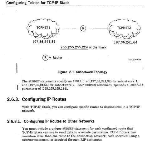
Directory ... 3-15 SUBNET - Defining TCP/1P Netvvork Connections and
Static Routes ... 3-17
Section 4.
Controlling TCP-IP Stack Operation
Summary of NMS Commands for TCP-IP
Stack . . . 4-1
D!SPLA.Y=ARP - Disp!ay ARP Address Mapping ... 4-3 DISPLAY=IP - Display IP Status ... 4-5 DISPLAY=RIPNBR - Display RIP Neighbors ... 4-7 DISPLAY=ROUTE - Display IP Routing Tables ... 4-9 DISPLAY=SAT - Display Source Address Table ... 4-11 DISPLAY= TCP - Display Active TCP Connections ... 4-13 DISPLAY=HELP - Displays Online Help Text ... 4-15 KILL=ARP - Delete ARP Address Mapping ... 4-17 KILL=RIPNBR - Remove an RIP Neighbor ... 4-19 KILL= TCP - Terminate a TCP Connection ... 4-21 MODIFY =ROUTE - Modify an IP Routing Table Entry .... 4-23 PING - Sends ICMP Echo Request ... 4-25 SNAP=IP - Turn On IP Traces ... 4-27 SNAP= TCPTB - Turn On Transport Bridge Traces ... 4-31 SNAP= TCPTS - Turn On Transport Service Traces ... 4-33 SNOF=IP - Turn Off IP Traces ... 4-37 SNOF= TCPTB - Turn Off Transport Bridge Traces ... 4-39 SNOF= TCPTS - Turn Off Transport Service Traces .... 4-41
Appendix A. Configuration Examples
A.!, A.I.I. A.I.2. A.1.3. A.1A. A.I.5.
Telcon DNS Configurations . . . A-I
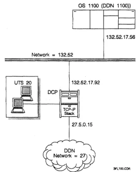
Configuring the DCP as an IP Rbuter
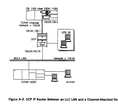
Between a LLC LAN and the DDN ... A-2 Configuring a DCP IP Router Between an
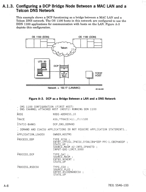
LLC LAN and a Channel-Attached Host ... A-5 Configuring a DCP Bridge Node Between
a MAC LAN and a Telcon DNS
Network ... A-8 Configuring a DCP Bridge Node Between
Contents
A.2. Telcon TSjTN Configurations ... A-20 A.2.1. Configuring a DCP Bridge Node Between
the DDN and a Channel-Attached Host ... A-20 A.2.2. Configuring a DCP Bridge Between the
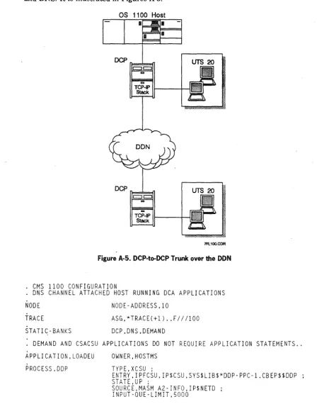
DDN and a TS/TN Network ... A-24 A.2.3. Configuring a DCP to Link DCA
Termination Systems Across the DDN ... A-28
A.3. Configuring the DCP as an IP Router Between an 802.3 LAN and an FDDI
LAN ... A-32
Appendix B. TCP-IP Stack Configuration Concepts
B.l. B.1.1. B.1.2: B.1.3. B.1.4. B.1.5. B.1.6. B.1. 7. B.2. B.2.1. B.2.1.1. B.2.2. B.2.2.1. B.2.2.2. B.2.3. B.2.3.1. B.2.3.2. B.2.3.3. B.2.4. B.2.4.1.
TCPjlP Development ... 8-1
The DoD Communications Model ... B-2 What is a Protocol? ... 8-3 What is an Internetwork? ... 8-4 What is the Defense Data Network
(DDN)? ... B-4 Why Implement TCP j1P? ... 8-5 TCP;1P Communications Architecture ... 8-5 Internet Protocol Development ... B-6
TCP jlP Functional Overview ... 8-7 Process/Application Layer ... 8-7
Application Services Available
through the Internet ... 8-8 Transport (Host-to-Host) Layer ... 8-9
Transmission Control Protocol
(TCP) ... 8-9 User Datagram Protocol (UDP) ... 8-10 Internet Layer ... 8-11 Internet Protocol (lP) ... B-ll Internet Control Message Protocol
(lCMP) ... 8-13 Address Resolution Protocol (ARP) ... B-13 Network Access Layer ... 8-14
WANs: CCID Recommendation
Contents
B.S.
B.6.
B.7.
B.S.
B.8.l. B.8.2. B.8.3. B.8.3.1. B.8.3.2. B.8.4. B.8.5. B.8.6.
TCP-IP Stack Nonstandard TCP Port
Numbers ... B-19
Boundary Nodes between Subnetted
Networks . ... B-19
Host Name Tables ... B-19
TCP-IP Stack Routing Concepts ... B-20
IP Routing ... . . B-20 Default IP Gateways ... B-21 Routing Information Protocol (RIP) ... B-21 Advantages of RIP ... B-21 Disadvantages of RIP ... B-21 Dynamic Neighbor Discovery ... B-22 Autonomous Systems ... B-22 Network Bridging ... B-23
Glossary ...
1Bibliography . . . ..
1General Index ...
1Figures
1-1. 2-1. 2-2.
2-3.
A-I.
A-2. A-3. A-4. A-5. A-6.
A-7.
A-8. A-g.
B-1.
B-2. B-3.
Tables
1-1. Obsolete TCP-IP Stack Configuration Parameters ... , " " ' , " ... 1-5
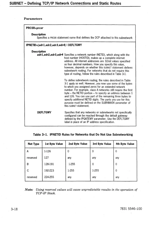
3-1. IPNETID Rules for Networks that Do Not Use Subnetworking ... 3-18
Section 1
Introduction
various subnetworks. This section introduces the TCP-IP Stack program product. It provides the following:
• A description of enhancements for TCP-IP Stack level 2R2 • An overview of the product capabilities
• A list of TCP-IP Stack restrictions
1.1. Enhancements for Level 2R2
This subsection describes the enhancements TCP-IP Stack level 2R2 provides. These include the following:
Component Feature
IP Support new intelligent line modules OLMs)
Eliminate SAP and DLCUNiT statements
Provide interface information with message trace
Enhance bi-directional message trace capability
Implement LENGTH parameter to shorten traced messages
Aiiow trace parameters to be modified while the trace is operational
Introduction
Component Feature
ETNTNET Supports the Terminal Type Option, Terminal Type Subnegotiation, and the End-of-Record (EOR) option.
Support Terminal Type UNISYS-TD830-ASCII
PING Send ICMP Echo requests
1.1.1. Support New IlMs
Internet Protocol (IP) uses configured network and link layer service providers to send datagrams to their destination. The network and link layer service providers can be DCP X.25 Packet-Switched Communication Services (PSCS), Dynamic Network Services (DNS, Telcon's Distributed Communications Architecture backbone), DCP LAN Platform, or a host channel. Support of the new LAN ILMs is added with this release, and coexists with support of the existing DCP LAN Platform.
The following is a description of the ILMs :
LAN Module Capability
802.31LM This ILM is a follow-on product for the 802.3 line module (LM). Both the 802.3 ILM and the 802.3 LM are supported beginning with release 2R2.
FDDIILM This ILM supports the Fiber Distributed Data Interface (FDDI) physical interface standards.
1.1.2. Eliminate SAP and DlCUNIT Statements
You no longer need to use the SAP and DLCUNIT statements when configuring a subnetwork. Without those statements, TCP-IP dynamically attaches to the LAN line module or ILM. Eliminating the need to configure the SAP and DLCUNIT statements is expected to improve the ease with which TCP-IP can be configured. When subnetworks are configured using the SAP and DLCUNIT statements, TCP-IP functions as before_ IP generates a CENLOG indicating that the use of SAP and DLCUNIT statements is obsolete.
Introduction
1.1.3. Provide Interface Information
witb
Message Trace
When tracing messages at the Network Service Provider (NSP) interface, IP specifies the associated interface with the traced message. The information is used when decoding the traced messages.
1.1.4. Enhance Bi-directional Message Trace Capability
When you are conducting a message trace, the SRC and DEST parameters are interpreted as exchangeable when the parameter DIR is set to BOTH. The former convention of tracing messages in both directions whenSRC and DEST are identical is retained.
1.1.5. Implement LENGTH Parameter to Shorten Traced
Messages
The LENGTH parameter specifies the maximum number of bytes copied for each message. When the message is displayed, the string "MESSAGE DATA WAS
TRUNCATED" is appended to the end of the display if the traced message was truncated.
1.1.6. Modify Trace Parameters Without Stopping the Trace
You can enter the command TCP SNAP even for an active trace. The FI LE and REUSE parameters cannot be modified for an active trace.
You can activate traces from only one NMS console at a time. If a second NMS console attempts to activate traces when traces are already active, the command is rejected with the message "TRACE ALREADY ACT! VE".
1.1.7. Provide Local Addresses With IP Status Information
1.1.9. Add Circular Save File Capability to Message Trace
Command (REUSE)
This feature allows traced messages to be saved continuously, reusing the message
trace save files when the last one is full.
1.1.10.
1.1.11.
1.1.12.
The parameter REUS E specifies the number of save files to use while saving traced
messages. The file names are generated by trw..lncating the specified name to no
more than six characters, and appending a two-digit sequence number to the end
of the name, starting with 00 up to the maximum number specified by the REUSE
parameter (the parameter value minus one).
When the current save file is full, TCPIIP closes it, and opens the next one. When
TCP-IP traces messages without reusing the trace files, it terminates message
tracing either when the end of the file is reached, or when the command TCP
SNOF=IP is received.
Update Display of SUBNET and IPADR Information for
LIST commands
The NMS LIST command displays all fields of the SUBNET and IPADR configuration
statements.
Support Terminal Type UNISYS-TD830-ASCII
Server TELNET always requests the tenninal type. If server TELNET receives the terminal type UNISYS-TD830 or UNISYS-TD830-ASCII, server TELNET negotiates the end-of-record (EaR) option.
Implement EOR
)
Introduction
1.2. Obsolete Configuration Parameters
In addition to the configuration changes listed in the previous section, the parameters listed in the following table are no longer used. If used with this release of the TCP-IP Stack program product, they may not produce error messages. However, their use may produce error messages in later releases of TCP-IP Stack.
Table 1-1. Obsolete Tep-Ip Stack Configuiation Paiameteis
Statement Parameters
EU
TCPPORT
DELAY
THRUPUT
RELIABLE
eOMPAR
HREST
TeC
PRECEDNS
1.3. TCP-IPStack Capabilities Overview
TCP-IP also provides additional capabilities. This subsection describes them.
1.3.1. Supported Network Connections
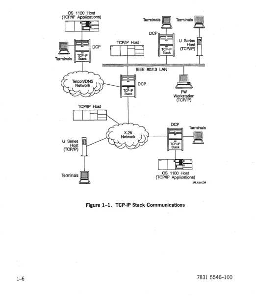
The TCP-IP Stack program product supports IP communications across the
followi.ng:
Introduction
• Unisys DNS networks
• as
llOO-to-DCP host channels. In addition, TCP-IP Stack enables communication between DCA and TCP/IP networks. Figure 1-1 depicts these connections.
OS 1100 Host (TCP/IP Applications)
Terminals
c::Jc::J
'" DCP
\I--:",~I
TCP-IP
Stack
TCP/IP Host
U Series Host (TCP/IP)
TCP/IP Host
Terminals
DCPIl===::k=fl
c::Jc::J
co co
TCP-IP Stack
r
Irs
... ..1 ... ..1 ... .1.. ... .
IEEE 802.3 LAN
c::Jc::J
co
-~I="!!'!co~1 DCP TCP-IP
Stack PW
Workstation (TCP/IP)
DCP
~
co
TCP-IP Stack
Terminals
OS 1100 Host (TCP/IP A.pplications)
2FL100.COR
Introduction
1.3.2. Protocols Implemented
The TCP-IP Stack implements the following protocols:
Protocol Deftned as: Description
TELNET MIL-STD 1782 This protocol is used in the DDN environment. Capabilities terminal and RFC 854 include User TELNET, which provides terminals in the DCA protocols network with access to foreign hostappiications in a TCPjiP
network environment, and Server TELNET, which provides terminals in a TCP liP network environment with access to
as
1100 host applications.Transmission MIL-STD 1778 This protocol provides connections with error detection, control and RFCs 793 positive acknowledgement with retransmission, sequence protocol (TCP) and 1122 numbering, multiplexing, and flow control.
Internet MIL-STD 1777 This protocol performs datagram assembly/disassembly, protocol (IP) and RFCs 791 datagram routing, and internet addressing functions. The IP
and 1122 module also provides an interface to lower layer protocols implemented by other program products such as X.25 PSCS and LAN Platform.
Internet RFCs 792 and ICMP is a sublayer protocol within IP. This implementation control 1122 generates error messages to be transported to other hosts in message response to error conditions.
protocol (lCMP)
Address RFCs 826 and ARP works in combination with !P to route data to
resolution 1122 LAN-connected hosts. ARP maps internet addresses used by protocol (ARP) IP to physical addresses used by the LAN subnetwork
protocol.
Routing RFC 1058. This is one of the protocols used between routers to update information their IP routing tables.
protocol (RIP)
User RFCs 768 and This implementation provides a connection less datagram datagram 1122 transport service to upper layer protocols in the
Introduction
Protocol Defined as: Description
Routing RFC 1058. This is one of the protocols used between routers to update information their IP routing tables.
protocol (RIP)
User RFCs 768 and This implementation provides a connectionless datagram datagram 1122 transport service to upper layer protocols in the
protocol (UDP) process/application layer. It does not guarantee datagram
delivery. TCP~P Stack uses UDP exclusively to support RIP. UDP provides a data checksum service for data integrity error detection. UDP follows the same port addressing and multiplexing rules as TCP.
Domain Name RFCs 1034 This implementation provides a domain name resolver, System and 1035 allowing you to specify a host by name rather than by Internet protocol address.
Subnetwork RFC 1042 This protocol acts as an intermediate protocol between access internetwork and data link protocols.
protocol (SNAP)
1.3.3. Access to DDN Applications
TCP-IP Stack provides two methods to access the OS 1100 DDN 1100 applications. If host-based TCPIIP is configured on the OS 1100 host, the two products
communicate directly, using TCPIIP protocols. Otherwise, host services
(a session relay module in the TCP-IP Stack) contains a module that provides a bridge between the DCA protocol stack and the DDN 1100 applications.
Protocol Description
File transfer FTP is a file-handling service conforming to MIL-STD 1780. With terminal protocol (FTP) commands, subscribers can use FTP to store, retrieve, transfer, or delete service files on the local host or on a remote host.
Simple mail SMTP is an electronic mail handling service conforming to MIL-STD 1781. transfer With terminal commands, subscribers can use SMTP to create, send, and protocol receive mail messages in an environment that includes users on the local (SMTP) service host or on remote hosts in the network.
COBOL This interface for user-written COBOL programs provides program-call program access to the FTP and SMTP services. It also provides program-to-program interface communications with peer processes on the local host or remote hosts in
)
Introduction
1.4. TCP-IP Stack Restrictions
1.4.1. Hardware Related
TCP-IP 2R2 does not perform to its fullest ability on DCPs with less than two megabytes of RAM.
1.4.2. Interoperability
No restrictions.
1.4.3. Compatibility
TCP-IP 2R2 is compatible with all software and hardware included in CD5R3 and Open Systems Products Release 4.
TCP-IP Stack configurations for logical link control (LLC) Type 1 and 802.3 media access control (MAC) LAN attachments on the same LAN ILM are mutually exclusive. All peer LAN stations must use the same link layer protocol for TCP/IP communications.
1.5. Enhancements
for
Level
2R2B
Level 2R2B includes the following enhancements: • DCA session establishment over TCPIIP
A new component, TCPrS, implements RFC 1006, allowing you to establish DCA sessions between DCA host systems (such as an OS2200 host or U Series hosts running Information Services) or between terminals and DCA host systems over a TCPIIP network.
• Token ring (802.5) LAN support
Section 2
Configuring Telcon for TCP-IP Stack
This section describes how to configure Telcon to run TCP-IP Stack program product software. This section does not describe how to configure a complete Telcon system. Because Telcon configuration statements apply to a wide range of communications purposes and configurations, this section describes only how to configure the following communications capabilities provided by the TCP-IP Stack software.
• The various LAN attachments available to TCPIIP on the DCP
This subsection describes TCP-IP Stack configuration requirements for a
typical attachment to a LAN LM or an ILM-40 LAN line module (models EN
or FD).
• Attachment to an X.25 public data network (PDN) and Defense Data Network
(DDN) X.25 subnetwork
This subsection describes the X.25 Packet-Switched Communications Software (PSCS) program product that works with TCP-IP Stack to support TCPIIP communications over any subnetwork based on CCITT X.25 protocols. You can configure X.25 PSCS to provide proper communications services for either DDN (Internet) subnetworks or for a wide range ofX.25 PDNs.
• Configuring a host channel as a TCPIIP subnetwork
This subsection describes how you can configure TCP-IP Stack to use TCPIIP communications across a host channel between a DCP and an OS 1100 host. TCP-IP Stack interfaces with a host channel by configuring it as a TCPIIP subnetwork type, over which it transmits and receives IP datagrams.
• Configuring IP Gateway nodes and routing functions
Configuring Te!con for
TCP~!PStack
• Configuring network bridge nodes
This subsection describes how TCP-IP Stack allows you to configure a DCP to
function as a network bridge node between a TCPIIP network and a Telcon
network that uses a different network layer routing protocol.
• Configuring host names
This subsection explains how DCP TCP-IP Stack can associate a name (such as HOSTl) with a unique IP address.
Before TCP-IP Stack and supporting program products are installed, define your Telcon network using configuration statements that are unique to each program product in addition to standard and modified Telcon configuration statements.
2.1. Before You Begin
2.1.1. Telcon Configuration Statement Reference Information
Section 3 provides complete reference information on unique TCP-IP Stack configuration statements. For standard or modified Telcon configuration statements, only the parameters related to TCP-IP Stack configurations are
explained in this manual. Refer to the following manuals for complete descriptions
of Telcon configuration statements and information on creating a Telcon configuration source file:
• Telcon Configuration Guide (7831 5678)
• Telcon Configuration Reference Manual (7831 5686)
The following manuals provide detailed information on configuration statements and configuration requirements for the program products used with TCP-IP Stack:
• DCP Series LAN Products Configuration and Operations Guide (78315512)
• DCP Series X.25 Packet-Switched Communications Software (PSCS)
Configuration and Operations Guide (7831 5470)
2.1.2. DCPjOS Workstations
Each DCP in your network must have an associated DCP/OS workstation. There
are two kinds of DeP/OS workstations: direct-connect and virtual.
• Direct-connect workstations are connected to DCP ports owned by DCP/OS.
Configuring Telcon for TCP-IP Stack
• Virtual workstations are terminals in the Telcon configuration that are capable of performing most of the functions of a direct-connect workstation, but are not operable unless Telcon is operating.
The Telcon Configuration Guide (7831 5678) describes both types of workstations
more funy.
You can have an operating direct-connect workstation before Telcon is installed. The workstation must be a UNISCOPE® terminal connected to a medium-speed, single-line line module. The workstation can be on any of the first 32 ports of the DCP.
The DCP/OS boot element, located on the diskette you insert in the DCP disk drive, automatically enables a direct-connect workstation. The DCP/OS boot element scans the ports until it finds a terminal that satisfies the criteria for a workstation. Alternatively, you can use the DCP/OS utility MONFIG to specify the workstation port or ports by making entries in the DCP physical device table (PDT). The DCP/OS Operations Reference Manual (7831 5702) tells how to use
MONFIG.
2.2. Telcon Statements that Define TCP-IP Stack
When you add TCP-IP Stack to a Telcon configuration, use the following ) configuration statements to define TCP-IP Stack communications capabilities.
2.2.1. TCP-IP Stack Configuration Statements
The following configuration statements are used to configure TCP-IP Stack software:
ADDRESS Description
Can be used to associate a configuration name with an IP address. The name of the statement can then be used in other statements as a value for a destination parameter.
Configuring Telcon for TCP-IP Stack
IPADR
Description
Assigns IP addresses and associates them with DCA endpoints allowing TCP~P Stack to function as a network bridge node between TCP;1P and DCA networks.
Note: This statement can also be used to create host name directory entries. NSP.1 (optional)
Description
Identifies entries in the host name directory and maps an IP address to a locally specified host name.
NSS (optional)
Description
Defines the operational characteristics of the host name directory. Required if you are using the domain name system resolver.
SUBNET
Description
Defines the characteristics of subnetworks that support TCP /lP communications.
XEU
Description
Configures the following:
• access to the Telnet user application • access to OS2200 DDN applications
• access to DCA applications over a TCP /lP transport
The IPADR, NSM, NSS, and SUBNET statements are unique to the TCP-IP Stack
program product. The ADDRESS, EU and XEU statements are Telcon configuration
Confi&urin& Teicon for TCP-iP Stack
2.2.2. Configuration Statements for LAN Attachments
The following configuration statements are required to configure LAN Platform software to support TCP-IP Stack:
ILC~
..,eICiiptioii
Specifies the line protocol handler for LAN intelligent line modules.
LINE
Description
STA specijies the physical LAN station address (subnetwork point of attachment, or SNPA) for the LAN line module or ILM 40 line module.
DClUNIT (optional)
Description
HLETYPE specifies attachments for IP or ARP. On LLC (802.2) networks ARP does not reQUire a separate attachment.
Starting with release 2R2, this statement is optional.
SAP (optional)
Description
RSHLE refers to the DLCUNIT statement name. If this is a MAC LAN attachment, the parameter ILMIF spedies the interface type !LMM_<\C, the parameter SAPOPT specifies the
TCP~P Stack interface option IPARP, and the parameter LSAP specifies either IPTYPE or ARPTYPE, depending on which attachment is being specified.
Configuring Teicon for TCP-iP Stack
2.2.3. Configuration Statements for X.25 Attachments
The following configuration statements are required to configure )(25 PSCS
software to support TCP-IP Stack:
I
LCLASSDescription
Specifies the line protocol handler for X.25 line modules (X25PKT).
UHE
Description
Identifies the specific X.25 line supporting the attachment.
PDNGRP
Description
Identifies packet~evel protocol (PLP) and interface options for the Tep;1p X.25 attachment.
X25DEF
Description
Identifies unique characteristics of the attached PDN or DDN X.25 network.
)
Configuring Talcon for TCP-IP Stack
2.2.4. Configuration Statements for Host Channel Attachments
The following Telcon configuration statements are required to configure TCPIIP communications over a channel connection to an
as
1100 host:CHANNEL
Description
Defines a channel between an OS 1100 host and the local DCP.
DCATS
Description
Required for the host channel in TSjTN configurations.
TRUNK
Description
Required to configure the host channel to use DNS network layer protocol (the host is configured as a DNS node).
TCP-IP will not initialize the host channel as the only user of the channel. Therefore, even if only TCP-IP traffic is expected on the channel, either a DeATS
Configuring Telcon for TCP-IP Stack
2.3. Configuring TCP-IP Stack Attachments to LAN
Subnetworks
The LAN attachments work with TCP-IP Stack to support TCP/IP communications over LAN subnetworks. TCP-IP Stack can use one of the following LAN
attachments:
.. 802.2 logical link control (LLC) type 1 .. 802.3 media access control (MAC) .. 802.5 token ring
.. FDDI
TCP-IP Stack implements the subnetwork access protocol (SNAP) to provide an OSI conformable attachment or an LLC type 1. Alternatively, internet protocol (IP) can interface directly with the MAC link layer service.
Because of different interface requirements, each of these LAN link layer services has different configuration requirements. You must configure TCP-IP Stack to use the same link layer service as the other TCP/IP stations on the LAN.
2.3.1. LAN Attachment
To configure TCP-IP Stack for a LAN attachment, include the following configuration statements in your configuration file:
Statement Description Required Parameters Additional Information
PRCSR Identifies the DCP as a processor to other Telcon entities.
NETADR Identifies this The NETADR statement assigns a DCP as a DNS DNS node number to the DCP. or node.
DCPTS Identifies a DCP The DCPTS statement associates termination the DCP termination system with system on this a related PRCSR statement. DCP.
LCLASS Defines the LAN LPH=ILML, or LCLASS defines the line protocol line class. =(lLML,'ENET$') handler (LPH) for the LAN line
Configuring Telcon for TCP-IP Stack
Statement Description Required Parameters Additional Information
LINE Identifies the PRCSR Name of the related PRCSR
specific LAN line statement. supporting the
attachment. CLASS Name of the LAN related LCLASS statement.
ADR PPID of the LAN line module.
STA Six-octet (12 hexadecimal digit) LAN station address of the line module.
EU Defines TCP~P PRCSR Name of the related PRCSR
Stack as an end statement.
user.
TYPE=TCPIP TCP~P Stack does not initialize properly without a TCPIP end user statement.
SUBNET Defines the LAN PRCSR Name of the related PRCSR
as a TCPj1P statement. subnetwork.
TYPE=LANLLC l1'PE defines the type of LAN TYPE=LAN. configured as a TCPj1P TYPE=IPFDDI subnetwork.
TYPE=IPTR
IPNETID The network number (the IP address or subnetwork number) of this LAN subnetwork.
LINE Name of the LAN-related LINE
statement. This identifies the referenced line as the physical interface to the LAN subnetwork.
IPADR Assigns an IP PRCSR Name of the related PRCSR
Configuring Telcon for TCP-IP Stack
Example 1
The following example configures TCP-IP stack for LANILLC using the LAN platform.
**
Processor Definition*
DCPl PRCI
*
NETADR
PRCSR NA=l NA=l
** LAN-Reiated Statements
*
LANLLCLNPIOB
* *
LCLASS
LINE LPH=ILML PRCSR=PRCl.CLASS=LANLLC.ADR=X'OB'. ;
STA=X'08000BOC360B'
** TCP-IP Stack Statements
*
EUTCPIP EU
SNLLCPl SUBNET
IPPIHI IPADR
Example 2
PRCSR=PRCl,TYPE=TCPIP
PRCSR=PRCl,TYPE=LANLLC.LINE=LNPlOB,; IPNETID=(208,17.198)
PRCSR=PRCl,DCAEP=DCPl. ;
IPADDRl=(208,17.198.217,LOCAL)
The following example configures TCP-IP Stack for a basic MAC LAN attachment using the LAN line module.
**
Processor Definition*
HOSTlPRCI *
NETADR
PRCSR NA=l NA=l
** LAN-Related Statements
* LANLLC
LNPIOB LCLASS LINE LPH=ILML PRCSR=PRCl,CLASS=LANLLC,ADR=X'OB',;
STA=X'08000BOC360B'
*
**
TCP-IP Stack Statements*
EUTCPIP EU
SNLLCPl SUBNET
IPPIHI IPADR
Example 3
PRCSR=PRCl,TYPE=TCPIP
PRCSR=PRCl,TYPE=LAN,LINE=LNPlOB,; IPNETID=(208,17,198)
PRCSR=PRCl,DCAEP=HOSTl, ; IPADDRl=(208,17,198,217,LOCAL)
The following example configures TCP-IP Stack for LAN LLC, using the LAN platform. LANLC LANLN LANSN LCLASS LI NE SUBNET LPH=I LML
... ,CLASS=LANLC, .. .
)
Configuring Talcon for
TCP~IPStack
Example 4
The following example configures TCP-IP Stack for LAN, using the ILM40-EN line module. LANLC LAN LN LANSN Example 5 LCLASS LI NE SUBNET
LPH=(I LML •• EN ET$' ) ...• CLASS=LANLC •... .•.. TYPE=LAN •..•
The following example configures TCP-IP Stack for LAN LLC, using the ILM40-EN line module.
LANLC LANLN LANSN Example 6 LCLASS LI NE SUBNET LPH=(ILML,'ENET$') ...• C LASS=LAN LC •... ...• TYPE=LANLLC •...
The following example configures TCP-IP Stack for FDDI, using the ILM40-FD line module. FDDILC FDDILN FDDISN Example 7 LCLASS LI NE SUBNET
LPH=( I LML •• FDDl$' ) ..•• CLASS=FDDILC •... .•.• TYPE=IPFDDI, •..
The following example configures TCP-IP Stack for a token ring LAN, using the ILM40-TR line module.
LANTR LANLN TRSN LC LASS LI NE SUBNET
LPH=(ILML. 'TRNG$') .... CLASS~LANTR, .. . ... ,TYPE=IPTR, .. .
2.4. Configuring TCp .. IP Stack Attachments to
X.25 Subnetworks
Confiiurini Telcon for TCP-IP Stack
2.4.1. Generic X.25 PDN Attachment
To configure TCP-IP Stack for a generic X.25 PDN attachment, include the following configuration statements in your configuration file:
Required
Statement Description Parameters Additional Information
PRCSR Identifies the DCP as a processor to other Telcon entities.
NETADR Identifies this DCP as a DNS The NETADR statement assigns node. a DNS node number to the
or DCP.
r"\f"nTt' Identifies a DCP termination
The DCPTS statement
LJ"rlv
system on this DCP. associates the DCP termination system with a related PRCSR statement.
X25DEF Identifies characteristics of NETWORK Name of the PON (from the the specific PDN to which list of PON labels defined for this DCP is attached. PSCS
LCLASS Defines the X.25 line class. LPH=X25PKT X25PKT defines the line protocol handler (LPH) for X.25 lines.
PDNGRP Identifies X.25 packet~evel PDNGRP Name of the related PRCSR
protocol (PLP) attributes statement. and other interface options
associated with this X25DEF Name of the related X25DEF attachment. statement.
VCGRP Range of logical channel numbers assigned as virtual circuits (Ves), and the type of virtual circuit used for this attachment.
LINE Identifies the specific X.25 PDNGRP Name of the related PDNGRP
line supporting the statement. attachment.
CLASS Name of the X.25-related
LCLASS statement.
Configuring Telcon for TCP-IP Stack
)
Required
Statement Description Parameters Additional Information
EU Defines TCP~P Stack as an PRCSR Name of the related PRCSR
end user. statement.
TYPE=TCPIP TCP~P Stack will not initialize properly without a TCPIP end
user statement.
SUBNET Defines the X.25 PDN as a PRCSR Name of the related PRCSR
TCP;1P subnetwork. statement.
TYPE=IPPDN IPPDN defines the X.25 PDN as a TCP;1P subnetwork.
IPt\II:"Tln
II I 'tL-I IL.I The netvvork numbei (the IP
address) of this X.25 subnetwork.
LINE Name of the X.25-related LINE
statement (for single~ink
or attachments only).
\ PDNGRP Name of the related PDNGRP
) statement (for multilink or
single~ink attachments).
This identifies the referenced
LINE or PDNGRP as the physical
interface to the X.25 subnetwork. If the X.25 attachment supports multilink procedures, you must specify only the PDNGRP parameter. You must not specify individual lines of a multilink attachment. The PDNGRP
parameter \"Jorks for either
Configuring Telcon for TCP-!P Stack
Required
Statement Description Parameters Additional Information
IPADR Assigns an IP address to PRCSR Name of the related PRCSR
the DCP X.25 attachment. statement.
DCAEP Name of the NETADR or DCPTS
statement that identifies this DCP.
IPADDRI or The IP address of this X.25 IPADDR2 attachment (must be flagged
LocAL).
IPADR Specifies an IP address for PRCSR Name of the related PRCSR
each remote TCP;1P host statement.
vv'ith vvhich you vvant to
communicate across the IPADDRI or The IP address of the remote X.25 network and pairs that IPADDR2 TCP;1P host (must not be address to a DTE address. flagged LOCAL).
Example
This example configures an attachment to an X.25 network, network number 17. The DCP's address is 17.0.0.5, and a TCP-IP host with address 17.0.0.6 is reachable by DTE address 21601004647.
** Processor Definition
*
DCPl PRCl
*
NETADR
PRCSR NA=l NA=l
** X.25 PON Definition
*
X25DFTEI X25DEF PGPPI TEl PDNGRP
X2596 LCLASS LNP1l3 LINE *
N ETWORK=TELEN ET
PRCSR-PRCI. VCGRP-( 20.30). ; X25DEF=X25DFTEI
LPH=X25PKT
PDNGRP=PGPITEl.CLASS=X2596.ADR=13 ** TCP-IP Stack Definition
*
EUTCP EU SNPDNPl SUBNET
I PPIHl I PADR I PPIH2 I PADR
PRCSR=PRCl,TYPE=TCPIP PRCSR=PRCI,TYPE=IPPDN, ;
PDNGRP=PGPPITEI,IPNETID=(l7,0,0,O) PRCSR=PRCl,DCAEP=DCPl,;
IPADDRl=(17 ,O.0,5.LOCAl),; PRCSR=PRCl, ;
2.4.2. DDN X.25 (Internet) Attachment
To configure TCP-IP Stack for a DDN )(25 attachment, include the following configuration statements in your configuration file:
Required
Statement Description Parameters Additional Information
PRCSR Identifies the DCP as a processor to other T elcon entities.
NETADR Identifies this DCP as a DNS The NETADR statement assigns node. a DNS node number to the
or DCP.
DCPTS Identifies a DCP termination The DCPTS statement system on this DCP. associates the DCP
termination system with a related PRCSR statement. X25DEF Identifies characteristics of NETWORK This specifically defines the
the specific DON to which characteristics of DON X.25 this DCP is attached. subnetworks in Internet.
LCLASS Defines the X.25 line class. LPH=X25PKT X25PK defines the line protocol handler (LPH) for the X.25 lines.
PDNGRP Identifies X.25 packeNevel PDNGRP Name of the related PRCSR protocol (PLP) attributes statement.
and other interface options
associated with this X25DEF Name of the related X25DEF attachment. statement.
VCGRP Range of logical channel numbers assigned as virtual circuits (YCs), and the type of virtual circuit used for this attachment.
Required
Statement Description Parameters Additional Information
UNE
Identifies the specific X.25PDNGRP
Name of the related PDNGRP line supporting the statement.attachment.
f'11I<;:<;: VIo...r'VV Nama of the X.25..,.elated
LCLASS statement.
ADR PPID of the X.25 line module.
EU Defines TCP~P Stack as an PRCSR Name of the related PRCSR
end user. statement.
TYPE=TCPIP TCP~P Stack wHl not initialize properly without a TCPIP end user statement.
IPADR Assigns an IP address to PRCSR Name of the related PRCSR the DCP X.25 attachment. statement.
DCAEP Name of the NETADR or DCPTS statement that identifies this DCP.
IPADDRI or The IP address of this X.25 IPADDR2 attachment (must be flagged
Required
Statement Description Parameters Additionallnfonnation
SUBNET Defines the X.25 DON as a PRCSR Name of the related PRCSR TCP;1P subnetwork. statement.
TYPE=DDN DON defines the TCP;1P
_'4L __ L. •• __ I . .L _ _ _ _ "'''''''I
:suullt:lwur 1\ lype C:I:S ULJI'i
X.25. Use the label DON only if
connecting to an actual 000 DDN X.25 network. These X.25 networks support a specific DTE addressing scheme that allows an address conversion algorithm to turn an IP address into a DTE address. Whiie this algorithm can be implemented on any private network, it is not. compatible with most X.25 networks DTE
addressing schemes, nor is it compatible with CCITT recommendation X.l21.
In addition to the addressing, the DON X.25 networks use a set of proprietary X.25 facilities. Unless the non'[)DN
'i ' " nAiwnrk r"n i<1nnro
, •. _ - ... - - , . 'b"v ...
them, these facilities may cause problems and prevent completing connections across the network.
IPNETID The network number (the IP address) of this X.25 subnetwork.
)
Configuring Telcon for TCp·IP St::ack
The following tenninology is used exclusively for the DDN address:
Term Fonnat
Network NN
Host or Trunk HH
PSN II
Class A NN,HH,OO,II
Class 8 NN,NN,HH,II
Example
This example illustrates configurations where an X.25 link connects to a DDN network. The TCPIIP network number is 26, the host number is 4, and the PSN trunk is 5.
** Processor Definition
*
DCPl PRCl
*
NETADR
PRCSR NA=l NA=l
** X.25 DDN Definition: *
X25DFDDN X25DEF PGPPIDDN PDNGRP
X2596 LNPl23 *
LCLASS LI NE
NETWORK=DDNX25
Dor<:O=Dorl IIrr..DD=( '<, ~(\ \ • X255EF~X256F55N',
;
'V~ • .JV I • •DTEADR='000000050400' LPH=X25PKT
PDNGRP=PGPIDDN.CLASS=X2596.ADR=23
** TCP-IP Stack Definition: *
EUTCP EU SNPIDDN SUBNET
IPPIDDN IPADR
PRCSR=PRCl.TYPE=TCPIP
PRCSR=PRCl.TYPE=DDN,PDNGRP=PGPPlDDN. ; IPNETID=26
Configuring Telcon for TCP-IP Stack
2.4.3. Configuring Unique X.25 Capabilities
When you configure an X.25 attachment, you must make a number of
configuration choices that depend on the network type and its specific capabilities. The SUBNET and IPADR statements provide some optional parameters to configure
unique X.25 capabilities.
2.4.3.1. Confi&urin& IP-to-DTE Address Pairin&s
For generic X.25 attachments, you must include an additional IPADR statement for
each remote TCPIIP host reachable (across the PDN) through the attachment.
Each IPADR statement that refers to a remote host must include an I PADDR
parameter (not flagged LOCAL) and a DTEADR parameter to associate the DTE
address of a specific remote host with a unique IP address. You can use either IP
address parameter (I PADDRI or I PADDR2).
When you configure an IPADR statement that uses both IP address parameters, the
DTE address of the remote host pairs with the IP address that is not flagged
LOCAL.
If neither IP address is flagged LOCA L, the DTE address pairs with the IP address
specified by parameter I PADDRl. .
Example
This example configures two IP address-DTE address pairs. The first pair is
configured on IPADRI to identifY a specific remote TCPIIP host. This would, for
example, allow terminals to use the TCP-IP Stack User TELNET application to connect to that host across the X.25 network.
The second pair is configured on IPADR2, which configures TRUNKI to bridge the
X.25 network. The I PADDR2 and DTEADR parameters provide the apdressing
information for the DCP at the remote end of the trunk.
IPADRI
I PADR2
IPADR
IPADR
PRCSR=PRCSRl.IPADDRl=(34.24.0.125). ; DTEADR='18010007736'
PRCSR=PRCSRl.DCAEP=TRUNKl. ; I PADDR1=( 34.45.0.32. LOC,t.,L) • ;
2.4.3.2. Configuring X.25 Single-link and Multilink Attachments
The X.25 PSCS program product can implement two types of physical attachments
to an X.25 network:
• Single-link attachments are configured as one line per DTE address (one LINE
statement per PDNGRP statement).
• Multilink attachments are configured as two or more lines per DTE address
(multiple LINE statements per PDNGRP statement).
You must configure a SUBNET statement to identify the X.25 link or links that
TCP-IP Stack uses to attach to the X.25 network. All LINE statements, whether for
single-link or multilink configurations, must refer to a PDNGRP statement.
Therefore, you should use the PDNGRP parameter on the SUBNET statement to
specify all X.25 attachments.
2.4.3.3. Configuring the Number of Virtual Circuits Per Connection
When making a connection to another host across an X.25 network, PSCS establishes a virtual circuit (VC) route across the network. Each VC has a
bandwidth limited by the packet size and window size allowed by the network. IP may try to increase the bandwidth of a given X.25 connection by requesting . additional VCs when PSCS signals that data is backing up on an existing VC.
The drawback of this method is that a host can be limited in the number of VCs it can support simultaneously, either because of software limitations, or because of
its subscribed connection to the X.25 network. Establishing additional
ves
mayuse resources that should remain available for other connections.
You can limit the number of VCs used per connection by specifying a value for the
I PMAXVC parameter on the SUBNET statement. If you do not include the
I
PMAXVCparameter it defaults to zero, indicating that no limit is set.
Example
2.5. Configuring a Host Channel as a TCP jlP
Subnetwork
Although the channel configuration has the same basic requirements as a DNS channel, the related TCP-IP Stack statements and the matching CMS 1100
configuration enable TCPIIP communications over the channel without dependency on DNS protocols. TCP-IP Stack treats the host channel as an entire TCPIIP network.
CMS 1100 software on the host must be configured to use TCPIIP communications over the host channel. CMS 1100 level 7R3 (SB4R5) or a later release is required
to configure TCPIIP communications.
Note: This configuration does not apply to LAN attached hosts. When an
as
1100host is connected to a LAN through a Host LAN Controller (HLC), TCP-IP Stack communicates with the host as with any other TCP lIP host connected to the LAN.
To configure a host channel as a TCPIIP subnetwork, include the following network definition statements in your configuration file:
Required
Statement Description Parameters Additionallnfonnation
PRCSR Identifies this processor as NA=n The variable n represents the
a DNS node to other DNS network address or node T elcon entities. number you assign to this
node. Each node in a Telcon DNS network must have a unique address.
NETADR Assigns a name (label) to a NA=n The variable n represents any
(optional) DNS network address valid DNS hierarchical reachable through this network address for this attachment, such as the T elcon DNS network. It can
DC? itself, a be a subdomain, super channel-attached host, or a cluster, simple cluster, or remote host in the T elcon node address. For DNS DNS network. configurations, multiple TRUNK
Configuring Telcon for TCP-IP Stack
Required
Statement Description Parameters Additional Information
TRUNK Defines the attachment to PRCSR The name of the related PRCSR
the host channel statement for this trunk. For a subnetwork. The host trunk configured over a host channel must be channel, you specify only the configured as a logical name of the attached
trunk. processor.
LSUTYPE=DNS
CHANNEL Configures the physical PPID The DCP port processor channel connection number to which the channel between the DCP and the is connected.
host.
TRUNK The name of the related
TRUNK statement for this channel.
EU Defines TCP~P Stack as an PRCSR Name of the related PRCSR end user. statement.
)
TYPE=TCPI P The TCP~P Stack will notinitialize properly without a
TCPIP end user statement.
SUBNET Defines the channel as a PRCSR .Name of the related PRCSR TCP;1P subnetwork. statement for this DCP.
TYPE=IPCHAN Identifies the host channel as a TCP;1P subnetwork type.
Configuring Telcon for TCP-IP Stack
Required
Statement Description Parameters Additional Information
IPADR Assigns an IP address to PRCSR Name of the related PRCSR
the DCP's host channel statement for this DCP.
attachment.
OCAEP The name of the NETADR
statement that assigns a DNS
network address to this Dep.
I PAOORI The complete IP address
assigned to the host channel attachment. You must include the LO CA L flag on this parameter.
Exampie
This example shows a trunk connected to a CMS 1100. The CMS 1100 is running its own version of TCPIIP. The network number for the channel is 173.53.130. The address of the DCP is 172.53.130.42.
The TRUNK statement sets up a DNS connection over the CHANNEL. Alternatively, a TSTN SESSN can be configured over the CHANNEL. TCP-IP Stack cannot
initialize the CHANNEL by itself. Either TRUNK or SESSN must be used.
**
Host and processor definitions*
OCPl PRCl
*
NETAOR
PRCSR NA=l NA=l
**
ONS host channel definition*
TKCPIHI TRUNK PRCSR=PRCl.LSUTYPE=ONS
CHANHI CHANNEL PPIO=X'OE' ,TRUNK=TKCPIHI
*
** TCP-IP Stack configuration
*
EUTCP EU
SNCHAPI SUBNET
IPPIHI IPAOR
PRCSR=PRCl.TYPE=TCPIP PRCSR=PRCl.TYPE=IPCHAN. ;
IPNETID=(172.53,130),CHANNEL=CHANHl PRCSR=PRCl,OCAEP=OCPl, ;
2.6. Configuring IP Gateway Nodes and Routing
Functions
TCP-IP Stack allows you to configure a DCP to perform IP routing functions within a TCPIIP network. With TCP-IP Stack, you can configure the following IP gateway capab