MAY 1961
RESTRICTED DISTRIBUTION
Univac®
LARC
PROGRAMMING
THE
COMPUTING UNIT
7£y,~
7Isnd
~®Heading 2-1. 2-2. 2-3. 2-4. 2-5. 2-6. 2-7. 2-8. 2-9. 2-10. 2-11. 2-12. 2-13. 2-14. 3-1. 3-2. 3-3. 3-4. 3-5. 3-6. 3-7. 3-8. 3-9. 3-10. 3-11. 3-12.
CONTENTS
TitleSECTION 1. INTRODUCTION
SECTION 2. LOGICAL OPERATION OF THE COMPUTING UNIT
General
. . .
.
·
•·
· · ·
•· ·
•·
The Control Unit.·
·
· · · ·
·
· · · ·
Instruction Registers.
· · ·
•·
Control Counters·
·
•·
•·
·
• • The B Adder.·
·
·
·
·
•·
·
·
Memory Address Decoders.·
·
•·
·
Operation Decoder.·
·
•·
The Arithmetic Unit· ·
·
·
·
·
•·
•·
Fast Registers.· ·
·
·
·
·
·
·
·
·
Addressable Flip-Flops.· ·
•·
•· ·
·
The High-Speed Bus. •·
·
·
·
•·
·
Execution of an Instruction·
· ·
·
·
·
Instruction Overlapping·
·
·
· ·
·
·
·
·
·
Control of Errors, Contingencies, and the Tracing Mode.
·
·
·
·
·
•·
•·
• •·
·
SECTION 3. INSTRUCTION DETAILS
·
.
·
·
·
• •Instruction Format. • •
Index Register Format •
·
.
. . . .
.
· .
.
Operands. • • • • • • • • • • • • • • • • • Floating-Point ArithmeticProgram Conventions • • • •
·
.
Data-Transfer Instructions. • • • • • Fixed-Point Arithmetic Instructions
Unconditional-Transfer-of-Control Instructions. • • • • • • • • • Conditional-Transfer-of-Control
Instructions • • • • • • • • • • • • Extract Instructions. • • • • •• Shift Instructions. • • • • • • • • Index-Register-Modification
Instructions ••
iv Heading 3-13. 3-14. 3-15. 3-16. 3-17. Title
Floating-Point Arithmetic Instructions • • • Conversion Instructions • • • • • • • Visual-Display Instructions • • • • • • •• Flip-Flop Instructions. • • • • • • • • Miscellaneous Instructions • • • • •
SECTION 4. OPERATIONS OF INPUT-OUTPUT EQUIPMENT
4-1. 4-2. 4-3. 4-4. 4-5. 4-6. 5-1. 5-2. 5-3. 5-4. 5-5. 5-6. 5-7. 5-8. 5-9. 5-10. 5-11. 5-12. 5-13. 7-1. 7-2. 7-3. 7-4. 7-5. 7-6.
General
.
. .
·
•·
·
·
·
·
·
· · ·
Data Codes.. ·
·
•·
· ·
Magnetic Drums.
·
·
· ·
·
·
·
·
Magnetic Tapes.
·
•·
· · ·
Line Printer.
· ·
•· ·
· · · ·
·
·
·
·
Electronic Page Recorder.·
· ·
·
·
SECTION 5. OPERATING PROCEDURES
Operator's Stations
·
·
· · ·
·
· ·
Operator's Console·
·
·
· · ·
·
·
Display Panel·
·
·
·
·
·
Controls.·
·
·
·
· · ·
·
Console Keyboard.· · ·
• Console Printer·
·
·
·
•·
·
Paper Tape Handling
· ·
•Tape Preparation
·
•·
Tape Reading
· · ·
·
·
·
·
Program Load Procedures
· ·
•·
·
·
·
• Load Procedure 1·
·
•·
·
·
·
Load Procedure 2· · ·
•·
·
·
Load Procedure 3· · ·
•·
·
· · ·
SECTION 6. INDIRECT ADDRESSING
SECTION 7. CONTINGENCIES, ERRORS, AND TRACING MODES
·
•·
·
·
·
·
· ·
·
·
·
·
·
· ·
·
·
·
·
·
·
·
•· ·
•·
· ·
·
· ·
·
·
•·
·
Introduction. • • • • • • • • • Contingencies • • • • • • •
Contingency Flip-Flops •
·
.
.
.
.
.
Errors. • • • • • • • • • • • • • Error Flip-Flops • • • • Tracing Modes • • • • • • • • • •
Heading C-l. C-2. C-3. C-4. C-5. Figure 2-1. 2-2. 2-3. 2-4. 5-1. 5-2. 6-1. 6-2. 6-3. 6-4. C-l. Title
APPENDIX A. NUMERICAL LIST OF INSTRUCTIONS
APPENDIX B. ADDRESSABLE FLIP-FLOPS IN THE COMPUTING UNIT
APPENDIX C. REMINGTON RAND UNIVAC PROCESSOR PROGRAM
Magnetic Drum Summary Orders. • • • • • • • Magnetic Tape Summary Orders • • • • • • Line Printer Summary Orders • • • • • • Electronic Page Recorder Summary Orders • • Miscellaneous Summary Orders • • • • • • • •
ILLUSTRATIONS
Title
Computing Unit Block Diagram • • • • • • • • Allocation of Time Slots on the High-Speed
Bus • • • • • • • • • • • • •
.
.
.
.
.
.
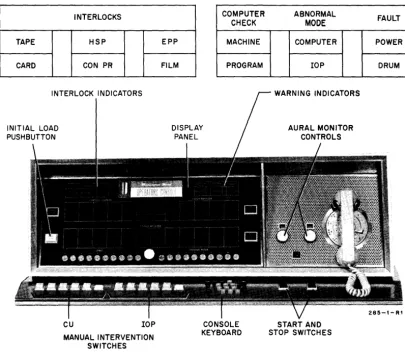
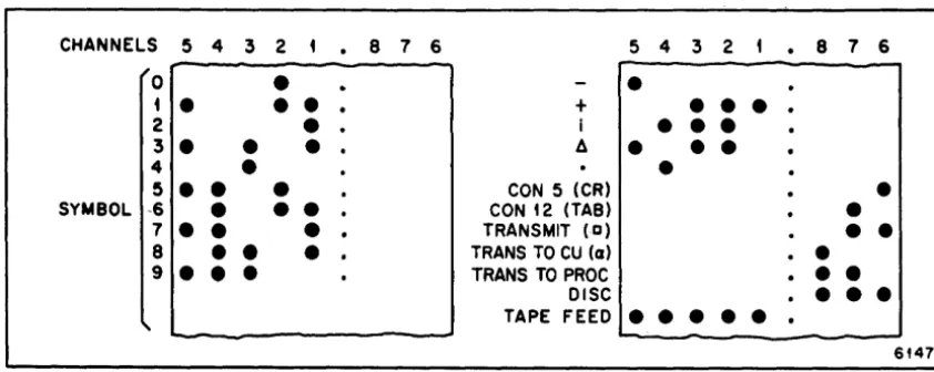
Instruction Overlapping • • • • • • • • • • Sequencing of anUnconditional-Transfer-of-Control Instruction • • • • • • • • Operator's Console. • • • • • • • • • • Tape Symbols. • • • • • • • • • • • • • • • Address Selection in Indirect Addressing •• Example of Classification Tree • • • • • • • Indirect-Address Tree • • • • • • • • • • • Determining Indirect Addressing Sequence •• Summary Order Execution and Filing • • • • •
Table
4-1.
5-1.
6-1. 6-2.
TABLES
Title
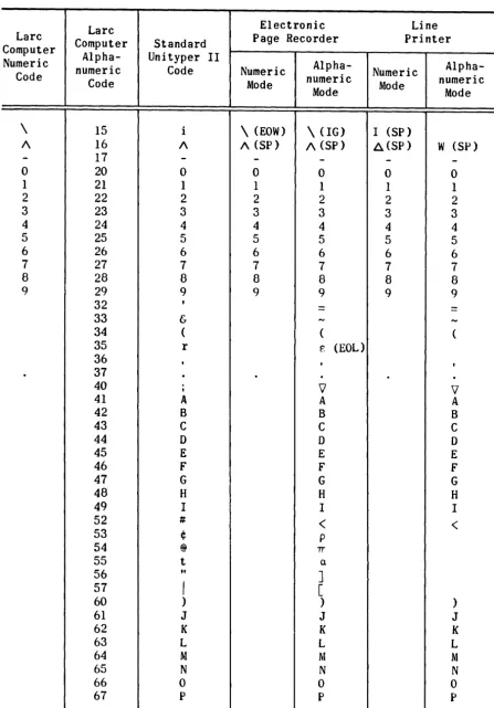
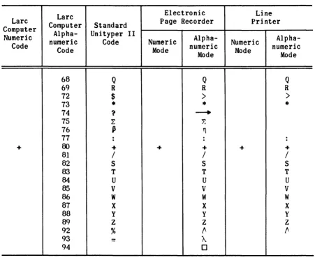
Larc Computer Codes • • • • • • • • • • Console Printer Characters and Actions.
.
.
The Table • • • • • • • • • • • • • • • Storage Locations for Indirect-AddressTree. • • • • •
.
.
. .
.
.
.
. . .
.
7-1. Contents of 02600 After Transfer to 02601Occurs. • • • • • •
.
. .
.
. . .
. .
.
.
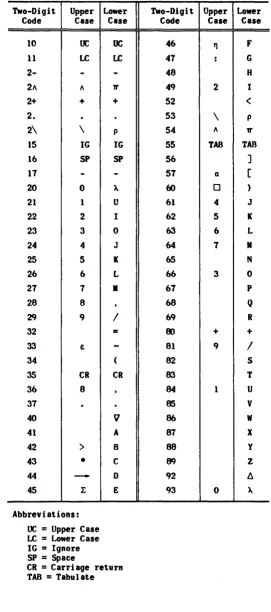
C-l. Alphanumeric Code for the Console Printer •Page
4-4
5-6 6-10 6-10
SECTION 1
INTRODUCTION
The Univac® Larc* Computing System basically comprises two units, the Computing Unit,** and the processor. The Computing Unit is the primary computer; the processor (a secondary computer) handles the input-output operations. The two units are programmed independently, requiring only a minimum of intercommunication.
This programming manual is designed to provide the experienced pro-grammer with the information necessary to write programs for the Larc Com-puting Unit. The publication Univac Larc Programming, The Processor pro-vides similar information for programming the processor. Both manuals assume a familiarity with the essential features of the system. General information is available in the publication Univac Larc System, General Description.
The manual begins by introducing the programmer to the function of the Computing Unit in the system (section 2). This preliminary matter ex-plains how instructions are sequenced, in general how errors and contin-gencies affect a program, and how the various parts of an instruction word are employed.
The main body of the manual (section 3) presents the Computing Unit instruction repertory. The individual instructions are described by class; information that applies in general to instructions in a class is given at the beginning of each class. A condensed list of all the instructions is found in appendix A.
*
Trademark of the Sperry Rand Corporation.**
A Lare system may contain one or two Computing Units. This manualis written for the Lare System, serials land 2, which contains one
Section 4, on input-output operations, describes the numeric and
alphanumeric codes and the input-output equipment including suggestions for the use of each of the devices. The method of communication between pro-cessor and Computing Unit is described in detail.
Operating procedures are discussed in section
5.
The programmer must be familiar with this information in order to instruct the operator during debugging and final runs. Subjects such as program loading, manualinter-vention, visual display, and PQper tape handling are covered in this sec-tion.
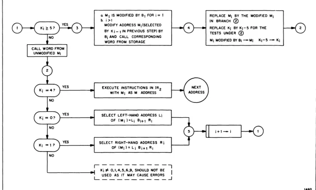
Section 6 consists of a complete discussion of indirect addressing. InCluded are the reasons for using indirect addressing, a description of the method of coding it, and coded examples of its use.
Details of tracing modes, errors, and contingencies are available in section 7. In this section, the addressable flip-flops are discussed at length, with information on the way in which they are set, tested, and re-set. (A complete list of addressable flip-flops is found in appendix B.) Suggestions are made as to procedures which may be followed in the rou-tines handling these operations.
SECTION 2
LOGICAL OPERATION OF THE COMPUTING UNIT
2·1. GENERAL
The Larc computer is an extremely high-speed computing device. Its high speed is obtained in part by using overlapping instructions, that is, the computer does not wait until an instruction has been executed before extracting the next from storage. Consequently, instructions follow each other rather closely through the stages of the control unit. In fact, as many as four instructions may be in the control unit at anyone time.
This overlapping of instructions of course increases the complexity of the computer and imposes certain sequencing restrictions on the program-mer. In some cases by careless use of instructions a programmer may in-crease the running time of his program. In rare instances errors can be caused by failing to observe the restrictions. Section 3 of this manual points out the more obvious restrictions on every individual instruction.
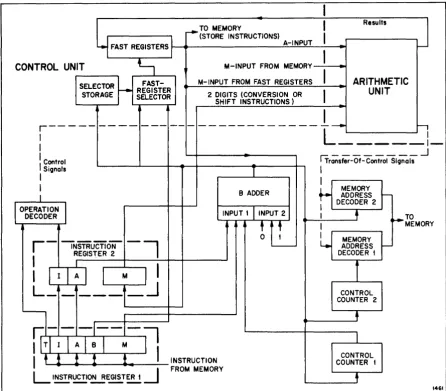
This section presents a simplified description of the Computing Unit control operations. (See figure 2-1 for a block diagram of the major units in the Computing Unit.) Because the main function of the control unit is the sequencing and execution of instructions, each component of this unit is explained and its function is described. A brief outline of the se-quencing of instructions is given and a typical instruction is followed through the various stages of modification, decoding, and execution. The section ends with a brief introduction to the error and contingency rou-tines and the tracing mode.
With this background information the programmer will be able to under-stand more clearly the necessity of precautions in the sequencing of in-structions and in many instances will be able to work out for himself the effect of certain sequences on his program.
Before the programmer can fully understand the remainder of this sec-tion, he must be aware of the structure of the Larc Computing Unit instruc-tion word. Hence, a brief descripinstruc-tion follows. (Further information on this topic will be found in section 3.)
A Larc word consists of 12 characters. A generalized instruction word
is shown as follows:
T II AA BB MMMMM
The T digit, which need not be numeric, is known as the tracing digit. Certain values of this character lead to abnormal operation of the control
unit. In general, the tracing digit will usually be a period, which will cause normal operation. The reader may assume in the discussions that fol-low that the tracing digit is a period unless otherwise stated.
The two I, or instruction, digits determine the operation that is to be carried out. The instruction (operation) code is discussed fully in section 3. In the present section any particular instruction code used will be explained as it appears.
The two A digits specify the address of a fast, or A, register. Fast registers are fast-access, 12-digit storage registers. Besides serving as fast-access storage, they also have some special properties which are ex-plained in section 3. In this section the reader may assume that in any operation one of the operands will be the contents of the fast register specified by the A digits of the instruction.
The M digits of an instruction usually specify a main storage address from which the second operand of many instructions is extracted. The M digits may also specify the number of shifts in a shift instruction or the address to which control is transferred in a transfer-of-control instruc-tion.
The B digits also specify the address of a fast register. In this case the contents of the register are used to modify the
M
address of the instruction. The five least-significant digits of the B fast register are known as the modifiers and are added to the M digits of the instruction to produce the modified address. Any carry produced outside the five least-significant-digit positions is ignored. Hence, an address can be increased or decreased by modification. For example, if the modifier 99999 is added to the address 06500, the modified address will be 06499. Note that ification does not alter the instruction in its storage location; the mod-ification takes place only in the control unit. Note also that the fast registers used in modification are the same fast registers used to hold operands.The general pattern of an arithmetic operation is that an operand from a fast register (A) and an operand from a main storage location (M) enter
the control unit and the result is sent back to the fast register.
This brief explanation of instructions is sufficient to enable the reader to follow the arguments presented in the rest of this section.
2-2. THE CONTROL UNIT
storage and fast registers. to perform a variety of arithmetical and log-ical operations on the operands, and to return the results to storage. Figure 2-1 is, of course. a highly simplified diagram and shows only a few of the many interconnections of the control unit. More complete diagrams are included in the relevant logic manuals.
The individual major components making up the control unit are de-scribed in paragraphs 2-3 through 2-7.
Y
FAST REGISTERS
I
I
ResultsTO MEMORY
~ (STORE INSTRUCTIONS)
I
A-INPUT
I--I
CONTROL UNIT
t-,
M-INPUT FROM MEMORYI
SELECTOR FAST- M-INPUT FROM FAST REGISTERS ARITHMETIC
STORAGE
r---
SELECTOR REGISTER 2 DIGITS (CONVERSION ORI
UNITSHIFT INSTRUCTIONS)
I
r - - - - -- - - -
--- --
- ---~h
I
L - - - l
I
I Control rTr;';-sfer-Of-
ControiSl9na~
..JI Signals
T I
I I
I B ADDER
+---
MEMORYI ADDRESS
I--I DECODER 2
I
OPERATIONI
INPUT'1
INPUT 2DECODER I j TO
btL
I ~MEMOR YI
MEMORY
~r-
-INSTRuCTiON-, ADDRESSI
REGIS1ER 2 DECODER t1
I
I
I
I : I I
M
I
I
L ______
.J
CONTROLCOUNTER 2
•
irTIII AI!i-M-
~
ICONTROL
I t ! !
t
!
INSTRUCTION COUNTER tL
I~~O!!.!~~-.J
FROM MEMORY,
1461
Figure 2-1. Computing Unit Block Diagram
2-3. INSTRUCTION REGISTERS
There are two instruction registers in the Larc system control unit. They are special storage registers which hold instructions while they are
being decoded. All instructions entering the control unit pass through these two registers.
in IRl, its M address is modified
bythe contents of the specified B
re-gister.
Instruction register 2 (IR2) is the final storage register for structions. This register receives the I and A digits from the first in-struction register and also stores the modified M address. After modifica-tion takes place the B digits are no longer required and are not stored in IR2. The instruction is held in IR2 until the final decoding is completed and the necessary information for execution of the instruction has been brought into the control unit.
2-4. CONTROL COUNTERS
A control counter is used to control the extraction of instructions from storage and to ensure that they are extracted in correct sequence. Because of the overlapping operations in the Larc Computing Unit two con-trol counters, numbers 1 and 2, are required. One is used in the normal sequencing of instructions; the other is used when a transfer-of-control instruction is being decoded.
Control counter 1 (Cl) contains the five-digit address of the instruc-tion in IRI. In a normal sequence of instrucinstruc-tions, that is, a sequence containing no transfers of control, the address in Cl is increased by 1
after each instruction has been executed causing the control counter to fetch the next instruction and store it in IRI.
When a transfer-of-control instruction is decoded, the modified
M
ad-dress is sent to control counter 2 (C2). If transfer takes place, the con-tents of Cl and C2 are interchanged so that Cl contains the first address of the new sequence of instructions, and C2 contains the address of the next instruction following the transfer-of-control instruction. If the transfer of control does not take place (C2) and (Cl) are not exchanged. In either case, the contents of C2 remain unaltered until the next transfer-of-control instruction is decoded. Thus, at any stage in a program C2 con-tains the address of the instruction to which control was not transferred during the execution of the previous transfer-of-control instruction. If in instructions 80 and 81, B-modifier increment (or decrement) and trans-fer, no transfer of control takes place, (C2) is advanced to M + 1 before the control unit proceeds to the next instruction.Example:
Storage location 25 contains a test-for-zero instruction.
(00025)
= •
72 01 00 00010The instruction tests the contents of fast register 01. If the con-tents equal zero, control is transferred to storage location 10; if the contents do not equal zero the control unit continues with the next in-struction in sequence, address 00026.
If (01) = 0, then (Cl) and (C2) are interchanged; that is, after the trans-fer of control:
(Cl) = 00010 (C2)
=
00026If (01) ~ 0, then (Cl) and (C2) are unchanged; that is, after the comple-tion of the instruccomple-tion:
(Cl) = 00026 (C2) = 00010
In the first case, the next instruction to be executed will be taken from storage location 10; in the second case it will be taken from storage lo-cation 26.
This explanation of the operation of the control counters is simpli-fied intentionally and is inexact in one or two particulars. For the pro-grammer's use it is entirely sufficient, however.
2-5. THE B ADDER
The B adder is a five-digit parallel adder whose primary function is the B-modification of
M
addresses. The adder also performs many other operations during the fetching, decoding, and execution of an instruction. Taking the execution of a simple instruction as an example. the firstoperation performed by the B adder is the addition of the number 00001 to the five-digit address in Cl. This produces the address of the next in-struction to be brought into IRI.
The B adder is also used to interchange the contents of Cl and C2 after a transfer-of-control instruction, and for various incrementing and decrementing operations.
2-6. MEMORY ADDRESS DECODERS
There are two memory address decoders in a Larc control unit. They are used to decode storage location addresses before fetching words from storage. The memory address decoders in fact partially decode the M ad-dress, selecting the cabinet, the storage unit within the cabinet, and partially selecting the storage location. The decoded information is sent over the address lines to the selected storage unit where the final decod-ing of the storage location takes place.
Memory address decoder 1 (MADl) receives the addresses it is to decode
from control counter 2. These addresses are only decoded and sent to the memory when control signals are received indicating that a conditional transfer of control is to occur.
2-7. OPERATION DECODER
The operation decoder decodes the operation code bits of an instruc-tion in IR2. The decoding process generates control signals which govern the rest of the circuits during the execution of the instruction.
The decoder is also used to decode the tracing-mode digit from IR1. Depending on the character, control signals are generated to signal tracing mode, indirect-addressing mode, or normal operation.
2-8. THE ARITHMETIC UNIT
The arithmetic unit (AU) carries out all the arithmetic and logic operations in the Computing Unit. Before the AU can execute an instruction
it needs operands and information about the operation to be performed. Control information enters the AU before the operands in order to give the unit sufficient time to prepare its circuits. The information derived from the decoding of the operation digits of the instruction, arrives in the form of control signals from the operation decoder.
There are two input channels to the AU for operands. These channels are known as the M-input and the A-input. In general, operands for the first input come from the memory location specified by the M digits of the instruction, whether these refer to a storage location or to a fast re-gister. Operands for the second input come from the fast register speci-fied in the A-digit positions of the instruction word. The two operands arrive at the AU simultaneously.
In shift and conversion instructions no operand is supplied to the M-input channel. Only the two least-significant M digits, after modifica-tion, are used and they specify the number of shifts to be performed or the conversion scale factor. They enter the AU by a special input line from IR2.
The output from the AU may be results which are sent to fast registers or storage locations, or may be control signals which govern transfer-of-control operations. Error and contingency signals are also generated by the AU.
The AU operates independently after it has been supplied with operands and control signals.
2-9. FAST REGISTERS
This unit accepts pairs of digits from the instruction registers or from the B adder and selects the fast register specified. The selector prepares the fast register to acc
7
pt information or to transmit it when the appro-priate control signal is received. In some cases fast-register-result ad-dresses are temporarily stored in a two-digit storage before being sent to the fast-register selector. The two-digit storage is known as the selector storage unit.2-10. ADDRESSABLE FLIP-FLOPS
Flips-flops are one-bit storage devices which, at any time, are in either an on (set) condition or an off (reset) condition. In the Larc com-puting system there are many of these storage devices (not shown in figure 2-1) which are used for a variety of control purposes.
Appendix B to this manual comprises a list of addressable flip-flops in the computing unit, that is, the flip-flops which can be addressed by an instruction. The list also indicates the degree of control the pro-grammer has over the flip-flops, that is, whether he can test, set, or re-set them.
The flip-flops in the Larc system have many functions. Some are sole-ly for the use of the programmer and are entiresole-ly under his control; others are used for indicating errors or contingencies and may only be tested and reset by the programmer. Still others serve as a means of communication between Computing Unit and processor.
2-11. THE HIGH-SPEED BUS
The high-speed bus is a fast-transfer channel between the main storage units and the rest of the system. It is used by the Computing Unit, by the central processor, and by the synchronizers of the various input-output units by way of the processor dispatcher.
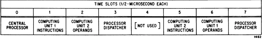
It requires 1/2 microsecond to transfer a word on the high-speed bus. Thus, during every memory cycle (4 microseconds) the bus can handle eight words. These 1/2-microsecond periods, or time slots, are allocated in a special way to the various units using the bus. Figure 2-2 shows how the eight time slots in a 4-microsecond memory cycle are distributed.
TIME SLOTS (112 -MICROSECOND EACH)
0 1 2 3 4 5 6 7
CENTRAL COMPUTING COMPUTING PROCESSOR
[NOT USED]
COMPUTING COMPUTING PROCESSOR
PROCESSOR UNIT t UNIT 2 DISPATCHER UNIT 2 UNIT t DISPATCHER
INSTRUCTIONS OPERANDS INSTRUCTIONS OPERANDS
1462
Figure 2-2. Allocation of Time Slots on the High-Speed Bus
2-12.
EXECUTION OF AN INSTRUCTION
In order to illustrate the over-all operation of the control unit a simple instruction will be traced through the unit. Figure 2-1 shows a simplified block diagram of the control circuits and reference should be made to this figure in following the explanation in the succeeding para-graphs.
It is assumed that initially the address in Cl is 00400, and that storage location 00401 contains the following instruction:
T I A B M
• 01 05 12 00100
and that fast register 12 contains:
000 00 00 00050
The instruction tells the control unit to add the contents of storage lo-cation 00100 (modified by the contents of fast register 12) to the contents of fast register 5 and leave the result in register 5.
First, the contents of Cl (00400) are sent to input 1 of the B adder and the number 00001 is selected for the second input. The output of the B adder is the sum of the two inputs, or 00401, the address of the next
instruction. This address is returned to Cl to be stored until required for selection of the next instruction after 00401. The address is also sent to MAD2 where the cabinet and storage unit containing storage location 00401 are selected. The partially decoded information is sent from the memory address decoder over the address lines to the relevant storage unit.
In the storage unit the final decoding is done and the selected word (00401) is transmitted over the high-speed bus to IR1.
As the instruction digits enter IRI the tracing-mode digit (.) enters the operation decoder and is decoded to signify normal operation. Simul-taneously, the two B digits of the instruction are sent to the fast-register selector, which decodes the digits and selects the correct fast register (register 12). The selector causes the five least-significant digits of the register (00050) to be transmitted to input 2 of the B adder. While the B-register selection takes placel the M digits of the instruction
in IRI (00100) are sent to input 1 of the B adder, and at the same time, the I and the A digits of IRl proceed to IR2.
The operation digits of the instruction in IR2 enter the operation de-coder where signals are generated to direct the remaining stages of the in-struction. In particular, control signals are sent to the AU to prepare it to handle the operands.
While the M address is being decoded the two A digits of the instruc-tion are routed from IR2 through the B adder to the fast-register selector. The selector causes the contents of the specified A register (register 5)
to enter the A-input of the AU. Simultaneously, the other operand enters the M-input channel from the high-speed bus. The AU has now been provided with all the information it requires and therefore carries out the addition and enters the sum in the AU result register.
Meanwhile. the A digits of the instruction have entered the B adder for the second time and on leaving are retained in the selector storage unit. When the result of the operation has been stored in the AU result register, the two A digits go from selector storage to the fast-register selector where they are decoded to select the fast register which receives the result. In this case the result is stored in fast register 5, the A-operand register. (This is not the case, however, for all instructions.) The old contents of the A register are deleted and the new result is read
in from the AU result register.
2-13. INSTRUCTION OVERLAPPING
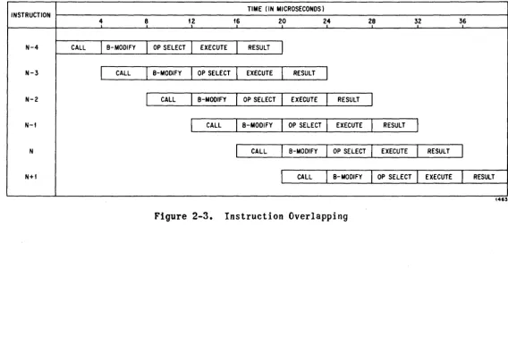
It was stated in the introduction to this section that instructions are not processed serially by the control unit but overlap in time with preceding and succeeding instructions. The preceding paragraph explained how a single instruction was decoded and executed. The many stages in the process can be reduced to five basic operations, named in order, call in-struction. B modification, operand select, execute, and result. Each of these operations can be considered to require 4 microseconds to carry out. The 4-microsecond time unit, known as a memory cycle, is the time actually
required to read a word from or into a storage location.
Figure 2-3 shows a series of instructions passing through the above five stages. The instructions are staggered by a period of 4 micro-seconds. When instruction N is being called from storage. the previous instruction N - 1 is having its M address modified, the operands for N - 2 are being brought from memory, the AU is executing N - 3 and the results of N - 4 are being stored. In the next memory cycle, N
+
I is called from memory, N is B-modified, and so on.l\,)
I '""'"
o INSTRUCTION
N-4
N-3
N-2
N-t
N
N+f
4
CALL
I
B-MODIFYI
CALLTIME (IN MICROSECONDS)
8 t.2 t6 20 24 2~8 32 36
I
OP SELECTI
EXECUTEI
RESULTJ
I
B-MODIFYI
OP SELECTI
EXECUTEI
RESULTI
I
CALLI
B-MODIFYI
OP SELECTI
EXECUTEI
RESULTI
I
CALLI
B-MODIFYI
OP SELECTI
EXECUTEI
RESULTI
I
CALLI
B-MODIFYI
OP SELECTI
EXECUTEI
RESULTI
l
CALLI
B-MODIFYI
OP SELECTI
EXECUTEI
RESULT1463
As an example of the use of the chart in figure 2-3, consider a se-quence of instructions which contains an unconditional-transfer-of-control instruction. (See figure 2-4.) This instruction (N) merely transfers con-trol to the instruction in the storage location specified by the modified M address of the transfer-of-control instruction. The instruction follow-ing the control transfer (N
+
1) will therefore never be needed. However,due to the overlap of instructions, the instruction in location
N
+1
will in fact be called for before the computer has fully decoded theunconditional-transfer instruction (operand-select cycle). Therefore, when the control unit has decoded the control-transfer instruction, a signal is sent which prevents instruction N
+
1 from entering the first instruction register. The instruction specified by the M digits of the unconditional-transfer-of-control instruction will be called for in the next memory cycle. Thus, a memory cycle has been lost during the transfer of control. Anunconditional-transfer-of-control instruction therefore has an effective execution time of 8 microseconds.
INSTRUCTION ADDRESS
N CALL
( UNCONDITIONAL TRANSFER OF CONTROL TO II)
N+I
M
M+I
TIME (IN MICROSECONDS)
1
,
I~ t~ 2.0 2.4I
B-MODIFYI
OP SELECTI
EXECUTEI
RESULTI
SToJ~+t
I
CALL11---
___ ....L ___ ....L ___ ....L ___--r - - - --r - - - --r - - --,
..J USE M FORNEXT. CAlL
I
CALLI
B-MODIFYI
OP SELECTI
EXECUTEI
I
CALLI
B-MODIFYI
OP SELECTI
Figure
2-4.
Sequencing of an Unconditiona1-Transfer-of-Control Instruction2.8
RESULT
I
EXECUTE
I
RESULT4464
2-14. CONTROL OF ERRORS, CONTINGENCIES, AND THE TRACING MODE
These three topics are dealt with at length in section 7. However, this section gives a useful brief description of the function of the con-trol unit in these three areas.
An error is usually caused by a computer failure of some kind. How-ever, incorrect programming also can cause errors to occuri for example, if an instruction contains the address of a non-existent storage location in the M-digit positions an error will be signified when the instruction is executed. There are several error flip-flops in the computer, each relat-ing to a specific error. When the control unit detects an error it sets the related flip-flop or flip-flops. This automatically sets the master error flip-flop during the instruction result time. When the master error
flip-flop has been set, the control unit stores an unconditional-transfer-of-control instruction in storage location 02600 which serves as a return jump to the program. (The M digits of this instruction usually contain the address of the next instruction after the one in which the error occurr~d,
but this is not always so.) Control is then transferred to the instruction in address 02601. Obviously, some routine for diagnosing errors must be in the computer with its first address at 02601. A general discussion of er-ror routines is given in section 7. In general, however, when an erer-ror occurs the computer does not complete the instruction causing the error be-fore entering the error routine, although in a few cases the instruction is actually completed. (See note, page 7-3.)
A contingency is caused by some programming error; overflow and sign anomalies are examples. The control unit handles contingencies in the same way as it does errors, that is, one or more contingency flip-flops are set, causing the master contingency flip-flop to be set. The address of the next instruction after the one in which a contingency occurred is stored as the M address of an unconditional-transfer-of-control instruction in 02700 and control is transferred to the instruction in address 02701. A contingency routine must be stored in the computer with its first instruc-tion in storage locainstruc-tion 02701. A general discussion of contingency rou-tines is given in section 7.
When contingencies occur the address stored in 02700 is always that of the next instruction. An instruction in which a contingency occurs is always completed (and in a few cases the next instruction also is com-pleted) before the computer enters the contingency routine.
The first character of an instruction, known as the tracing digit, is usually a period. Its presence causes normal execution of the instruction. The first character may also be any of the digits 1 through 9.or the ignore
symbol (i).
There are nine tracing mode flip-flops in the Computing Unit corre-sponding to the digits 1 through 9. They may be set as the result of pro-grammed instructions. Whenever the control unit decodes an instruction with one of the digits 1 through 9 in the tracing position, the
correspond-ing flip-flop is tested. If it is in the reset state, the computer con-tinues in normal operation exactly as if a period had been present. If, however, the flip-flop is in the set state, the computer enters the tracing mode before the instruction is executed.
When the computer enters the tracing mode control is in fact trans-ferred to the error routine exactly as if an error had occurred. The error routine must be so written as to detect the tracing mode and transfer to a special tracing routine. This facility is designed to assist a programmer in debugging programs. The tracing routine, for example, may be programmed to print out the contents of certain registers before returning to the pro-gram. A general discussion of tracing routines is found in section
7.
Itis important to notice that instructions with tracing digits behave like any other instructions as long as the corresponding flip-flops are reset.
SECTION 3
INSTRUCTION DETAILS
The purpose of this section is to introduce the instruction repertory of the Larc Computing Unit. Instructions are presented by class and are described according to their normal use. The execution time in microsec-onds is specified for each instruction. The times given allow for overlap and each time is, in fact, the period that elapses from the end of the pre-vious instruction to the end of the current instruction. (See appendix A for a condensed numerical list of instructions.)
3-1. INSTRUCTION FORMAT
The format of an instruction word for the Larc Computing Unit has al-ready been described in section
2.
Also in that section the mode of execu-tion of an instrucexecu-tion was outlined. In this secexecu-tion, descripexecu-tions of the operation of individual instructions are designed specifically for the programmer's use. They are not intended to be precise descriptions of com-puter logic. In particular, as the contents of control counter 1 (Cl) depend not only on the instruction being executed, but also on the two following (see figure 2-3), this control counter will not be mentioned in instruction descriptions. In order to avoid using CI, a hypothetical con-trol counter C will be used. The contents of the hypothetical counter C, otherwise written as (C), will be the address of the instruction being ex-ecuted; the symbolic notation, (C)+
1 ~ C, means continue with the nextinstruction in sequence; and M ~ C means transfer control to the in-struction in storage location M. The programmer must remember that in fact there is no control counter such as C, and that C has been introduced
mere-ly as a device to simplify descriptions.
It will have been noted that there are three addresses in the Comput-ing Unit instruction word. Two of these (A and B) are fast-register ad-dresses and the third (M) may be either a fast-register address or a core-storage address. If any of these addresses in an instruction word exceeds the maximum available, errors will usually occur when the instruc-tion is decoded. In a few instrucinstruc-tions some of the addresses are not used and may exceed the maximum without causing errors. However, note that in all instructions modification will invariably take place and hence the M digits of the instruction must be numeric even if they are not needed. For the same reason the B address must always specify a fast register and the
The original description of a Computing Unit instruction word as given
in section 2 requires some amplification. The T digit is known as the tracing digit and may be one of the characters 1 through 9, period (.), or ignore symbol (i). If the tracing digit is one of the digits 1 through 9 and the corresponding tracing flip-flop is set, the execution of an instruc-tion is delayed while the computer enters the tracing mode. (This mode is fully explained in section 7.) If the tracing digit is a period (.), the instruction is executed normally. In the examples contained in this sec-tion the tracing digit will always be a period. If the tracing digit is ignore (i), the computer operates in the indirect addressing mode. (This mode is more fully explained in section 6.)
The five M digits of an instruction word usually contain the address of a storage location. The addresses range from 00000 to Lim M; Lim M may vary from system to system but never exceeds 97499. The M digits may, how-ever, be used to address a fast register. In this case the address would be of the form 999AA, where AA is a normal fast-register address.
The A and the B digits of an instruction usually specify fast-register addresses. These range from 01 to Lim A; Lim A never exceeds 99. In the Larc system (serials 1 and 2), Lim A is, in fact, less than 99. The refer-ences to Lim A in the manual therefore assume this fact. Note, however, that in a Larc system with a full complement of fast registers, certain of the error conditions listed in this manual will not apply.
For example, in a double-precision store instruction (paragraph 3-6), the use of 78 as the A address will cause errors if Lim A is equal to 78, but 99 as the A address will not cause errors if Lim A is equal to 99. The reason for this is that when the A address (99) is incremented by 1 to give the address for the second half of the store, the resulting two-digit address will be 00.
The contents of a fast register may either be interpreted as a normal operand or as a counter and modifier. In the latter case the fast register is referred to as an index register. It should be noted that any fast re-gister may be used as an index rere-gister.
3-2. INDEX REGISTER FORMAT
The contents of a fast register used as an index register have the following format:
NNN DDDD AAA66
The three N digits are known as a cycle counter. The repertory of the com-puter contains index-register instructions which reduce the counter of an index register and test it for zero. The five 6 digits are known, collec-tively, as the address modifier. These are the digits that are used in an instruction to modify the M address. The D digits are used by index regis-ter instructions to increment or decrement the address modifier.
\
decimal zeros (.00000000000). This operand is permanently stored in the computer and cannot be changed by the programmer.
3-3.
OPERANDSIn arithmetic operations the Larc Computing Unit interprets the oper-ands as numbers. Numbers may be stored in the Larc computer in four dis-tinct ways as follows:
(1) Single-precision, fixed-point fractions.
(2) Double-precision, fixed-point fractions.
(3) Single-precision, floating-point numbers.
(4) Double-precision, floating-point numters.
A single-precision, fixed-point number has the following format:
SI\XXXXXXXXXXX
where S is the sign digit and X represents any decimal digit. The decimal point is automatically taken to be between the sign and the most signifi-cant decimal digit. A single-precision, fixed-point operand is thus a signed II-digit fraction.
A double-precision, fixed-point number consists of two Larc computer words and has the following format:
SI\XXXXXXXXXXX 5 XXXXXXXXXXX
This number represents a signed, 22-digit fraction. The decimal point is automatically taken to be between the sign and the most significant deci-mal digit of the left-hand, or most significant word. In double-precision arithmetic instructions the most significant word is addressed; the least significant word is always taken from the next higher storage location or fast register. The signs in both halves of a double-precision operand should agree.
A single-precision, floating-point number in the Larc Computing Unit has the following format:
SEE XXXXXXXXX
1\
where 5 and X have the same interpretation as before and the E digits re-present an excess-50 power of ten, or exponent. The decimal point is taken to be between the E digits and the most significant decimal digit. A single-precision, floating-point number thus represents a signed, nine-digit fraction raised to some power of ten (EE - 50). The operand
should always be normalized, that is, the most significant X digit should not equal zero. Floating-point results produced ~y the computer are nor-malized automatically. The fractional part of a floating-point number will
The ranges of a single-precision, floating-point number (N) are as
follows:
- .999999999 x 1049
~
N~
- .1 x la-50and
.1 x 10-50
~
N~
.999999999 x 1049The format of a double-precision, floating-point number is:
SEEAXXXXXXXXX 5 XXXXXXXXXXX
This number represents a floating-point number with a mantissa of 20 deci-mal digits. The decideci-mal point is taken to be in the most significant word
immediately following the exponent. The signs of both words should agree and the mantissa should be normalized.
The ranges of a double-precision, floating-point number (N) are as follows:
- .99999999999999999999 x 1049
~
N~
- • 1 x la- 50and
.1 x la-50
~
N~
.99999999999999999999 x 1049The rules for addressing a double-precision, floating-point number are the same as those for a double-precision, fixed-point number.
The character in the sign position of a number should be one of the following:
(1) Zero (0), indicating that the number is positive.
(2) Minus (-), indicating that the number is negative.
(3) Period (.), indicating a special use of the number. (This is ex-plained further in paragraphs 3-7 and 3-13.)
Variations in the use of the sign digit depend on the type of operation. They will be discussed under the appropriate headings in the instruction
repertory.
The format of Larc alphanumeric words is discussed in section 4 in
connection with input-output equipment operations.
3·4. FLOATING·POINT ARITHMETIC
Overflow, as understood in the fixed-point sense, does not occur in floating-point operations. Whenever the mantissa would overflow it is shifted right and the exponent is increased by 1. However, if the exponent becomes greater than its maximum permissible value (99), an exponent over-flow contingency will occur. In a similar way, if the result is found to be non-normalized, the computer shifts the mantissa to the left and de-creases the exponent accordingly. If the exponent is Qecreased so that it becomes less than zero, an exponent underflow contingency will occur.
Normally, the result exponent after overflow or underflow has occurred will be meaningless. If the programmer needs to have this information, he may use the following general rule: calculate the result by using the true floating-point representations of the operands (that is, subtract the ex-cess 50 from the exponents), add 50 to the result exponent,and take the ten's complement if the excess-50 result exponent is negative. (For ex-ample, the computer representation of an excess-50 exponent of -34 would be 66.) This will give the result exponent.
The following table gives the range of result exponents for all floating-point operations in which an exponent overflow or underflow con-tingency occurs:
Operation Exponent Range Exponent Range (overflow) (underflow)
Add or subtract (single precision) 00 99-91
Add or subtract (double precision) 00 99-80
Multiply (single or double
pre-cision) 00-48 99-49
Divide (single or double precision) 00-50 99-51
If the computer uses non-normalized operands in a floating-point com-putation it is possible for contingencies to occur. Hence, the floating-point representation of zero requires special treatment, as zero cannot be normalized. In the Larc Computing Unit, positive or negative zero will cause contingencies but the computer is designed to handle absolute zero (period and 11 zeros) without causing contingencies. In all cases where a zero is required, the programmer should use absolute zero or a small posi-tive or negaposi-tive number to avoid contingencies.
It is possible for a floating-point computation to result in zero. For example, if the two operands below are added, the result will be as shown:
Operands
Result
o
50 347263157 -50 347263157o
41 000000000The initial result in the arithmetic.unit would, of course, be:
o
50 000000000In attempting to normalize, the arithmetic unit would shift the mantissa nine places to the left and reduce the exponent by the number of shifts. In failing to normalize, the arithmetic unit would set the zero floating-point adder result contingency flip-flop and transfer control to the con-tingency routine. This routine must be designed to replace the zero result by some approximation of the true result. If we assume that, on the aver-age, there is an error of 5 in the tenth place of the mantissa, the approx-imate result before normalizing would be:
o
50 000000000 5Therefore an approximate result of:
o
41 500000000would be the best approximation to replace the zero result. The additional time required by the contingency routine each time a zero result occurs would be a very small percentage of the complete program running time. In special cases, the programmer may wish to use absolute zero to replace a zero produced by addition or subtraction, but in general, the above proce-dure tends to reduce the accumulation of error terms.
3·5. PROGRAM CONVENTIONS
The following programming conventions are used in the remainder of this manual:
M The five M digits of an instruction. These digits usually spec-ify a core-storage address or a fast-register address.
A The two A digits of an instruction. These digits usually spec-ify a fast-register address.
B The two B digits of an instruction. These digits always specify the address of a fast register which is to be used as an index register.
AA The two A digits of the word in fast register A.
•
•
The two A digits and the two B digits of the word in fast regis-ter A.
The five M digits of the word in fast register A.
The tracing digit and the two instruction-designator digits (TIl) of the word in fast register A.
The same notation is used to denote a portion of the word in storage location M; that is, MA, MS' MAB , MM' and MI •
The address of a double precision word stored in two storage lo-cations or two fast registers.
At = A and A
+
IM'
=
M and M + I () The contents of(M) means the contents of storage location M.
( )i The initial contents of
)f The final contents of
I I
The absolute value or magnitude ofI(M)I
means the magnitude of the contents of storage location M.() Floating-point operation
(M) (±) (A) denotes the float i ng point addi t ion of (M) and (A).
Rdd Rounded result.
3-6. DATA-TRANSFER INSTRUCTIONS
Instructions in this class transfer words of data from fast storage to memory, from. memory to fast storage or from one fast register to another. Data-transfer instructions are of two types: single precision, in which the contents of one location are transferred and double precision, in which the contents of two adjacent locations are transferred. In double-precision transfers the word addressed by the instruction forms one half of the oper-and oper-and the next higher word in the memory or fast storage forms the other half.
STORE S
40
4~sT 40 AA SB MMMMM
Transfer the contents of fast register A to storage location M. The
contents of fast register A are not changed.
The instruction will transfer words comprising any combination of le-gitimate Larc characters.
Storing the contents of fast register 00 is a legitimate operation; it will place in the specified storage location a word consisting of a per-iod in the sign position and 11 decimal zeros. For convenience, this num-ber will in the future be referred to as absolute zero, but the programmer should note that in a few instances the quantity will have no numerical sjgnificance.
Words may be stored in a fast register by writing the M address as
999AA, where AA is a fast-register address. For example, the instruction • 40 03 00 99921 will store the contents of fast register 03 in fast regis-ter 21. The M address 99900 should not be used in any store instruction because it will cause errors. Fast register 00 is a special-purpose regis-ter which cannot be written into.
STORE NEGATIVE SN 41 4~s
T 41 AA BB MMMMM
-(A) ---+ M
Transfer the negative value of the contents of fast register A to storage location M. The contents of fast register A are not changed.
Only the sign of the word is altered during the transfer. The altera-tion of the sign takes place according to the rules expressed in the fol-lowing table:
Sign of Word in A
o
Sign of Word in M
o
If the sign of the operand is a character other than (0), (-), or (.), a sign-anomaly contingency will occur. The store operation will take place and a zero will be deposited in the sign position of M.
The other 11 characters in the word transferred may be any combination of legitimate Larc characters.
STORE MAGNITUDE SM 42 4~s
T 42 AA BB MMMMM
I(A)I ~ M
The instruction will transfer words comprising any combination of le-gitimate Larc characters. Only the sign of the word is altered during the transferi the sign is always changed to a decimal zero, regardless of its original value.
Note that the instruction. 42 00 BB MMMMM will store a word consist-ing of 12 decimal zeros in storage location M.
STORE, DOUBLE PRECISION 55 45 B~s
T 45 AA BB MMMMM
(A) - - + M
(A
+
1) ---. M+
1Transfer the contents of fast register A to storage location
M;
then, transfer the contents of fast register A+
1 to storage location M+
1. The contents of fast register A and A + 1 are not changed. The contentsof the fast register may be any combination of legitimate Larc characters.
As in the single-precision store instructions, words may be stored in fast registers by writing the M address as 999AA, where AA is a
fast-register address. For example, the instruction. 45 13 00 99916 will store the contents of fast register 13 in fast register 16, and the contents of fast register 14 in fast register 17.
The double-precision store instruction virtually operates as two single-precision store instructions in sequence. This gives unusual re-sults when an instruction such as • 45 12 00 99913 is executed. In this case, the contents of fast register 12 are stored in fast register 13, and the contents of fast register 13 are then stored in fast register 14. The net effect of the double-precision store instruction is to transfer the contents of fast register 12 to fast registers 13 and 14. In particular, the instruction. 45 00 00 99901 will store absolute zero in fast registers 01 and 02.
There is a special restriction on the use of a double-precision store instruction in the last word position of a memory unit, that is, in storage locations 02499, 04999, etc. If a double-precision store instruction in one of these locations has as its M address the address of the instruction, the next instruction to be executed will be taken from the first location of the next memory unit before the second half of the store takes place. For example, if in location 02499 there is the instruction. 45 06 00 02499, the next instruction will be taken from 02500 before the contents of fast register 07 have been stored there.
It will be seen that the use of Lim A or Lim M as A or M addresses in
any double-precision store instruction will cause errors. The second half of the store will then be dealing with nonexistent fast registers or stor-age locations.
STORE NEGATIVE, DOUBLE PRECISION SSN 46 8~s
T 46 AA BB MMMMM
-(A) ---- M
-(A
+
1) ~ M+
1Transfer the negative value of the contents of fast register A to storage location M; then, transfer the negative value of the contents of fast register A
+
1 to storage location M + 1. The contents of fast reg-isters A and A + 1 are not changed.The sign of each word transferred is altered independently. The signs are altered according to the rules expressed in the following table:
Sign of Word in A
o
Sign of Word in M
o
If the sign of either word is a character other than (0), (-), or (.), a sign-anomaly contingency will occur.
If the signs of both words are incorrect, both halves of the store operation will take place and a 0 will be deposited in the sign positions of M and M
+
1. If the sign of the second word (A+
1) only is incorrect, storage of the first word will take place normally and storage of the sec-ond word will be carried out with a 0 deposited in the sign position of M+
1. If the sign of the first word (A) only is incorrect and M is the ad-dress of a storage location, storage of the first word will take place and a 0 will be deposited in the sign position of M; storage of the second word will take place normally. If the sign of the first word (A) only isincorrect and Mis the addr'e ss of a fast reg i s ter, the storage oJ t be fi rst word will take plac€ and a 0 will be deposited in the sign position of M; storage of the second word will take place with the following rules for the sign digit established by the rules expressed in the following table:
Sign of Word in A
+
1 0Sign of Word in M + 1
o
o
Bad parity combinationThe bad parity combination will not cause errors until a further attempt to use fast register M + 1 is made.
The other 11 characters in each word are transferred unchanged, and may be any combination of legitimate Larc characters.
The double-precision, store-negative instruction virtually operates as two single-precision store instructions in sequence. This gives unusual results in an instruction such as • 46 12 00 99913. In this case, the
negative val~e of the contents of fast register 12 are stored in fast reg-ister 13, and the negative value of tae contents of fast regreg-ister 13 is then stored in fast register 14. The net effect of the instruction is to transfer the negative value of the contents of fast register 12 to fast register 13, and the original contents of fast register 12 to fast register 14.
The special restriction on the use of a double-precision store in-struction in the last word position of a memory unit applies also to the double-precision, store-negative instruction.
STORE MAGNITUDE, DOUBLE PRECISION SSM 47 8~s
T 47 AA BB MMMMM
1
(A)1--"
M1 (A
+
1) I ~ M+
1Transfer the absolute value of the contents of fast register A to storage location M; then, transfer the absolute value of the contents of fast register A
+
1 to storage location M+
1. The contents of fast reg-isters A and A + 1 are not changed.The instruction will transfer words comprIsIng any combination of le-gitimate Larc characters. Only the signs of the two words are altered
dur-ing the transfer. These are always changed to decimal zeros regardless of their original values.
The instruction. 47 12 00 99913 will-have the net effect of transfer-ring the absolute value of the contents of fast register 12 to fast regis-ters 13 and 14.
The special restriction on the use of a double-precision store in-struction in the last word position of a memory unit applies also to the double-precision, store-magnitude instruction. However, it is unlikely that the programmer would use this instruction to store instruction words as the tracing digit of the stored instruction would be zero, causing er-rors if the instruction were executed.
FETCH F 43 4 ~s
T 43 AA BB MMMMM
(M) --- A
Transfer the contents of storage location M to fast register A. The contents of storage location M are not changed.
The instruction will transfer words comprising any combination of le-gitimate Larc characters.
Words may be fetched from a fast register by writing the M address as 999AA, where AA is a fast-register address. In particular, the
instruc-tion •
43 01 00 99900
will have exactly the same effect as the instruction
Note that in this instruction the fast-register address 00 is
not
a valid A address. Errors will occur if any attempt is made to write into this fast register.FETCH, DOUBLE PRECISION FF 40 8~6
T 48 AA BB MMMMM
(M) - - . A
(M
+
1) - . . A+
1Transfer the contents of storage location M to fast register A; then, transfer the contents of storage location M
+
1 to fast register A+
1. The contents of storage locations M and M+
1 are not changed.The contents of the two words transferred may be any combinations of legitimate Larc characters.
As in the single-precision fetch instruction, words may be fetched from fast registers by writing the M address as 999AA, where AA is a fast-register address. For example, the instruction. 48 16 00 99902 will trans-fer the contents of fast register 02 to fast register 16, and transtrans-fer the contents of fast register 03 to fast register 17.
The double-precision fetch instruction virtually operates as two single-precision fetch instructions in sequence. This gives unusual re-sults when an instruction such as • 48 17 00 99916 is executed. In this case the contents of fast register 16 are transferred to fast register 17, and then the contents of fast register 17 are transferred to fast register 18. The net effect of the instruction is to transfer the contents of fast register 16 to fast registers 17 and 18. In particular, the instruction • 48 01 00 99900 will transfer absolute zero to fast registers 01 and 02.
It will be seen that the use of Lim A or Lim M as A or M addresses in the double-precision fetch instruction will cause errors. The second half of the store will then be dealing with nonexistent fast registers or stor-age locations.
3-7. FIXED-POINT ARITHMETIC INSTRUCTIONS
Instructions in this class perform basic arithmetic operations on words representing fixed-point fractions. Single-precision instructions are considered first, followed by double-precision instructions. The mne-monic of every instruction in this class contains an X. Read the X as
'fixed point'.
Characters in the nonsign positions of operands should be numeric only. If one or more of the nonsign positions of an operand contain a non-numeric character. an error will occur and no result will be stored. The M oper-and may be a fast register.
If either operand in a fixed-point addition or subtraction contains a (.) in the sign-digit position. the absolute value of the result will be the sum of the absolute values of the operands, and the sign of the result will be given by the appropriate sign table.
If a sign-anomaly contingency occurs in any fixed-point arithmetic in-struction, the sign of the result will be (0). In a fixed-point addition or subtraction in which a sign-anomaly contingency occurs, the absolute value of the result will be the sum of the absolute values of the operands.
ADD, FIXED POI~l AX 01 4~s
T 01 AA BB MMMMM (M)
+
(A) ---. AAdd the fixed-point fraction in storage location M to the fixed-point fraction in fast register A. Store the sum, with correct sign. in fast register A. The contents of storage location M are not changed.
The sign position in either word may contain any of the characters (0), (-). (.), or one of the digits 1 through 9. The sign of the result is governed by the rules expressed in the following table.
Sign of Sign of Word in M
Word in
A 0
-
• 1 thru 9 i , ~.0 0 0/- 0 1 thru 9 C
-
0/--
-
1 thru 9 C• 0
-
• 1 thru 9 C1 thru 9 1 thru 9 I thru 9 1 thru 9 C C
it 6.
+
C C C C CNOfE
The letter C shows that a sign-anomaly contingency will occur. When the sign of the result can only be determined by the calculation, it is shown as 0/-.
+
If the absolute value of the sum is greater than I, a fixed-point overflow contingency will occur.
NEGATIVE ADD, FIXED POINT NX 11 4~s