Dynamic pile impedances for fixed-tip piles
George Anoyatis
Senior Lecturer, University of the West of England, Bristol, UK, email: george.anoyatis@uwe.ac.uk
Raffaele Di Laora
Research Fellow, Second University of Naples, Naples, IT, email: raffaele.dilaora@unina2.it
Anne Lemnitzer
(Corresponding Author)
Assistant Professor, University of California Irvine, Irvine, U.S., email: alemnitz@uci.edu
ABSTRACT
The behavior of a laterally loaded pile with fixed-tip boundary condition (i.e., displacement and rotation, are perfectly restrained) is evaluated using a recently proposed, improved Tajimi-type model. The model performance in both, static and dynamic regime is first validated against rigorous finite element solutions and subsequently compared with Winkler model results for a selected range of pile-soil system parameters. In addition, pile impedances for fixed-tip piles are compared with previously proposed impedance expressions for hinged-tip piles. Results indicate that pile tip fixity has moderate impact on the pile stiffness in rotation but show stronger influence for pile stiffness in swaying and cross-swaying. The effect of tip fixity on pile impedances diminishes when piles are longer than approximately ten pile diameters. The proposed expressions for damping were evaluated across a wide range of frequencies, and damping was found to be most pronounced in rotation across the entire spectrum of pile-soil stiffness ratios examined. Winkler based formulations from literature almost exclusively over-predict damping for fixed tip piles.
1. Introduction
The consideration of dynamic soil-structure-interaction (SSI) is crucial to correctly assess the seismic vulnerability of a structure. The traditional assumption of a fixed-base condition at the foundation level is known to misrepresent the effects of SSI on the structural response by altering the period and damping of the system. Contrarily, the implementation of soil-foundation compliance leads to correct understanding of structural stiffness and damping; however, the significant increase of computational time and costs associated with complex SSI analyses poses considerable disadvantages. Therefore, simpler computational tools that provide the engineer with the capability to assess potential SSI effects on the structural response are beneficial.
For structures resting on pile foundations, approximate three-dimensional Tajimi-type formulations can be implemented to evaluate analytically soil-structure interaction resulting from lateral loading via closed form expressions. These formulations can yield results for pile impedances [dynamic pile head stiffness in
swaying, rotation and cross swaying-rotation (Khh, Krr, Khr) and corresponding damping ratios (ζhh, ζrr,
ζhr)] to be readily implemented in subsequent superstructure analyses. Pile impedances depend on the pile
boundary conditions and therefore the consideration of pile tip fixity may be of importance, especially for “short” piles. While elastodynamic models published in the literature provide rigorous solutions for piles embedded in a half-space, these models do not account for the structural fixity condition at the pile tip (e.g. [1], [2]).
Several researchers have proposed simple expressions for pile impedance functions for a variety of pile boundary conditions. Static pile impedances (pile head stiffnesses K) have been presented by Gazetas [3] and Syngros [4] through curve fitting of finite element (FE) results of piles embedded in a homogeneous
half space. Specifically, Gazetas and Syngros proposed relationships for static swaying (Khh), rotation (
Krr), and cross swaying-rotation (Khr) as a function of the pile-soil stiffness ratio. Yet, similarly to
rigorous elastic solutions described earlier, these expressions ( [3], [4]) fall short in their ability to accurately capture the dynamic response and are limited in their applications to “long piles” (i.e., no effect of tip fixity is considered). The performance of the Syngros and Gazetas expressions has been tested in Anoyatis and Lemnitzer [5] where an extensive parametric analysis for static pile impedances was conducted for the case of hinged-tip piles.
Roesset and Angelides proposed frequency-dependent expressions for dynamic pile stiffnesses Khh, Krr,
Khr (yet not for pile damping). In both research efforts, expressions for stiffnesses are a function of the
Winkler modulus. This indicates that their performance strongly depends on the selection of a proper value for the modulus. Using frequency independent (“static”) expressions for the Winkler springs (e.g.
[8]), pile stiffnesses will not be able to account for resonant effects (significant “drop” in Khh, Krr, Khr at
resonance) and will exhibit a monotonic variation with excitation frequency. Note that the expression for pile damping in swaying presented by Dobry et al. [6] accounts for resonant effects through a two-part equation (i.e., manually), by separating the expression into a “before” resonance and “after” resonance term which accounts for the “jump” in damping by including a Winkler dashpot.
Closed-form expression for dynamic pile impedances are available in the literature through a simple Winkler model (e.g. [9]). The accuracy of these expressions, along with the expressions from Dobry et al. [6] and Roesset and Angelides [7] previously discussed, strongly depends on the selections of proper values/expressions for the Winkler moduli [dynamic stiffness k and dashpots c (or damping ratio β)].
Note that a thorough discussion on the effect of existing Winkler moduli [dynamic stiffness k and
dashpots c (or damping ratio β)] on dynamic pile impedances is presented in Anoyatis & Lemnitzer [5], where new expressions for k and β were presented. The majority of moduli available in the literature were either frequency- or resonance- independent and fell short in yielding realistic results for dynamic pile impedances, especially at frequencies close to the first resonance of the soil-pile system.
Alternatively, simple Winkler models can treat the problem of a pile embedded in a soil layer overlying rock and consider pile tip restraints. However, existing expressions for Winkler springs and dashpots are not calibrated for fixed tip conditions. Therefore, a need for closed-form expressions to accurately evaluate pile stiffness and damping for piles socketed in shallow rock, emerges. Previously, effects of tip fixity on pile impedances have been recognized by Novak and Nogami [10], however, pertinent expressions have not been published and are not available for users.
assessed through comparison with the results obtained from the proposed model. Note that the ability of the model to accurately predict damping is of particular importance when performing SSI analyses (Maravas et al. [11], Bilotta et al. [12]). Substantial benefits in terms of reduction of structural accelerations may be achieved when the structural frequency is larger than the fundamental frequency of the soil as shown in ensuing graphs.
The current study assumes an idealized configuration in which the pile tip is perfectly fixed at the elevation of the bedrock. The Authors acknowledge that in situ conditions encountered in engineering design practice may vary, as the level of tip fixity depends on the strength and condition of the rock, which is often approximated. The Authors further acknowledge that the degree of fixity intrinsically influences the ability of the pile to rotate within the embedment socket (e.g., if rock is weathered). With the assumption of a perfectly fixed tip and the solution provided in Anoyatis and Lemnitzer [5], who investigated the condition of the pile with a hinged tip, the pile response at both ends of the pile tip boundary spectrum is fully described.
2. Pile-soil configuration
The pile-soil configuration examined in this study is depicted in Fig. 1 (a): a cylindrical pile of diameter d
and length L is embedded in a homogenous soil layer of thickness H (¿L) and fixed in a medium with infinite stiffness. The pile is modelled as a vertical cylindrical beam in the framework of the
strength-of-materials solution ( [10], [5]) and is described by its Young’s Modulus Ep and mass densityρp. The soil is
characterized by a mass density ρs and Poisson ratio νs. The hysteretic damping βs is implemented in the
analysis through a complex-valued shear modulus Gs
¿
=Gs
(
1+2i βs)
. The pile is subjected to thefollowing loading: (i) a harmonic horizontal load P eiωt applied at the pile head which generates
horizontal harmonic oscillations of the form w
(
z , ω)
eiωt, as well as (ii) a static load P which generatesstatic displacements in the form ofw
(
z)
. In the aforementioned formulations, z represents the spacevariable in vertical direction; t represents time; ω describes the cyclic excitation frequency; and i is the imaginary number. As a result of the applied loading, the soil surrounding the pile undergoes harmonic motion or static displacements which will be expressed through the radial and tangential displacement
components, ur
(
r , θ , z , ω)
and uθ(
r ,θ , z , ω)
, respectively. In an earlier publication, Anoyatis andbase (Fig. 1c). Prior to assessing the static and dynamic pile response of the SSI system depicted in Fig. 1, the improved analytical formulation introduced by Anoyatis and Lemnitzer [5] will be summarized to provide insight and guidance for the ensuing studies.
3. Previous knowledge
Equations (1) and (2) describe the general pile response in terms of pile displacement and rotation, w and φ, respectively, and provide expressions for the internal moment M and shear force Q along the pile for dynamic and static loading conditions. The derivation of Eqs. (1) and (2) is presented in detail in the recent publication by Anoyatis and Lemnitzer [5] where the pile-soil interaction problem in lateral mode was tackled by treating the pile as a beam using traditional strength-of-materials assumptions. A suite of general expressions was obtained by solving the governing differential equations established from the equilibrium of lateral forces acting on a pile segment in the horizontal direction for static and dynamic loading. The constants A, B, C, D are to be determined using the boundary conditions associated with the problem. Anoyatis and Lemnitzer restricted this analysis to the case of a hinged-tip pile and presented (for the sake of brevity) only the expressions associated with the problem at hand; hence, the matrix columns associated with a fixed-tip pile were eliminated. In this manuscript, equations (1) and (2) are presented in their full length. Note that both, in the current study and in Anoyatis and Lemnitzer, the soil is modelled as a continuum using a modified Tajimi model, as presented in detail in Anoyatis et al. [13] where the horizontal reaction of the soil medium to a harmonically oscillating pile was analyzed.
To reiterate, the constants A, B, C and D in Eqs. (1) and (2) are functions of pile and soil parameters as
well as the geometry of the soil-pile system (i.e., L/d, Ep/Es, νs) for the case of static loading, and
additionally function of “dynamic” parameters (i.e., ω d/Vs, pp/ps, βs) for the case of dynamic loading.
3.1. Dynamic conditions
For piles subject to dynamic loading, the response can be obtained through the following general matrix formulation:
(1)
3.2. Static conditions
In static conditions, the solutions for the pile response parameters takes the following form:
In Eqs. (1) and (2), ~M and ~Q stand for the ratio of the pile moment M and shear force Q, respectively,
over the pile flexural stiffness (i.e., M/EpIp and Q/EpIp). The mth soil eigenmode Φ
m
(
z)
, can beobtained as follows: Φm
(
z)
=sinamz. The first derivative Φm'(
z)
to the eigenmodes, Ym(
z)
, can bedetermined as Ym
(
z)
=cosamz, wherea
m=
π
(
2
m
−
1
)/
2
H
and m=1,2,3, … .Expressions for the parameters f1m, f2m, f3m, f4m in the above equations can be found in Appendices A
and B in Anoyatis and Lemnitzer [5] for dynamic and static loading conditions, respectively.
4. Pile Impedances
The stiffness matrix at the pile head is written as
(3)
where Khh, Krr and Khr
(
¿Krh)
represent the stiffness in swaying, rocking and cross swaying-rockingmode. (*) indicates that the stiffness term is complex-valued, which in its general form can be expressed
as K¿
=K
(
1+2i ζ)
(complex valued pile impedances). Hereby, K=ℜ(
K¿)
represents the dynamic pilestiffness and ζ= ℑ
(
K¿)
/2ℜ(
K¿)
the pile damping (both K and ζ being frequency-dependent). Note thatζ is different from the hysteretic (frequency-independent) material damping βs, which is strictly a soil
property.
By applying a strictly horizontal unit displacement at pile head (i.e., w=1 and φ=0 at z=H) the
stiffness terms Khh and Krh can be obtained as follows (Fig. 1)
(4a, b)
Similarly, by imposing a unit rotation at pile head with zero horizontal displacement (i.e., w
(
H)
=0 andφ
(
H)
=1) the stiffness terms Krr and Khr (Fig. 1) can be expressed as:(5a, b)
In Eqs. (4) and (5), Q
(
H)
and M(
H)
are the shear force and moment at the level of pile head(
z=H)
,and D depend on the type of loading (static or dynamic) and the stiffness to be determined (i.e., Khh, Krr,
Khr) and are provided in closed-form expressions in the Appendices A to D.
The fixed tip condition allows neither displacement [w
(
0)
=0] nor rotation [φ(
0)
=0] to develop.Therefore Eq. (1) simplifies to the following formulation for the case of a dynamically loaded fixed-tip pile:
(6)
which directly suggests that
(7a)
and
(7b)
For the case of static loading, the bottom fixity conditions can be expressed through Eqs. (2) as
(8)
which yields
(9a)
and
(9b)
4.1. Dynamic pile impedances
(10)
(11a)
Expressions for constants A, B and D Eqs. (10) and (11a) are presented in Appendix A.
(11b)
(12)
Expressions for constants A, B and D in Eqs. (11b) and (12) are presented in Appendix B.
4.2. Static pile impedances
The stiffness expressions for swaying and cross-swaying under static loading can be summarized as:
(13)
(14a)
Expressions for constants A, B and C Eqs. (13) and (14a) are presented in Appendix C.
(14b)
(15)
Expressions for constants A, B and C Eqs. (14b) and (15) are presented in Appendix D.
Prior to conducting parametric evaluations of the pile response, the fundamental ability of the proposed model to predict dynamic pile impedances is assessed by comparing its results against such obtained from the finite element solutions using the commercial software ANSYS ( [14]). The numerical model was originally developed by Di Laora and Rovithis [15] to investigate the behavior of kinematically-stressed piles, and was later used to provide reference results for stiffness and damping in the work of Anoyatis and Lemnitzer [5], where the companion problem of a hinged-tip pile was investigated. Hereby, the original three-dimensional soil-pile system is appropriately reduced to a two-dimensional system, by taking advantage of the axisymmetric geometry and the anti-symmetric load (see Wilson [16]). Via sensitivity analyses, the optimum model configuration was iterated and led to the selection of four-node axisymmetric 2D elements with vertical dimensions equal to d/4 and horizontal dimensions varying from d/6 at pile-soil interface to 1.5d at the lateral boundaries. Vertical displacements were restrained at the axis of symmetry and at the lateral boundary of the model, which was placed 200d away from pile axis to permit attenuation of travelling waves. Perfect bonding between pile and soil is considered. The base nodes were restrained against both radial and vertical motion to model a rigid bedrock.
Comparisons of the proposed dynamic pile stiffnesses and damping ratios with results obtained from FE analyses ( [14]) are shown in Figs. 2 – 7. Various pile-soil systems with slenderness ratios L/d ' s equal to
5, 10, 20 and different pile-soil stiffness ratios Ep/Es equal to 100, 1000, 5000 were selected to demonstrate the model performance across a wide range of frequencies (from 0 to approximately five
times the fundamental frequency of the soil). The analysis considers soil hysteretic damping βs=0.05, a
poisson ratio of νs=0.4 and a pile-soil density ratio ρp/ρs of 1.25. Figures 2 – 7 show that the proposed
model is in very good agreement with the FE results and the dynamic effects in proximity of resonance are captured accurately. A clear “dip” in stiffness, and a clear “jump” in damping curves at first resonance is visible. Additionally, resonance effects associated with higher eigenmodes are captured well for piles with larger slenderness ratios. An error analysis was conducted to assess the discrepancy between the model and FE results. Figure 8 presents the error as discrepancy between the model and FE datapoints as percentage and indicates the majority of all error data points to be significantly less than 10 % among all parameters evaluated in Fig. 8. The “average error” shown as solid line across the entire frequency range was found to be around 5 % or less. This capability makes it suitable for implementation in structural analyses by taking into account the benefits stemming from energy radiation in the soil.
Closed-form expressions shown in Eqs. (10) – (15) are used to obtain results for pile head stiffness and damping using a suite of pile slenderness ratios across a wide range of frequencies. The model performance in the static and dynamic regime is discussed separately below:
Static pile head stiffness
The variation of static pile stiffness in swaying, rotation and cross-swaying is shown for pile-soil stiffness
ratios of Ep/Es=100,300,1000,5000, and across a range of pile slenderness ratios for which tip
boundary condition may affect the pile head response, i.e., 5≤ L/d ≤20.
Figure 9 demonstrates that the lower is the ‘mechanical slenderness’ (Anoyatis et al. [13]) of the pile, the more pronounced is the effect of the tip restraint. In example, short piles with slenderness ratios of L/d 5 show the strongest sensitivity to the fixed tip boundary condition with the effect being most
pronounced when stiff piles are placed in very soft soils (e.g., Ep/Es>1000). For L/dratios higher than
10, the stiffnesses are independent of the geometrical slenderness ratio L/d, and the pile can be treated as long, i.e., tip fixity conditions can be ignored.
Figure 10 depicts the ratio of static pile stiffness for fixed-tip piles to hinged-tip piles across a variety of
pile slenderness ratios. The effect of pile tip fixity is most pronounced in the swaying stiffness Khh with
stiffness ratios exceeding 2.0 for piles in very soft soils (e.g., Ep/Es=5000), followed by the
cross-swaying stiffness Khr. The rotational stiffness Krris least influenced by the pile tip boundary conditions,
as the pile head rotation is primarily influenced by the soil pile system characteristics within zero to four pile diameters below the soil surface.
Dynamic pile head stiffness
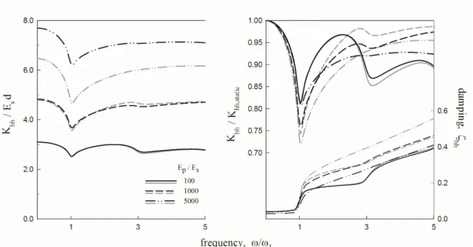
Figures 11 through 13 provide a comparison of proposed results for the fixed tip against the hinged tip
pile for all three stiffness and damping components. For pile-soil ratios Ep/Es up to 1000, pile stiffness
Khh, Krr and Khr show almost identical behavior across the entire frequency range examined. For very
soft soil conditions, a noticeable difference in pile stiffness can be observed, the largest difference being
results for stiffer soils, e.g., Ep/Es=100are aligned with each other; pile stiffness in softer soils are
shown to diverge with the largest differences observable in the normalized swaying stiffness Khh.
The damping in all three modes can be considered constant prior to resonance. While damping for
swaying and cross-swaying indicates almost no influence of Ep/Es below ω/ω1 (i.e., all lines collapse
into one line), only damping in rotation, ζrr, is influenced by the stiffness of the pile-soil system as
demonstrated by the small spacing among all damping curves prior to approaching resonance frequency. At resonance, all damping modes experience a sudden increase, followed by an approximate linearly
trending increase with increasing frequencies. In stiff soil conditions (Ep/Es=100,), damping ζhh and
ζhr align well with each other throughout the entire frequency range. Differences between fixed and
hinged tip piles are obvious near resonance for ζrr in stiff soils. Beyond ω/ω1 = 1, differences between
fixed tip and hinged tip pile damping become more pronounced. While damping ratios ζhh and ζhr for
medium stiff soils follow each other closely, larger differences are noticeable for ζrr. Results obtained for
soft soil conditions show a strong divergence across all damping modes.
7. Comparison with Winkler model
The proposed model is compared against stiffness and damping formulations obtained from literature. Springs and dashpots proposed by Baranov-Novak ( [17], [18]), Dobry et al. [6], Gazetas and Dobry [19], Makris and Gazetas [8], and Mylonakis [20] as summarized by Anoyatis and Lemnitzer [5] are implemented in a Winkler model and compared with results from Eqs. 10 – 15 in Figs. 14 and 15.
Note that the stiffness matrix from the Winkler model ( [9]) can be expressed as:
K¿ =
[
4EpIpλ
3 sin
(
2λ H)
+sinh(
2λ H)
2+cos
(
2λ H)
+cosh(
2λ H)
2EpIpλ2 −cos
(
2λ H)
+cosh(
2λ H)
2+cos(
2λ H)
+cosh(
2λ H)
2EpIpλ2 −cos
(
2λ H)
+cosh(
2λ H)
2+cos
(
2λ H)
+cosh(
2λ H)
2EpIpλ−sin
(
2λ H)
+sinh(
2λ H)
2+cos
(
2λ H)
+cosh(
2λ H)
]
(16)
where
λ=
[
k(
1+2i β)
−ω 2~mp 4EpIp
]
and ~mp=ρpAp, where Ap is the pile cross sectional area.
Figure 14 compares the dynamic stiffness of the proposed model with results from Winkler based formulations. The expressions suggested by Dobry et al. [6] fail to represent the pile stiffness across the entire frequency range. As expected, the plane strain spring and dashpot by Baranov-Novak cannot capture the dynamic effects associated with resonance but can be used to estimate pile stiffness at
frequency ratios of ω/ω1 ¿ 3. While Makris and Gazetas [8] does not perform well for Khh, better
performance is achieved for Krr beyond resonance and Khr at high frequencies. Solutions obtained using
Gazetas and Dobry [19], provide a good estimation for Krr beyond resonance and for Khh and Khr
beyond ω/ω1 ¿ 3. Even though Mylonakis [20] underestimates the resonance stiffness in swaying and
rotation, the expression renders the Winkler model capable of predicting the dynamic stiffness in swaying-rotation over the whole frequency range.
Figure 15 compares pile damping ratios for all three modes. With the exception of Baranov-Novak, the Winkler model using the simple expressions is capable of capturing damping below resonance. At resonance, all Winkler curves exhibit a sudden increase which accounts for the emergence of radiation
damping. For frequencies higher than ω/ω1=1, all Winkler expressions overestimate damping ratios ζhh
and ζrr , in some cases over 20 %. Damping in cross-swaying –rotation, can be reasonably estimated by
Gazetas and Dobry, and Makris and Gazetas. For frequency ratios higher than ω/ω1 = 0.4,
Baranov-Novak can also be used. However, simplified springs and dashpots are unable to capture the effects associated with resonance in higher modes.
8. Conclusions
Tip restraint is frequently encountered in pile engineering (rock-socketed pile); therefore, this work aims at providing closed-form expressions to assess the influence of tip fixity on pile impedances (stiffness and damping).
moderate impact on the pile stiffness in rotation but has a stronger influence on stiffness in swaying and cross-swaying. Damping was found to be most pronounced in rotation across the entire spectrum of pile-soil stiffness ratios examined. Results indicate that a “relaxation” of the idealized perfect tip fixity would result in a reduction of pile stiffness and increase in damping.
APPENDIX Α
Taking into account Eqs. (7) and w
(
H , ω)
=1 and φ(
H , ω)
=0 through the following matrix formequation
(A.1)
constants A, B, and D for
K
hh¿and
K
rh¿are determined as:
(A.2a)
(A.2b)
(A.2c)
(A.3a)
and
APPENDIX B
Taking into account Eqs. (7) and w
(
H , ω)
=0 and φ(
H , ω)
=1 through the following matrix formequation
(B.1)
constants A, B, and D for
K
rr¿and
K
hr¿are determined as:
(B.2a)
(Β.2b)
(B.2c)
Appendix C
Taking into account Eqs. (9) and w
(
H)
=1 and φ(
H)
=0 through the following matrix form equation(C.1)
constants A, Band C for determining static stiffnesses Khh and Krh
(C.2a)
(C.2b)
(C.2c)
where
Appendix D
Taking into account Eqs. (9) and w
(
H)
=0 and φ(
H)
=1 through the following matrix form equation(D.1)
constants A, Band C for determining static stiffnesses Krr and Khr
(D.2a)
(D.2b)
(D.2c)
where
References
[1] R. K. N. D. Rajapakse and A. H. Shah, "On the lateral harmonic motion of an elastic bar embedded in an elastic half-space," International Journal of Solids and Structures, vol. 23, no. 2, pp. 287-303, 1987.
[2] R. K. N. D. Rajapakse and A. H. Shah, "Impedance curves for an elastic pile," Soil Dynamics and Earthquake Engineering, vol. 8, no. 3, p. 145–152, 1989.
[3] G. Gazetas, "Foundation vibrations," in Foundation Engineering, Springer US, 1991, p. 553–593.
[4] C. Syngros, "Seismic Response of piles and pile-supported bridge piers evaluated through case histories," Ph.D. Thesis, City University of New York, 2004.
[5] G. Anoyatis and A. Lemnitzer, "Dynamic pile impedances for laterally–loaded piles using improved Tajimi and Winkler formulations," Soil Dynamics & Earthquake Engineering, vol. 92, p. 279–297, 2017.
[6] R. Dobry, E. Vicente, M. O’Rourke and J. M. Roesset, "Horizontal stiffness and damping of single piles," Journal of Geotechnical and Geoenvironmental Engineering ASCE, vol. 108, no. 3, pp. 439-459, 1982.
[7] J. M. Roesset and D. Angelides, "Dynamic stiffness of piles," in International Conference on Numerical Methods in Offshore Piling, Institution of Civil Engineers (ICE), London, 1980.
[8] N. Makris and G. Gazetas, "Dynamic pile-soil-pile interaction. Part II: Lateral and seismic response," Earthquake Engineering and Structural Dynamics, vol. 21, no. 2, pp. 145-162, 1992.
[9] G. Mylonakis, "Contributions to Static and Dynamic Analysis of Piles and Pile-Supported Bridge Piers," Ph. D. thesis, State University of New York at Buffalo, 1995.
[10] M. Novak and T. Nogami, "Soil-pile interaction in horizontal vibration," Earthquake Engineering & Structural Dynamics, vol. 5, no. 3, pp. 263-281, 1977.
[11] A. Maravas, G. Mylonakis and D. Karabalis, "Simplified discrete systems for dynamic analysis of structures on footings and piles," Soil Dynamics and Earthquake Engineering, Vols. 61-62, pp. 29-39, 2014.
[13] G. Anoyatis, G. Mylonakis and A. Lemnitzer, "Soil Resistance to Lateral Harmonic Pile Motion," Soil Dynamics and Earthquake Engineering, vol. 87, p. 164–179, 2016.
[14] ANSYS 10.0, [Computer software], Canonsburg, PA, ANSYS.
[15] R. Di Laora and E. Rovithis, "Kinematic Bending of Fixed-Head Piles in Nonhomogeneous Soil," Journal of Geotechnical and Geoenvironmental Engineering, vol. 141, no. 4, p. 04014126, 2015.
[16] E. L. Wilson, "Structural analysis of axisymmetric solids," Am. Inst. Aeronautics Astronautics J., vol. 3, no. 12, p. 2269–2274, 1965.
[17] V. A. Baranov, "On the calculation of excited vibrations of an embedded foundation (in Russian)," Voprosy Dynamiki Prochnocti, No. 14, Polytech. Inst. Riga, pp. 195-209, 1967.
[18] M. Novak, "Dynamic Stiffness and Damping of Piles," Canadian Geotechnical Journal, vol. 11, no. 4, pp. 574-598, 1974.
[19] G. Gazetas and R. Dobry, "Simple radiation damping model for piles and footings," J. Eng. Mech., vol. 110, no. 6, pp. 937-956, 1984.
[20] G. Mylonakis, "Elastodynamic model for large-diameter end-bearing shafts," Journal of the Japanese Geotechnical Society : soils and foundation, vol. 41, no. 3, pp. 31-44, 2001b.
[21] R. Flores-Berrones and R. V. Whitman, "Seismic Response of End Bearing Piles," Journal of the Geotechnical Engineering Division, vol. 108, no. 4, pp. 554-569, 1982.
[22] A. S. Veletsos and A. H. Younan, "Dynamic Modeling and Response of Rigid Embedded Cylinders," Journal of Engineering Mechanics, vol. 121, no. 9, pp. 1026-1035, 1995.
FIGURES
Fig. 1. Problem considered: (a) pile-soil system, and (b), (c) deformed pile shape and pile impedances based on different fixity conditions at the tip
Fig. 3. Dynamic pile stiffnesses (Khh, Κrr, Khr) for L/d=10 and different 𝐸𝑝𝐸𝑠⁄ ratios. Comparison of
Fig. 4. Dynamic pile stiffnesses (Khh, Κrr, Khr) for L/d=20 and different 𝐸𝑝𝐸𝑠⁄ ratios. Comparison of
the proposed results against results from finite element analyses (βs=0.05, νs=0.4, pp/ps=1.25)
Fig. 5. Pile damping ratios (ζhh, ζrr, ζhr) for L/d=5 and different Ep/Es ratios. Comparison of the
Fig. 6. Pile damping ratios (ζhh, ζrr, ζhr) for L/d=10 and different Ep/Es ratios. Comparison of the
proposed results against results from finite element analyses (βs=0.05, νs=0.4, pp/ps=1.25)
Fig. 7. Pile damping ratios (ζhh, ζrr, ζhr) for L/d=20 and different Ep/Es ratios. Comparison of the
Fig. 9. Variation of static stiffnesses in swaying, rotation and cross swaying-rotation with L/d for
selected values of Ep/Es ratios
Fig. 11. Dynamic stiffness and damping in swaying (Khh, ζhh); Comparison between fixed-tip (black
curves) and hinged-tip [5] (grey curves)
Fig. 13. Dynamic stiffness and damping in cross swaying-rotation (Khr, ζhr); Comparison between
fixed-tip (black curves) and hinged-fixed-tip [5] (grey curves)
Fig. 14. Dynamic pile stiffness for L/d=10 and Ep/Es=1000. Comparison of the proposed results
against results from the Winkler model using springs and dashpots from the literature (βs=0.05, νs=0.4,
Fig. 15. Pile damping ratios for L/d=10 and Ep/Es=1000. Comparison of the proposed results against
results from the Winkler model using springs and dashpots from the literature (βs=0.05, νs=0.4,