R E S E A R C H
Open Access
Multi-user MIMO MMSE non-regenerative
relaying using local channel state information
Hana Stefanovi´c
1*, Veljko Stankovi´c
2, Mihajlo ˇC Stefanovi´c
1, Petar Spalevi´c
3,
Stefan R Pani´c
4and Srdjan Milosavljevi´c
5Abstract
In this article, we investigate a two-hop relaying communication where all nodes are equipped with antenna arrays. We derive the multiple-input multiple-output (MIMO) processing matrices using the mean-squared-error cost function and assuming that each node uses only locally available channel state information estimates. Spatial processing at the base station and at the user terminals is same as in the case of a direct communication. The emphasis is on the design of the MIMO precoding matrix at the relay as it has to process the noise and the interference on the first and on the second hop at the same time. The resulting system performance is close to the performance of the system that jointly optimizes matrices at the source and at the relay. The proposed solution requires significantly less computational power and feedback overhead than the solutions proposed in the literature.
Keywords: Multi-user MIMO, MIMO systems, Relaying, MMSE processing
Introduction
An important part of future wireless communication sys-tems is multi-user (MU) multiple-input multiple-output (MIMO) processing. It has been shown that the linear increase of the MU MIMO systems’ data rate in the num-ber of transmit antennas can be achieved by serving users simultaneously using the space-division multiple access (SDMA) [1]. In multi-hop-based systems additional, inter-mediate radio access points, or relay nodes (RNs), are used to reduce distances between individual nodes and simul-taneously improve the channel conditions. The relays tra-ditionally have been used to mitigate the effect of path loss for obtaining robust communication. The three-terminal relay channel where a single intermediate node supports a single communication pair was introduced in seminal paper [2]. Different relaying protocols which still serve as a basis for many relaying strategies were proposed later in [3]. The idea of relaying was first applied to wire-less fading channels in [4]. Wirewire-less relays are essential to provide reliable transmission, high throughput, and broad coverage for next generation wireless networks. The
*Correspondence: [email protected]
1Department of Telecommunications, Faculty of Electronic Engineering, University of Nis, Aleksandra Medvedeva 14, 18000 Niˇs, Serbia Full list of author information is available at the end of the article
application of MIMO processing in a wireless relay net-work is designed to provide extended radio coverage and improved spectral efficiency [5].
Relays can be regenerative or non-regenerative. Regen-erative relays employ decode-and-forward (DF) scheme and regenerate the original information from the source. Non-regenerative relays employ amplify-and-forward (AF) scheme, which only performs linear processing of the received signal and then retransmits the signal to the destination. As a result of the above difference, a non-regenerative relays in general cause smaller delays than regenerative relays. Compress-and-forward denotes the case where the relays forward a compressed estimation of their received signal.
Single user, point-to-point communication via relays was extensively investigated in the literature. The MIMO signal processing at the RN that maximizes mutual infor-mation was investigated in [6-8]. The optimization of the minimum mean-squared-error (MMSE) cost function was used to derive the MIMO processing matrix in [9]. A generalized approach to MIMO relaying was presented in [10]. The authors in [6,7,10] either optimize only a MIMO processing matrix at the RN or investigate a joint opti-mization of MIMO processing matrices at the RN and at the source using the global channel state information (CSI).
MU MIMO communication system, where a single source, a base station (BS), communicates with a group of user terminals (UTs) over a single RN was investigated in [11-14]. The optimum design of non-regenerative relays for MU MIMO relay systems in [11] is based on sum rate optimization. Assuming zero-forcing (ZF) dirty paper coding (DPC) at the BS and linear operations at the RN, it proposes upper and lower bounds on the achievable sum rate, neglecting the direct links from the BS to the UTs. The authors in [12] investigate different power allocation algorithms assuming MIMO processing only at the RN. At the BS, there is no processing or simple eigen decomposi-tion is used. At the RN, the authors use QR decomposidecomposi-tion in combination with DPC. In [13], the authors extend the MIMO two-way relaying scheme with XOR precoding to a MU cellular relaying scenario, where a BS communi-cates withKUTs via a single DF relay. Different UTs are spatially multiplexed using ZF beam forming or ZF DPC. A novel iterative semidefinite programming-based algo-rithm is used for sum rate maximization. The problem of joint linear optimization of MIMO processing matri-ces at the RN and at the BS for both downlink (DL) and uplink (UL) in MU non-regenerative MIMO relay systems based on MMSE criterion was investigated in [14]. The resulting MIMO processing matrices are calculated iter-atively, the nodes require the knowledge of global CSI, and the solution for one matrix is a function of the other MIMO processing matrix. As a consequence, we either need to have some central node that would use global CSI to find the optimum MIMO processing matrices or the BS and the RN have to exchange the CSI and the respective MIMO processing matrices. The exchange of the infor-mation between the BS and the RN means that the part of the system throughput has to be used for this pur-pose. Because the algorithm is iterative, the computational complexity and the part of the system throughput that is used for the information exchange will be higher. This significantly reduces the practicality of this algorithm. Additionally, the antenna configuration in [14] considers only single antenna UTs and requires that the number of the antenna at the BS, RN and the number of UTs to be equal. In this article, we consider a more general scenario where the number of the antennas at the BS, RN and UTs is not limited.
In our article, we derive MIMO processing matrices at the BS, RN, and the UTs using MMSE criterion, as opposed to the ZF criterion used in [11-13]. Unlike [14], we assume that these matrices are designed using only local CSI available at the nodes, and the feedback over-head is used only to provide the information about the additive noise variances at the receivers to the trans-mitters. The MMSE criterion is motivated by robustness to channel estimation errors and a lower implementa-tion complexity. Moreover, MIMO processing matrices
designed using the MMSE criterion do not have the same limitations as the MIMO processing matrices that are designed using the ZF criterion, i.e., that the total number of the antennas at the UTs is less than or equal to the num-ber of the antennas at the BS/RN. The use of only local CSI means that the MIMO processing matrix at the BS is designed using only MIMO channel matrix from BS to RN and the MIMO processing matrix at the RN is designed using MIMO channel matrices from BS to RN and from RN to the UTs. Also, our goal is to design MIMO process-ing matrices at the BS and at the RN independently from each other. In [11,14], the authors assume that the BS and RN each have multiple antennas, but that the UTs have only a single receive antenna. We do not have any restric-tions regarding the total number of the antennas at the UTs.
The article is organized as follows. In section “System model”, we describe the relaying system. In section “Design of MIMO processing matrices”, we derive the MIMO processing matrices and in the section “Numerical results”, we present the results of simulations. A short summary follows in the section “Conclusions”.
System model
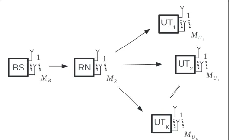
We consider a MU MIMO DL system, where a BS com-municates withKUTs over a single RN. The direct links from BS to the UTs are neglected assuming large path loss. There areMBantennas at the BS,MRantennas at the RN,
andMUk receive antennas at thekth UT,k= 1, 2,. . .,K.
The total number of antennas at the UTs is
MU=
K
k=1
MUk.
We use the notationMU1,. . .,MUK
×MR ×MB to
describe the antenna configuration of the system. A block diagram of such a system is depicted in Figure 1.
The channel matrix from RN to thekth UT is denoted as
H2,k ∈CMUk×MR, and the combined channel matrix from
RN to the UTs is given by
H2=
HT2,1 HT2,2 . . . HT2,KT ∈CMU×MR. (1)
Channel matrix from BS to the RN is denoted asH1∈
CMR×MB. The transmit data vectorsxk ∈ Crk×1, and the
receive data vectorsyk ∈ Crk×1,k = 1,. . .,K, for theK
UTs are stacked in vectors
x=
xT1,. . .,xTK
T
∈Cr×1,
y=
yT1,. . .,yTK
T
∈Cr×1,
whererkdenotes the number of spatially multiplexed data
streams to thekth user.
The input-output signal model is given by the following equation:
y=D H2FRDR
H1Fx+
n1
β1
+n2
β2
, (2)
wheren2=
nT2,1. . .nT2,K
T
∈CMU×1is the stacked
vec-tor of the zero mean additive white Gaussian noise at the input of the UT antenna arrays, andn1 ∈ CMR×1is the
zero mean additive white Gaussian noise vector at the RN antenna array. MIMO precoding matrix at the BS is denoted asF ∈ CMB×r and MIMO receive matrix at the
RN is denoted as DR ∈ Cr×MR. The combined MIMO
precoding matrix at the RN and the combined MIMO receive matrix at the UTs are denoted asFR∈CMR×rand
D∈Cr×MU, respectively
FR=
FR1 . . . FRK
D=
⎡ ⎢ ⎣
D1 · · · 0
.. . . .. ... 0 · · · DK
⎤ ⎥ ⎦,
(3)
whereFRk ∈ CMR×rk is the RN MIMO precoding matrix
corresponding to thek-th UT andDk ∈ Crk×MUk is the
kth UT MIMO receive matrix.
The parameters β1 andβ2 are chosen such to set the total transmit power at the BS and at the RN to PTB
andPTR, respectively. The total number of spatially
mul-tiplexed data streams is denoted as r = Kk=1rk ≤
min(rank(H1), rank(H2)) ≤ min(MB,MR,MU). The
ele-ments of vectorsx,n1, andn2are assumed to be
statisti-cally independent.
Channel estimation
We assume the system operates in time division duplex (TDD) so that we can exploit the estimated UL channel for DL transmission due to the reciprocity principle. In gen-eral, on the DL the UTs need only to estimate the effective MIMO matrix that includes the MIMO processing at the BS to perform the MIMO receive processing. However, on the UL, the BS requires both the effective channel matrix and the over-the-air MIMO channel estimates to perform resource allocation and MU MIMO processing. There-fore, on the DL, we would need only one type of pilot symbols for CSI estimation, while on the UL we need two types of pilots that are used for estimation of over-the-air UT’s MIMO channel matrices and the effective channel matrices. Different types of pilot symbols used in MIMO channel estimation are described in [15]. In our case, the BS has the estimate ofH1, RN has the estimates ofH1F
andH2and the UT has the estimate ofH2,kFRk.
Design of MIMO processing matrices
The design of MIMO precoding matrix at the BS and MIMO receive matrices at the RN and the UTs will be straightforward as we use only local CSI.
At the RN, we have the estimate ofH1F, and the
opti-mum MIMO receive matrixDRis obtained from
DR=min
¯
DR
E
D¯R
H1Fx+
n1
β1
−x
2
(4)
as
DR=RxFHHH1
H1FRxFHHH1 +
1
β12Rn1
−1
, (5)
where Rx = E{xxH} denotes the transmit vector
corre-lation matrix,Rn1 = E{n1nH1}denotes the additive noise
correlation matrix, and(·)H denotes conjugate transpose. Let us define the singular value decomposition (SVD) of the channel matrixH1as
H1=U11VH1. (6)
From [16,17], we can assume that the matrixFis in the form:
F =V(1r), (7)
whereV(1r)contains the firstrcolumns of the matrixV1
and∈Cr×r. Then, from Equation (5) matrixDRcan be
also written as
DR=RU(1r)H, (8)
whereR∈Cr×randU(1r)H contains the firstrcolumns
At the BS, we assume we have the estimate of the
chan-nel matrix H1. MIMO precoding matrix at the BS is
derived from the following optimization:
F =minF¯E
DR
H1Fx¯ +
n1
β1
−x
2
,
s.t.β12tr
¯
FRxF¯H
=PTB.
(9)
The MIMO precoding matrixFcan be obtained in sev-eral ways. Using the approach presented in [16,17], we can substitute the solution for DR from (5) in (9) and then
find the optimum F. Another approach is used in [10]. The matrices F andDR are designed iteratively. In this
case, we start with some solution for F, then we calcu-lateDR, then use this solution to update the matrixFand
so on. Unlike these approaches, in this article, we want to be able to design the spatial processing matrices at the transmitter and at the receiver independently. The trans-mit MIMO processing matrices are designed assuming only eigenmode decomposition at the receiver, regardless of the actual spatial processing used at the receiver. This is the worst case assumption as only the transmitter would have to deal with the noise and spatial interference. There-fore, the matrix F is designed in a non-iterative way by assuming at the BS thatR=Ir, whereIr∈Rr×rdenotes
the identity matrix. At high signal-to-noise ratios (SNRs) this assumption is true. Equation (9) can be written then as
=min¯ E
(1r)¯x+ n
1
β1
−x
2
,
s.t.β12tr
¯ Rx¯H
=PTB
(10)
where (1r) ∈ Cr×r is a diagonal matrix with r largest singular values of H1 on the main diagonal and n1 =
U(1r)Hn1.
Using the method of Lagrangian multipliers, from Equation (10) it can easily be shown that the optimumFis in the form of
F=V(1r)
(1r)2+ tr
Rn1 PTB
Ir
−1
(1r)T. (11)
From Equation (11), it follows that the optimum is diagonal positive definite power-loading matrix. If the ele-ments of the additive noise vector at the input of the RN antenna array are independent and identically distributed (i.i.d.) zero mean complex Gaussian random variables with variance σn2
1 then tr
Rn1 = rσn2
1. Then, we only
need to feedback the noise varianceσn21from RN to the BS to design the MIMO precoding matrixF.
Under the assumption that the estimate of H2,kFRk is
available at thekth UT, thekth UT MIMO receive matrix is obtained from
Dk =minDk¯ E
D¯kH2,kFRkxRk+
1
β2D¯kn2,k−xRk
2
(12)
as
Dk=RxR,kF H RkH
H
2,k×
H2,kFRkRxR,kF H RkH
H
2,k+ Rn2,k
β22
−1
,
(13)
whereRxR,k =E
xRkx H Rk
denotes thekth UT’s RN
trans-mit vector correlation matrix, and Rn2,k = E
n2,knH2,k
denotes the correlation matrix of the additive noise at the input ofkth UT antenna array.
Our goal is to use as much as possible of the available users’ spatial resources and at the same time minimize the MU interference (MUI) between different users. Let us consider the MSE at the UTs:
mseUT =E
DH2FR(xR+nR)+
1
β2Dn2−xR
2
,
(14)
where
xR=DRH1Fx, nR=
1
β1
DRn1 (15)
and
xR=
xTR1 . . . xTRK
T
,
nR=
nTR1 . . . nTRK
T
.
(16)
We can rewrite this equation as
mseUT=E
DH2FR(xR+nR)+DH2FR(xR+nR)
+ 1
β2
Dn2−xR
2
.
(17)
Matrix DH2FRis a block diagonal matrix with
matri-ces DkH2,kFRk on the main diagonal. Matrix DH2FR is
given by
DH2FR=DH2FR−DH2FR (18)
In order to design the MU MIMO precoding matrix at the RN we have to meet two contradictory requirements. First, we need to minimize the co-channel interference between different users by reducing the overlap of the row spaces spanned by the effective channel matrices of dif-ferent users. However, to maximize the spatial processing gains we need to use as much as possible of the available UTs’ channel row vector subspaces. Therefore, we factor the MU MIMO precoding matrix at the RN as
FRk =FRa,kFRb,kFRc,k, (19)
where the matrixFRa,kis used to minimize the MUI from
the kth UT to the co-channel UTs, matrixFRb,k is used
to maximize the received power of the kth UT and the matrixFRc,kis used to optimize thekth UT performance
according to a specific criterion.
Matrix FRa is obtained from Equation (17) using the
following optimization:
FRa=minF¯RaE
DH2FR(xR+nR)+
1
β2Dn2 2
,
s.t. β22trFR
RxR+RnR
FHR=PTR
(20)
assuming matricesDk,FRb,k, andFRc,k are unitary,rk =
rank(H2,k · H1) and without the loss of generality that
the elements of vectors xR and nR are i.i.d. zero mean
unit variance random variables. These assumptions corre-spond to the initial requirement that all UTs use as much as possible of the available subspace for communication. Equation (20) can be written as
FRa=minF¯Ra K
k=1
tr
HH2,kH2,kF¯Ra,kF¯ H
Ra,k
+tr
Rn2
PTR
¯
FRa,kF¯ H
Ra,k
=minF¯Ra
K
k=1
tr
¯
FRa,kF¯ H
Ra,k
×
HH2,kH2,k+
trRn2
PTR
IMR
(21)
The joint co-channel UTs channel matrix H2,k ∈
C(MU−MUk)×MR is defined as
H2,k=
⎡ ⎢ ⎢ ⎢ ⎢ ⎢ ⎢ ⎢ ⎢ ⎣
H2,1
.. .
H2,(k−1) H2,(k+1) .. .
H2,K
⎤ ⎥ ⎥ ⎥ ⎥ ⎥ ⎥ ⎥ ⎥ ⎦
. (22)
Let us define the SVD ofH2,kas
H2,k=U2,k2,kVH2,k, (23)
then the non-trivial solution for FRa in Equation (21) is
given by [17]
FRa,k=V2,k
T2,k2,k+ tr
Rn2
PTR
IMR
−1/2
(24)
MatrixFRbis obtained from
FRb =max
¯
FRb
EDH2FR(xR+nR) 2
(25)
assuming matrices Dk and FRc,k are unitary and rk =
rank(H2,k·H1). Again, without the loss of generality we
can assume that the elements of vectorsxRandnRare i.i.d.
zero mean unit variance random variables. Equation (25) is rewritten as
FRb =max¯ FRb
K
k=1
trF¯HRb,kFHRa,kHH2,kH2,kFRa,kF¯Rb,k
.
(26)
The non-trivial solution of (26) is given by
FRb,k=
H2,kFRa,k
H
=FHRa,kHH2,k. (27)
Finally, we can design the optimum matrixFRc,k
accord-ing to a specific optimization criterion. In our case, we use the MMSE criterion so the optimumFRc,kis obtained
from
FRc=minF¯RcE
DH2FR(xR+nR)+
1
β2Dn2−xR
2
,
s.t. β22trFR
RxR +RnR
FHR=PTR
(28)
assuming the MU MIMO channel is decomposed into the set of parallel SU MIMO channels using matrices FRa,k.
Let us define the SVD ofH2,kFRa,kFRb,kas
H2,kFRa,kFRb,k =URkRkV H
Rk. (29)
effective UTs’ channel matrices, i.e.,Dk =U(Rrkk)H. We can
rewrite Equation (28) as
FRc=minF¯Rc
K
k=1E DkH2,kFRk
xRk+nRk
+1 β2
Dkn2,k−xRk 2
=minF¯Rc
K
k=1E (rk)
Rk Rk
xRk+nRk
+1 β2
n2,k−xRk 2
=minF¯Rc
K
k=1tr RxR,k+
(rk)
Rk Rk
RxR,k+RnR,k
HR
k
(rk)H
Rk
−(rk)
Rk RkRxR,k−RxR,k
H Rk
(rk)H
Rk
+tr
Rn
2,k
PTR
Rk
RxR,k+RnR,k
HR
k
⎤ ⎦,
(30)
where we have assumed that the optimum FRc is in the
form [17]
FRc,k=V
(rk)
Rk Rk (31)
andn2,k =U(rk)H
Rk n2,k. After setting the derivative of (30)
to zero, we have
RxR,k+RnR,k
HR
k
⎛ ⎝(rk)H
Rk
(rk)
Rk +
trRn
2,k
PTR
Irk
⎞ ⎠
−RxR,k
(rk)
Rk =0.
(32)
From Equation (32) we have
FRc,k =V
(rk)
Rk
⎛ ⎝(rk)2
Rk +
trRn
2,k
PTR
Irk
⎞ ⎠
−1
×(rk)
Rk RxR,k
RxR,k+RnR,k
−1
.
(33)
Finally, the parameterβ2is chosen such to set the total
transmit power at the RN toPTR:
β22trFR
RxR+RnR
FHR=PTR. (34)
Numerical results
In this section, we compare the performance of the pro-posed algorithm to the performance of a system using hard decision DF relaying and to the optimal joint (OJ) MMSE algorithm proposed in [14] that jointly optimizes MIMO processing matrices at the BS and at the RN. We
denote the algorithm proposed in this article as regular-ized block diagonal AF (RBD AF) as at high SNRs and when the total number of the antennas at the UTs is less than or equal to the number of the antennas at the RN, the combined effective channel matrix from RN to the UTs,
H2FR, is block diagonal since the UTs transmit only in the
null subspace of the co-channel UTs.
We assume that the RN is placed half-way between the BS and the UTs, and that the path loss exponent isn=4. The transmit power at the BS and the transmit power at the RN are equal,PTB = PTR = PT. Additive noise
vari-ances at the input of the RN and the UTs’ antenna arrays are assumed also to be equal, σn2
1 = σ
2
n2 = σ
2
n. MIMO
channel matrices between the BS and RN, and RN and UTs, are modeled as spatially white uncorrelated MIMO channelsHw. The elements of the channel matrices are
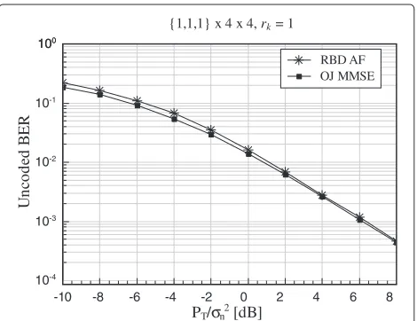
zero mean, unit variance complex Gaussian variables. First, in Figure 2, we compare the bit error rate (BER) performance of RBD AF and OJ MMSE under the assump-tion used in [14] that all UTs are equipped with only one antenna. The system antenna configuration is {1, 1, 1} × 4×4, i.e, there areK = 3 UTs in the system equipped with single antenna each, there are MR = 4 antennas
at the RN and MB = 4 antennas at the BS. Data are
uncoded and mapped using quadrature amplitude mod-ulation (4QAM). As we can see from the figure, the OJ MMSE algorithm that jointly optimizes the MIMO processing matrices at the BS and RN has only slight advantage over RBD AF at low SNRs. At high SNRs the difference between RBD AF and OJ MMSE is negligible.
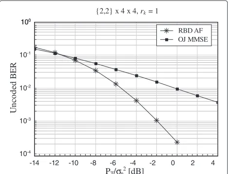
However, if we consider UTs equipped with multiple antennas then the RBD AF algorithm gains significantly over OJ MMSE. In Figure 3, we consider a system with the antenna configuration {2, 2} ×4 ×4, where the BS
{1,1,1} x 4 x 4, rk = 1
Un
co
d
ed
B
E
R
10-4
10-3
10-2
10-1
100
100
PT/σn2 [dB]
-10 -8 -6 -4 -2 0 2 4 6 8 RBD AF OJ MMSE
{2,2} x 4 x 4, rk = 1
U
n
co
de
d B
E
R
10-4
10-3
10-2
10-1
100
100
PT/σn2 [dB]
-14 -12 -10 -8 -6 -4 -2 0 2 4 RBD AF OJ MMSE
Figure 3BER performance of RBD AF and OJ MMSE system with antenna configuration{2, 2} ×4×4.RBD AF system transmits one data stream per UT using 4QAM and OJ MMSE transmits two data streams per UT using BPSK.
is transmitting one data stream per UT using the 4QAM modulation. In order to keep the comparison fair, in case of OJ MMSE we have two data streams per UT modu-lated using binary phase shift keying (BPSK). The RBD AF algorithm extracts higher array and diversity gains than OJ MMSE.
In Figure 4, we compare the performance of RBD AF algorithm and a system using hard decision DF relaying in an overloaded system, i.e., the system where the total number of antennas at the UTs is greater than the number of antennas at the RN. In case of DF system we use again the RBD algorithm to design the MIMO precoding matrix at the RN. However, we omit the influence of the additive noise at the input of the RN antenna array. The DF system has slightly higher spatial processing gains, and an SNR gain over RBD AF of around 3dB at BER=10−3.
Conclusions
In this article, we investigated a two-hop communica-tion from BS to the UTs over one RN. We derived the MIMO processing matrices at the BS, RN and the UTs using only local CSI. In order to be able to design the spa-tial processing matrices at the transmitter and the receiver independently, the transmit MIMO processing matrices are designed assuming only eigenmode decomposition at the receiver, regardless of the actual spatial processing used at the receiver. This is the worst case assumption as only the transmitter would have to deal with the noise and spatial interference. The emphasis is on the design of the MIMO precoding matrix at the relay as it has to process noise and interference on the first and the second hop at the same time. The MU MIMO precoding matrix at the
{2,2,2} x 4 x 4, rk = 1
Un
co
d
ed
B
E
R
10-4
10-3
10-2
10-1
100
100
PT/σn2 [dB]
-10 -8 -6 -4 -2 0 2 4 6 RBD AF
Hard DF
Figure 4BER performance of RBD AF and hard decision DF system with antenna configuration{2, 2, 2} ×4×4.There is one data stream per UT.
relay is designed using a criterion which minimizes the MU interference while at the same time tries to exploit as much as possible of the available UT spatial process-ing gains. In our simulations, we have shown that the proposed system has the negligible performance loss com-pared to the system that iteratively and jointly optimizes MIMO processing matrices at the BS and at the RN, and around 3 dB SNR loss at the BER of interest compared to the system that is using hard decision DF relaying.
Competing interests
The authors declare that they have no competing interests.
Acknowledgements
This article was supported by the Serbian Ministry of Education and Science (projects III44006 and TR32023).
Author details
1Department of Telecommunications, Faculty of Electronic Engineering, University of Nis, Aleksandra Medvedeva 14, 18000 Niˇs, Serbia.2State University of Novi Pazar, Vuka Karadzica bb, 36300 Novi Pazar, Serbia.3Faculty of Technical Sciences, University of Priˇstina, Knjaza Milosa 7, 38220 Kosovska Mitrovica, Serbia.4Faculty of Natural Sciences and Mathematics, University of Priˇstina, Lole Ribara 29, 38300 Kosovska Mitrovica, Serbia.5Faculty of Economics, University of Priˇstina, Kolasinska 156, 38220 Kosovska Mitrovica, Serbia.
Received: 6 July 2011 Accepted: 16 July 2012 Published: 28 August 2012
References
1. N Jindal, A Goldsmith, Dirty-paper coding versus TDMA for MIMO broadcast channels. IEEE Trans. Inf. Theory.51(5), 1783–1794 (2005) 2. E van der Meulen, Transmission of information in a t-terminal discrete
memoryless channel. Technical Report, Department of Statistics, University of California, Berkeley, (1968)
3. T Cover, A Gamal, Capacity theorems for the relay channel. IEEE Trans. Inf. Theory.28, 572–584 (1979)
4. A Sendonaris, E Erkip, B Aazhang, User cooperation diversity-part I and II. IEEE Trans. Commun.51(5), 1927–1948 (2003)
DD ˆA˘a Falconer, GP ˆA˘a Fettweis, Relay-based deployment concepts for wireless and mobile broadband radio. IEEE Commun. Mag.42(5), 80–89 (2004)
6. X Tang, Y Hua, Optimal design of non-regenerative MIMO wireless relays. IEEE Trans. Wirel. Commun.6(4), 1398–1407 (2007)
7. O Munoz-Medina, J Vidal, A Agustin, Linear transceiver design in nonregenerative relays with channel state information. IEEE Trans. Signal Process.55(6), 2593–2604 (2007)
8. Z Fang, Y Hua, J Koshy, Joint source and relay optimization for a non-regenerative MIMO relay. inProceedings of the IEEE Workshop on Sensor Array and Multi-Channel Signal Processing(Waltham, WA, 2006) 9. W Guan, H Luo, Joint MMSE transceiver design in non-regenerative MIMO
relay system. IEEE Commun. Lett.12(7), 517–519 (2008) 10. Y Rong, X Tang, Y Hua, A unified framework for optimizing linear
non-degenerative multicarrier MIMO relay communication systems. IEEE Trans. Signal Process.57(12), 4837–4851 (2009)
11. C Chae, T Tang, R Heath, S Cho, MIMO relaying with linear processing for multiuser transmission in fixed relay networks. IEEE Trans. Signal Process. 56(2), 727–738 (2008)
12. Y Yu, Y Hua, Power allocation for a MIMO relay system with multiple-antenna users. IEEE Trans. Signal Process.58(5), 2823–2835 (2010)
13. C Esli, A Wittneben, Multiuser MIMO two-way relaying for cellular communications. inProc. IEEE International Symposium on Personal, Indoor and Mobile Radio Communications (PIMRC)(Cannes, France, September 2008)
14. G Li, Y Wang, T Wu, J Huang, Joint linear filter design in multi-user cooperative non-degenerative MIMO relay systems. EURASIP J. Wirel. Commun. Netw.2009(2) (2009)
15. J Axnas (ed.), D2.10 Final report on identified RI key technologies, system concept, and their assessment. Technical Report IST-2003-507581 WINNER, IST WINNER, December 2005
16. H Sampath, P Stoica, A Paulraj, Generalized linear precoder and decoder design for MIMO channels using the weighted MMSE criterion. IEEE Trans. Commun.49(12), 2198–2206 (2001)
17. A Scaglione, P Stoica, S Barbarossa, G Giannakis, H Sampath, Optimal designs for space-time linear precoders and decoders. IEEE Trans. Signal Process.50(5), 1051–1064 (2002)
doi:10.1186/1687-6180-2012-186
Cite this article as: Stefanovi´c et al.: Multi-user MIMO MMSE non-regenerative relaying using local channel state information.EURASIP Journal on Advances in Signal Processing20122012:186.
Submit your manuscript to a
journal and benefi t from:
7 Convenient online submission 7 Rigorous peer review
7 Immediate publication on acceptance 7 Open access: articles freely available online 7 High visibility within the fi eld
7 Retaining the copyright to your article