July, 1949
A
Magnetic
Digital
Storage -
System
By ANDREW D. BOOTH, Ph.D.*
D
ESCRIPTIONS. have appeared·'!of 8torage devices for use in. serial . operation ealculating machines, but in this country at least, little emphasis has been placed on the other possible type of
computmg sy~lem, namely, that
cmployin~ parallel operation. It is not proposed to give any discussion of computing IDflchines in this paper but for completeness it must 'be stated that in serlO.l operation machines,the digits of a number
be-come available, antI are used, 00 ...
a time starting usually from the
leBft significant, whereas in a parallel operation machine aU 'he dia-its of any number becohle avail-able at the same time.
. V\'ithout wishing to become con-troversial, it mtly be remarked that von Neumann, who was the origina-tor of many of the current ideas on calculating machines, has aban-doned the serial operation machine ill favour of its parallel operation
~ounterpart.
. . . . Iremena for a Stora •• Device In either type of . calculating 'machine the requirements of the storage device are similar, and are as follows:
.(1) .The storal'e .hou,Id be perma-nent If desired.
(2) The contents of
ui
y position must be erasible at will and capable of replacement by new data.(3) The volumetric efficiency " should be hi,h.
(4) The access and' replacement time of stored data should be small.
PIS':a. Ha.netlc Rate of dock pul.. tree k
of desiper. at about tb~ ,ame time, the sY¥ern to be described in this paper, however, is thought to be the first in aetua} operation ..
Prlttdp'" 01 the
Maanetk:
Memory Essentially, th4? stora.e' device consists of a'cylindrical drum coated .with permanent magnetic material and rotating UDder & series of read /record heads arranged along a 'g~erator of the' cylinder. In Fig. 1
HI-H. are a set of the3e heads.
All of the digits of any particular namber which is in binary form . (e.g., Wilkes'), are re('orderl and read off simultaneously by the heads.
AOTATfIfG DRUM Q.Oac AMPLIFIER
Q:)UNTlR
Suceeslive numbers are recorded . in sequence as the drwn. l"Otatee and to distinguish between them
an
extra track (Ho) is added which con-tain. a set. of equispae.ed positive " clock " pulses. ,
In
order j;o determine the positionof the first number it is neeessary to indicate the start of this clock pulse tr"ck. This could he done in various ways; for example, it might atart )1Jith a single negative pulle, or alternatively a separate track_ mil'ht contain a sin,le pulse to in-dicate the· zero position of the clock pulse track. In fact, it turns out' to be much simpler to leave a small gap, clear of any pulses, at the end of the clock pulse track, and to nile this as a zero indication. The general appearance of the magnetic 8ta~e of the clock pulse track is then
shown in Fig. 2. I - ,
In order tp go to any position on the drum and -to read or record there, all that is' necessary is to count from the zero position on the clock -track and to arrange tbat the counter emits & pulSE: when it reaches the gi ven position, A
schematic diagram of the "hole memory is given in Fig. 3.
The positive pulse input from the dock track head is amplified and sent to the binary counter C, wbicJt . is arranged to zero on receipt of' a pulse from the shaping circuit
con-tained in Ao. ..
The eonte.nts of C are (~o)np8red'
with the requirc-d memory location as shown by a set of position num-ber inputs; when the two numllE'rs The delay line storage device of
Wilkes' and the cathode-ray tube memory of Williams2
satisfy all of the above requirements except (1) and to a l,ess extent
(a,.
Either of thete devIces loses all its stored data· if a power supply 'failure oecqn. In addition, in the forms described by the authors, neither is directly suitable for a parallel <~ operation machine..IS.:a. Ich.matlc ofm....-tc ... r . . .
1tAO PULSE---+-t ....
':fh~. idea of u&ing the well known prmclples of magnetic sound' record-ing for the storaee of digital data teem. t? have o:,ccurred to a number /
• DIrector. JHrkbeck CoIl .. ", Electronic Computer ProJect, V18It1111 PrortllOl' of Pby~. Unlvuuty of PIUlbllqb, U.s.A.
238
STATIC D.C. L.£YEL
Fi,. , •. Olltpu~from common ,ate drcuih
PI,. 11. Gat. cfrcll.t
5'6M
2'7M
V.ML.6
\
~
Engineering
July. 1949r---~----~~~-.NItUT
-~---~
-COUN~
l[RO PUlSE
-GATE P\.UE
·A~·~~--~--~+---~~~-(FIA 10) • "(I!V\oo~,...",...,....----...
---...J
"7 220n. ~ 220.4: I
HI . ,,
--Itpcl5ITIONi __:~
NUMBI
INPUTS I I _ • I
--~
COUNTtR UNIT
FI.. It. Counter alMl coJncldelKe ... r
potI~le to ,enerate a gate signal whie& extends over one-hall of the output pulse only, and thus to select a positive or negative pulse corres-ponding to unity or zero. Most of
t~e published gate circuits have the disadvantage of placing the output on a " pedestal' as shown in Fig.
16, o! else of transmitting pulses of one sign only.
To remedy this defect the circuit of Fig. 17 was devised.
~n th~ absen~ of a gate ptdae the
tWlD triode grids act as diodes and
s~ort-ciJ:euit incoming signals of
either Blen to earth. On applying a large negative pulse to the two anodes the electroos
are
repelled to the cathodes and the resistance of ~he g.rid cir~u~ts ri ... abarply. If,I~ thiS condItion, a voltage varia-tion occurs on Cl it is transmitted viaC, to the flip-flop; in the absence of the gate pulse, however, nothing
~anea.
The Output Sta,e. .
This consists of the standard
c~thode-coupled toggle, .hoWD in
F1.r.
18.For reliable operation it was neces-sary to compensate the inductance of the relay coil, and the network
shown behaves like a pure resistanl"P. Conclusion
It
will be seen from the above ~ir ~uit descriptions and from the photograpb of Fiar. 8 that the8tor~e RYstem described in. this
paper is considerably more com-pact than any hitherto disclosed. Although in ita preaent form it is
8O~ewhat slow in operation :it i. qwte easy to speed up the rotatioa of the cyhnder and to record and read data at Rveral stations around the drum. In thi. way ayailahilify times of better than 1 millisecOnd could
be r~alised. Work is at preaent!ro.
ceedmg along theae lines an it appears that the neeeuary modifica-tions are trivial in nature.
. The author wi.he.
to
expre. hi.sl~cere thanks to
Dr.
Geoffrey Gee, Dlrector of Reaearcli, -.ud tothe
Board of the Briti.h Rubber
Pr0-ducers'.. Research Auoeiation fo~ 8upportm,( this work,
abd
allO toMl~.
x.
Sweetin,
andDr.
R.W.
'Williams for aailtance
in
eoft ..Itruction.
...
1 WI" aocJ 1leD'W'Iel ~ . . . DiJN'
20, lOS. (l~k •
• Willi . . . &Del Kw... J..-Ir .•.•. (Ia ... '
: . .r
•
July. 1949
FI,. II. c. .... r UI4 COIMId . . ce unit
COUNTER UNIT
VI-6. Ml6
tents and relay do not agree, how-ever, the coincidence valve con-ducts. Since the resistance of any coincidence valve is only about 7.KO, if at least one valve is conducting the potential at the common anode load cannot ri!e above 7 /57 x 120
==
15 volts, which is well below the cut-off of the first stage of V.. The second stage of. V. acts as an inver-tor and pulse shaper, since a sharp positive trigger pulse is reql.Jir~dfor the input pulse generator. V. generates a negative pulse of
220 volts amplitude. and 15 "sec. duration which il used to gate the outputa from the digit amplifi.ers into their respective ftip-flops.
The Input
Puue
Generator.Since the heads have an input
-20V. -20V.
.... 11. I ... pul . . . rat.r
---II',
.... II. ...Ia? I ... .,t .at.
tlectronic tmJineerirIJ'
impedance of less than :>.1 nand require pulse currents of 10-20 amps., a Special generator had to be desiped. Thyratron circuits· were tried, but were found to be un-reliable and liable to parasitic oscillation. Eventually the circuit shown in Fig. 12 "as devised and gives completely satisfactory results. In the present memory the record gate G. is a relay, but it would be simple to substitute an electronic element.
In
the absence of a ,ating pulse viaGo
the blocking OSCillator is held off by the hias. The tranl-former produces a pulse of leas than 1 "Iec. duration and the cathode follower transformer ena.bles the whole head array to be pulsed. The l"put Gate •.These. are constructed from relay elements and are shown in Fig. 18.
Each gate element con.ists of two
relay.
having two change-over con-tacts which are activated from· the main cinuita of the machine. When relay"1"
is operated the head is pulsed in the positive sense, and when relay HO'~ is operated in the nelatiTe sense._ he gate action iBOlatel the digit track amplifiers during pulsing, as
the stray pulse 'Which crosses the relay contacts due to capacitii.tive coupling does nbt effeCt the input transformers, which have extremely low input impedance.
TIte Dagit A mpli/ier3 .
These a-re perfectly straightfor-wa.rd
R...c
coupled amplifiers, again censtructed to give low gain below10 Kc / s. A typical circuit is shown
in Fig. 14,. .
The O"tput Gate.
. It i. desired to gate the amplifier output into a Sip-flop circuit at a given position only, the two possible amplifier output pulse shapes being shown in Fig. 15.
Since the clock pulse occurs at the origin in the above sketches, it is
237
COINCIDENCE UNIT
+200V +JOOV +JOOY +3OOY
VI-Us..
-JV -2V Y2 _ Po ..
... 14. T? . . . . 4 .... • m ...
•
CiATE INTERVAL
236
" •. t. O~ • . , tI •• 11 ... 1 , . ...
rec_'"
"'
..
...
,
f
l
.dronic
f
lllJineeri
l1lj
MI!(hanlul Connruct!OIl
A photOgfRph of thl' cylinder and ht'all as\t'Ulhly ill el""" In Fi,r. 8.
"01' ruallWIlHlliral n',lsonl it ... as
decided to have ~1 binary digit nUlllher!< lind to storl' 2~ such
qunnliht's. With the pa{'kinll gf
.so
diglts/in. Ilnd .'11l1rfare 5pt'ed of ~ft.
i
IW'I'" lhll resulted in It cylinder'J in. In diameter nnd 12 in. Ion, rotating al 9,000 r.p.lII. The rn •• ,
-mum waitmg lime lor feadiolt or
recording II ~ m.st''', and the mean
time 10 111.1('(':.
Thf" h('aJ,. shown in delail io
Fir> !). RI"f' mounted on a brau bar IUId are indi"iduaJly adjustable by means of a Simple S('few aMCmbly.
.""'<
·lOOV,July. 19-49
Coarse adjustment ,I> provided for
aligning the mnm IJar And the drum
~lIrfllCt:.
Circuit.
At the uu15et it can lJe stalclllhut nil relay.s art of the Slt'men.s high spet.i variety "'ilh Jt)oo .. lOO'Jl.~
coils, The measured 11I1IC of rlusur ..
(lr operatIon of tht'lil' is Ic~~ thM\
:! nLleC. Rela\'," lin' ,Ifilli'll In the
normal po~ltion.
The Clock Track Ampl,{lft.
Un this track it I~ nrccssary to re
prooul'c With :1(·t'lIrn(')" the libllrp
transition bt-tweell the two lurmllll! points In output \'olta~e silO" n III Fig, ti, !llld It wall .1,,'lded tli:ll II
!,und .. idth of at Icast :!OO Kc/s. waR
nce,led, The nmllhllf'r cirCUIt of
Fl •. IU fro"ed s.lequllte.
It '" il t~ notl~d that the ,ll"rlti
,'oupling and screen re81stor hy 1lU.s.~ tLine constants are 110 cho~n that
there is a Iterp ret..l'H"tion III gam
Ilt'low 10 ",1,'/5. Thl\ makt"S the Illllplifier \,f'ry mUl'h more stl\hle and
makes illh'r.st(lge decollphng un
-necessary. In partil·ular. ~c/s.pick.
lip and microphonic noi~e from V.
are imperct'ptlble. V, is bia.se<1
~Io'" cut-j)ff to en aLit the nOise
b.ck~oulI(l from the medium to be
clipped off. Thill i. ne<'easary, ,inet"
the ,.p .t tbe end of the dock puble
track (Fi •. 1) may (..'ont.,o a noise pul.se of .ufficient IImplitude to
tri • .rer the counter aftrr it haa been
lICt to r;ero.
The output of V, i, 'cd dir~tly
to the input of the binary counter
and a portion i, rectified by the IN84 ,umanium dIode and appliC'd U a oegAtive potentl.l to the Ilrit..l lea. of tbe blocking oscillator tube
V.. Thill keep, the l!ltlt'r from firing UDtil the dock pulse track .. ap is
reached, wben the chllrgt on C leaks
IIW.y via R. The firin.r of V. tendll
a pul.se via the output windina of T
to the grid load rcti,tor of the
counter. thu, .. uro-in.r" tbe latter.
Th~ CouPlt~r and Coi,..cid .. ,.cc Sell.n-. The counter used i. an ordinAry
ac.le-of-lwo circuit with buffer amplifier to remo"e unwanted
pulle •. ' The circuit constanu are
choaen 10 thllt the counter i.
nli-Able' up to 100 Kef •.
CO\fnUlr Unit \
It will be 'een from Fi,.
n
that when.Of
one of the eounter .tap. C .. i. io tbe .lIme.tate
("0" or "I") I.. itt ulOCiII.ted reby B., tbe potential 01 tbe ~d ot theCDn'n-poDdin, coincidmce v.lv(" f.U.
July, 1949
agree a pulse is emitted by a circuit. Normally this pulse opens a set of gates GIl-G.t, which allow the out-put pulses from the digit track heads lIt-lIo to set a series
of flip-flop storage elements
Fl-Fn to the digit pattern re-corded under the heaus in the given position. When it is desired to record in a given position a gatp. Go allows the aho"e coincidence pulse to trigger a "record pulse" generator which sends either posi-five (" 1") or negative (" t) " ) pulses, via the input gates Gl-(; .. , to the heads. It should be noted
~hat prior to the record operation the input gate "ill havel lleen set to
" 0" or " 1 ,. positions from digit input leads, and that the nature (f
the storage IS such that the inJ)ut data. automatically . erases th:1t alrcady present.
In the present memory, inteJ.<ic(1 for use with A.R.C. (Automat.ic Relay Computer), thc input gates
Gl-G., the record gate Go and part
of the count.er-coincidelll't: circuit are relJly elements, ann the output flip-flops set relays to operate the remainder of the machine.
The Ma,netlc Circuit
While many highly specialised magnetic recording medIa exist, these are at prelent difficult to obtain in suitable form, and it was decided to use 8 thin plating of
elec-trolytic nickel. Although the mag-netic properties of thi~ seem to leave much to be desired, the medium i~
quite good enough for the purpose in hand. In the finut design a plated layer between .0005 in. ,and
.001 in. in thi<>kness was used. Extensive experiments showed that up to 100 digits / in. could be re-corded, hut for safety it was decided to use only a 50 digits / in. packing
ztJ
-
-t"
'
~~.
2000 TURNS O'02J
:~
GAPPI.. S.
SI,,".
wi,.. he ...Fl •• ,. Out~ut yelta . . fro.", ~I ... wlr . . .
3S this allowed for considerable
variation. in head ('onstruction. The surface speed of the drum was
25 ft. / 8ec. .
The first models of the recording heads were of the form shown in }"ig. '40.
Single laminations of .O'A) in. sili· con iron were used and the heads were 'run in contact with the cylinder as sh~wD. .IT sing 2,000
turns on the ma,netising coils it was found that the shortest recording pulse whieh could be used was 85
lisec. This left much to be desired
.and further experiments were
instituted.
About this tim~ Dr. Julian
Bigelow* suggested usiJ!g a single, very fine wire as recording head.
This was to be mounted in· close proximity to the drum surface and pulsed with a current of hetween 10
and 50 amps. Since the current flows for con~iderablv less than 1 lisee. this does not· damage the wire. It can he :ahown that if the input pulse is short enough for the
recording medium not to move
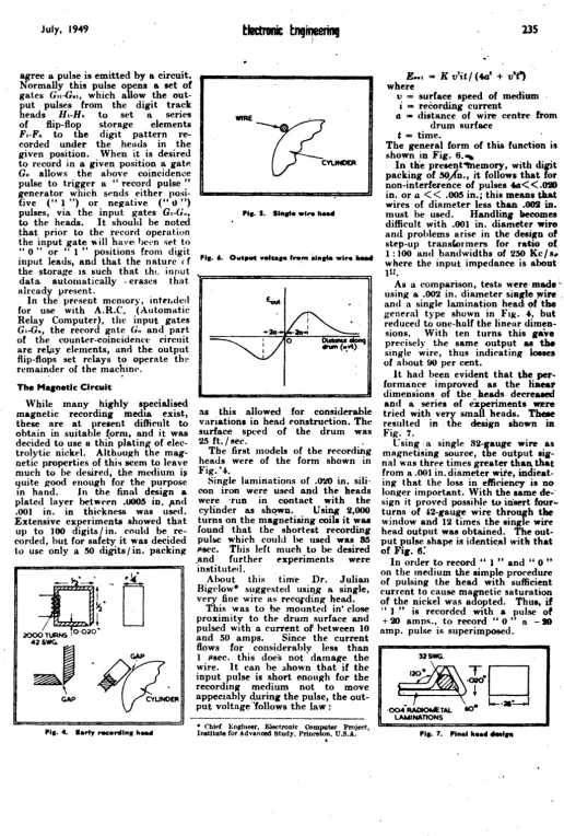
appeciably during the pulse, the out-put voltage > 'follows the law:
• Cblt'f En~llIeer, Electroulc Computer Project, Inatltute for Advanced Study, Princeton, U.S.A .
.
E.uc
=K v'it/
(401+
v-"
where235
v = surface speed of medium i-recording current
4 ~ distance of wire centre trom drum surf~e
t
= time.The general form of this function is shown in Fig.
6.,
In tlie preaent4fnemory, with digit packing of ~)'n., it follows that for non-interference of pulses
.f.G< <.010
in. or a< <
.005 in.; this meaDSthat
wires· of diameter less than .002 in. must be used. Handling becomes difficult with .001 in. diameter wire and problems arise in the design o' step-up transwl"mers for ratio of
1 : 100 and bandwidths of 250 Kc / 84' where the input impedance is about IU.
As a comparison, tests were·made~· using a. .002 in. diameter siRl'le JVire . and a single lamination head ~f the general type shown in }"II(. 4, but reduced to one-half the linear
dimen-sions. With ten turns this gave precisely the same output as the single wire, thus indicating losses of about 90 per cent.
It had been evident that
the
per ..formance improved as the
liaear
dimensions of the heads. decreaaed and a. series of exrriments ~re tried with very smal heads.
Thele
resulted in. the design shown iu Fig. 7.
L sing' a single 82-gauge wire as magnetising source, the output lia-nal was three times greater than. that from a ~OOI in. diameter wire, indieat-ing tha.t the loss in efficiency is no longer important. With the same de~<
sign it proved possihle to insert four-turns of -'2-Kauge wire through
the
window and 12 times the 8ingle wire head output was obtained. The out-put pulse shape is identic.al with that of
Fir.
6:
In order to record " 1 " and " 0 "
on the medium the simple procedure of pulsing the head with sufficient current to cause magnetic saturation of the nickel was adopted. Thus,
if
rc 1 " is recorded with a pulse of
+20 amps., to record" 0" n - . amp. pulse is superimposed.
32SWG.
~'~fll
~.
t:;d
'OO4~TAL to LAMINATIONS