I
GENERAL
REFERENCE
M A N U A L
CONTENTS
1. FOREWORD... 1-1
2. GENERAL DESCRIPTION ... 2-1 Concept of Design ... 2-2 Features ... 2-2 Univac Services ... ... 2-3
3. COMPONENT DESCRIPTION ... 3-1 Centra I Processor ... ... ... 3-1 UNISERVO Tape Units ... 3-2 High-Speed Reader ... 3-5 Card Punch Unit ... 3-5 High-Speed Printer ... 3-6 Automatic Program Interrupt ... 3-6
4. APPLICATIONS FOR THE UNIVAC 1050 SySTEM... 4-1 Card-to-Tape ... ... ... ... .... ... 4-1 Tape-to-Printer ... ... ... ... ... ... 4-3 Tape-to-Card .... ... ... ... ... ... ... ... 4-6 Concurrent Program Operation ... 4-8
6. PROGRAM OPERATION ON UNIVAC 1050 SySTEM... 6-1 Coding Example ... 6-1 Normal Computer Operation ... 6-9 PAL Assembly Operating Procedure (Tape System)... 6-11 Special Computer Operation ... 6-12 7. AUTOMATIC PROGRAM INTERRUPT... 7-1
Summary ... 7-2 Generation of Interrupt Requests ... 7-2 Interrupt Inhibit ... 7-3 8. PERIPHERAL UNIT OPERATION... 8-1 High-Speed Reader Control Panel ... 8-2 Card Punch Unit Control Panel. .... ... ... ... ... ... ... ... ... 8-3 High-Speed Printer Control Panel ... 8-4 UNISERVO IliA and IIIC Tape Units Control Panel... 8-6 9. INSTALLATION SPECiFiCATIONS... 9-1
APPENDICES: A. Octal-Decimal Conversion Table ... A-I B. Indicators ... B-1
Figure 2-1. Figure 3-1. Figure 4-1. Figure 4-2. Figure 4-3. Figure 5-1. Figure 5-2. Figure 5-3. Figure 5-4. Figure 6-1. Figure 6-2. Figure 6-3. Figure 6-4. Figure 6-5. Figure 8-1. Figure 8-2. Figure 8-3. Figure 8-4.
Block Diagram of a Typical System ... Storage Assignment Chart
Card to Tape Conversion Tape to Printer Operation. Tape to Card Conversion .... Standard 1050 Configurations PAL Coding Form. ... ... . PAL 80-Column Source Card .. PAL gO-Column Source Card.
Input Card Format for Sample Problem. Section Total Cards for Sample Problem .. Sample Problem Block Chart.
Sample Problem Coding .. Central Processor Control Panel ... High-Speed Reader Control Panel .. Card Punch Unit Control Panel . High-Speed Printer Control Panel.
UNISERVO III A and III C Tape Units Control Panel ..
ILLUSTRATIONS
iv
Table 5-1. Table 5-2. Table 5-3. Table 5-4. Table 5-5. Table 5-6.
UNIVAC 1050 System Character Set Suggested Standard Equal ity Statements .. Mnemonic Operations Ordered by Operation Code Mnemonic Operations Ordered Alphabetically Abbreviations in Writing Instructions .. Instruction Repertoi re ... .
5-8
5-9
5-12 5-12 5-13 5-14
1. FOREWORD
This manual introduces the UNIVAC® 1050 Sys-tem and describes the sysSys-tem's hardware and software aspects. Information concerning the sys-tem's uses, programming, operation and installa-tion is also included. Moreover, the manual relates the approach to the design of the system and the provisions Sperry Rand Univac has made for its efficient installation in office, plant or laboratory. It also specifies what Univac will do to help the user put the UNIVAC 1050 System into produc-tive use.
Because the manual will reach a varied audience, an attempt has been made to provide information of interest to users of business and scientific
com-1. FOREWORD
puting systems; operators and supervisors of punched card equipment; programmers of small to large scale equipment; and managers of re-search, engineering, financial, production and mar-keting departments.
2. GENERAL DESCRIPTION
The UNIVAC 1050 System may be used as a subsystem or auxiliary device to large scale equip-ment such as the UNIVAC III, 490, or 1107 Sys-tems. In addition, the UNIVAC 1050 System can be effectively utilized in a remote plant or branch office location as an integral part of a centralized electronic data processing system.
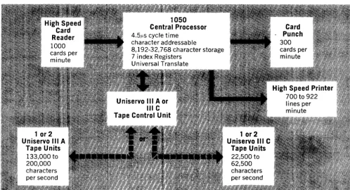
The UNIVAC 1050 System consists of a Central Processor and a UNISERVO tape handling unit
4.5.us cycle time
2. GENERAL DESCRIPTION
and any of the following: a High Speed Printer, a High Speed Card Reader, a Card Punch Unit, and a second UNISERVO tape handling unit. The UNISERVO tape handling units may be either UNISERVO III A units for the UNIVAC com-patible satellite system or UNISERVO III C units for the IBM compatible satellite system, but not one of each. Standard configurations and software available for each are shown in section 5 (Figure 5-1).
character addressable
8,192-32,768 character storage
7 index Registers
1 or 2 Uniservo III A
Tape Units
133,000 to 200,000 characters per second
Universal Translate
1 or 2 Uniservo III C
Tape Units
22,500 to 62,500 characters per second
2-2
CONCEPT OF DESIGN
The design objective of the UNIVAC 1050 System was to provide a system to relieve large scale systems of the burden of housekeeping func-tions detracting from the critically important tasks of computation, analysis, and the preparation of management reports. Included among these house-keeping or auxiliary functions are the necessary operations of converting information from punched cards to magnetic tape, magnetic tape to punched cards, or magnetic tape to printed hard copies, and the maintenance of master record tapes.
The UN IV AC 1050 System can accept many dif-ferent codes and convert them efficiently. More-over, the satellite system can be called upon to operate at speeds commensurate with the powerful large scale system's demands and at the same time, perform highly complex editing operations. Fur-thermore, the nature of the attendant functions peculiar to each installation demand a custom con-figuration of the satellite system and thus modu-larity is a key factor in dictating the design of the UNIVAC 1050 System.
With the experience and ingenuity that made UNIVAC the first name in automatic data-process-ing systems, the UNIV AC 1050 System was designed with features that surpassed these strin-gent requirements making it the foremost satellite computing system available.
FEATURES
All of the features listed below are standard for the UNIVAC 1050 System except for the expanda-bility of memory. This allows for a high degree of cross-system compatibility.
A HIGH DEGREE OF COMPATIBILITY WITH LARGE SCALE SYSTEMS
The UNIVAC 1050 System can accept tapes fronl or prepare tape for: the UNIVAC III, 490, and 1107 Systems, or the IBM 1410, 705, 7070, 7080, and 7090 System. The UNIVAC 1050 System can read or punch any card code including straight binary code. The system can automatically trans-late from standard 80-column Hollerith code to the internal UNIVAC 1050 code, and vice versa. The system has an instruction that automatically trans-lates a block of data from anyone 6-bit code to any other 6-bit code.
HIGH RATES OF SPEED ON ALL PERIPHERAL UNITS
High-Speed Reader - 1,000 cards per minute
Card Punch Unit - 300 cards per minute
High-Speed Printer - 700-922 lines per minute
IlIA Tape Transfer - 100,000-133,000
charac-Rate (UNIVAC ters per second
Mode) 150,000-200,000 digits
per second
III C Tape Transfer - 22,500 or 62,500
charac-Rate (IBM Mode) ters per second
FAST INTERNAL STORAGE SPEED
The core storage of the UNIVAC 1050 System has a cycle time of 4.5 microseconds.
PROGRAMMING SIMPLICITY
A joint software and hardware development has resulted in an efficient programming system which takes full advantage of the powerful instruction repertoire. The software package contains:
PAL Assembler
An easy to use, easy to learn assembly system which includes input-output macro-instructions, diagnostic macro-instructions, as well as special-izable precoded input-output routines.
Operator
An integrated Co-ordination Routine and Relo-catable Relative Loader which allows the oper-ator to communicate with the system and to load and start programs that will operate independ-ently or concurrindepend-ently. The Co-ordination Routine assures effective utilization of the various input-output channels.
Source Code Librarian
A routine which facilitates the maintenance of a tape file of source programs.
Patch Assembler
A routine which allows the user to make source code changes, insertions and deletions to the object code.
I nput-Output Library
A complete set of input-output routines which can be specialized and incorporated with the users program at assembly time.
Regent
A report program generator which automati-cally translates report requirements into ma-chine language programs.
Uti lity Routines
A standard set of Utility Routines will be pro-vided as part of the UNIVAC 1050 System soft-ware package. These routines will allow the user to perform simple card-to-tape, tape-to-printer and tape-to-card operations. Standard data tape conventions will be used.
All of the above software aids reduce over-all pro-gram preparation time.
MODULAR DESIGN
The magnetic core storage is available in modules of 4096 six-bit alphanumeric characters and may be expanded from a minimum of two (8192 char-acters) to a maximum of eight modules with a total capacity of 32,768 alphanumeric characters.
INDEX REGISTERS
Seven built-in index registers are included for pro-gramming ease and processing efficiency.
VARIABLE FIELD LENGTH
Data fields are variable in length to enable flexible and efficient use of the storage and the data-proc-essing capacity of the system.
FLEXIBLE USE OF STORAGE
Any area of main storage can be used for input-output buffer storage. Also, blocks of input or
output data can be spe~dily transferred from one
section of storage to another.
EDITING EFFICIENCY
Editing instructions are provided for automati-cally and efficiently inserting punctuation marks, symbols, and characters and suppressing non-significant commas and zeros in an output field. An editing pattern may be established for use on successive output fields.
COMPREHENSIVE INSTRUCTION REPERTOIRE
The system contains a complete and comprehensive instruction repertoire with commands for per-forming both binary and decimal arithmetic operations, including decimal multiplication and division.
AUTOMATIC PROGRAM INTERRUPT
The system contains an interrupt network which facilitates maximum utilization of the UNIVAC 1050 peripheral devices. Interrupts also indicate to the user when decimal overflow and improper division is attempted. Central Processor error faults and emergency conditions also cause automatic interrupt so that a possible computer malfunction will be detected.
OPERATING SIMPLICITY
The operator's tasks can be performed quickly and easily. The system is designed to operate automati-cally with a minimum of monitoring.
UNIVAC SERVICES
In support of its design, production, and distribu-tion of data-processing systems, Sperry Rand Univac supplies a wide range of services to ensure the effective and profitable use of each system. To begin with, an information service is maintained to afford accurate and complete reference material for all users. This manual represents the initial phase of the service which will be extended through forthcoming manuals. To reinforce these efforts, Univac representatives will obtain answers to questions not anticipated in the reference manuals.
Univac provides consultant services for systems analysis and programming. The scope of these services begins with feasibility studies, and re-lated systems and cost analyses. It continues with system and subsystem design, including card and tape file layout, printed report formatting, and over-all system block diagramming. Also included are: consultation on personnel planning and peri-pheral equipment and supplies; selection of ap-propriate software to use in program preparation; provision for necessary training and programming aids; and technical guidance in the writing and checkout of initial programs. In addition, the services provide recommendations for the estab-lishment of good practices for programming and operating procedures.
mar-2-4
gins that enable them to operate correctly under adverse conditions. Extensive operation and test-ing have proven the reliability inherent in the design of each input-output device. The basic printer design, for example, has been proven by years of mass-production printing on the UNIVAC I, UNIVAC II, UNIVAC Solid-State and UNIVAC LARC Systems. The printer of the 1050 System is a high-performance device with a reliability matching that of the electronic circuits in the system.
To ensure that reliability is kept up to its initial high level, a competent staff of Univac service
engineers is available to service the 1050 System. Univac service engineers follow a strict preven-tive-maintenance program designed to remove the cause of a potential failure in the system before it develops. Periodically the system is thoroughly tested and serviced. Marginally operating compo-nents are replaced before they can cause a failure. Additionally, between periodic systems tests, the user himself may test the performance of the sys-tem. A complete set of programs is furnished for this purpose.
3. COMPONENT DESCRIPTION
The system consists of a Central Processor with
CENTRAL PROCESSOR
magnetic core storage, and may include a High-Speed Reader, a Card Punch Unit, a High-High-Speed Printer, and one or two tape units (either UNI-SERVO III A or UNIUNI-SERVO III C).
The basic UNIVAC 1050 System has been de-signed for future expansion to meet the con-stantly growing data-processing requirements of modern business. The memory capacity of the System can be expanded from two to eight memory modules.
The expansion inherent in the UNIVAC 1050 Sys-tem is achieved without in any way compromising the basic design. All systems are capable of on-site expansion to any larger configuration (up to the maximum) with a minimum of interruption and elapsed time. Expanding the storage capacity, for example, involves little more than plugging in additional printed-circuit cards and core-storage units.
UP-2590
The Central Processor houses the control, arithme-tic, storage, indexing, and other processing com-ponents which, operating at program direction, perform the input-output, logical and arithmetic functions of the system.
Storage Capacity
The UNIVAC 1050 System employs an expandable magnetic core storage capable of receiving or dispensing data at a rate of one alphanumeric character every 4.5 microseconds. Core storage is divided into modules, each having a capacity of 4096 six-bit alphanumeric characters, each of which is addressable.
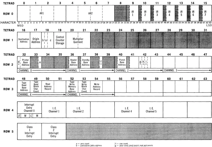
Core storage is character addressable (positions 0-32,767). For ease in presentations and illustra-tion, this storage can be considered as rows of information with 64 positions (columns) in each row. The first row (row 0) in memory contains positions 0-63; the second row 64-127, etc.
Tetrads
The first 256 characters (4 rows) of storage are grouped into 64 fields of 4 characters each. These
fields, called Tetrads can be addressed as four
character groups. They are used as Arithmetic Registers, Index Registers, and fields specifying origins and destinations of data for input-output operations. Individual characters of a Tetrad may also be addressed. See Figure 3-1 for special as-signments.
Arithmetic Registers
Two 16-character Arithmetic Registers are pro-vided to reduce the necessity of storing intermedi-ate results. The Arithmetic Registers can be ad-dressed as AR1 or AR2; 4-character groups within an AR can be addressed as Tetrads ( 0-7) or a single character within an AR can be addressed as a storage position (00-31).
Index Registers
There are seven Index Registers. The low order
three characters of Tetrads ~-15 are used to store
the Index Registers. Index Register 1 is contained in Tetrad 9, Index Register 2 in Tetrad 10, ... In-dex Regi~ter 7 in Tetrad 15.
Input-Output Channels
The core storage serves as the main communication link between the Central Processor circuitry and
the input-output control units. It is a key part of a
balanced system of internal communication and control that enables input and output operations to proceed continuously, at full speed, simultane-ously with the processing of data. There are five assigned input-output channels which are used to
connect the input-output control units to the core storage and the input-output controls in the Cen-tral Processor. A list of the assigned channels and their allocations are:
CHANNEL INPUT-OUTPUT
0 Printer
1 Card Reader
2 Card Punch
4 Magnetic Tape Read
5 Magnetic Tape Write
Associated with each of the Input-Output chan-nels is a fixed storage area each consisting of a group of four consecutive Tetrads (see storage assignment, Figure 3-1). These areas contain in-formation for the control of the peripheral devices such as the number of lines of paper advance before the next line is printed, the location where information from the card reader is to be sent, and so on.
There are no fixed storage areas reserved for input-output data. Data read from a card or data to be punched on a card or printed on a line can be stored in any area of the storage that is not being used for other purposes. The only restriction is that the beginning of each card input or output area must coincide with the beginning of a 64-character row of the storage.
Also associated with each channel is an interrupt entry. The information in this area is necessary for the optimum operation of the various peri-pheral devices and will be explained in a later sec-tion of the manual.
UNISERVO TAPE UNITS
TETRAD
ROW 0
CHARACTER
TETRAD
ROW 1
TETRAD
ROW 2
TETRAD
ROW 3
ROW 4
ROW 5
0 2 3
I
I
ARI
I
o 1 2 1011 12 1
MSD
16 17 18 19
Origin I
Destination blal c
I
Counter Control Address AddressI I Storage
48 49 Tape Tape Read Read Base Block Address Count Char.
CHANNEL 4
HI
Interrupt Entry Channel 0
M
I ci
Class 1 Interrupt
Entry M
I
I34 35
50 51
Read Address
Record
I.E. Channell
Class
2
Interrupt Entry
4 5 6 7 8 9 10 11 12 13 14 15
IR
AR2 7
23 24 25 26 2728 29 30 31 32 33 34 3536 37 38 39 40 41 42 43 44 45 46 47 4849 50 5152 53 54 55 56 57 58 5960 61 62 63
20 21 22
36 38
52 53 54
Tape Tape
Write Write Write Memory Block Address
Base Char. Record Address Count
CHANNEL 5
I. E. Channel 2
a = zero count
b = translation table address c = block transfer count *d = character count
e = I ine advance count
23 24 25 26 27
41 42 43
55 56 57 58 59
I. E. I.E.
Channel 4 Channel 5
*f = row count
*g = hole count (post-punch read and punch) *h = hole count (wait and pre-punch)
* i = row count (punch) *used only by control units
Figure 3-1. Storage Assignment Chart.
LSD
28 29 30 31
44 45 46 47
to appropriate tape formats for recording. tape units compatible with large scale UNIVAC
Systems, while the UNISERVO III C units are
compatible with IBM Systems.
There is a Control Unit for either type of tape unit which accepts, interprets and acts upon con-trol signals, instructions, and data from the Cen-tral Processor. The Control Unit converts the data
The Control Unit indicates its status and the status of the available tape units to the computer through testable indicators. These indicators are explained in a later section.
CHARACTERISTICS TAPE SPEED
PULSE DENSITY SPACE BETWEEN
BLOCKS
DATA TRANSMISSION RATE
REWIND TIME REVERSAL TIME STOP/START TIME
(DIFFERENT SERVOS) STOP/START TIME
(SAME SERVO) READ/WRITE
OPERATION TAPE WIDTH TAPE BASE
THICKNESS TAPE LENGTH
REEL CHANGE TIME CHANNELS ON TAPE
FILE PROTECTION WRITE CHECKING
The following table presents the characteristics of the two different types of tape units:
UNISERVO III A TAPE UNIT UNISERVO III C TAPE UNIT 100 inches per second 112.5 inches per second
1000 pulses per inch 200 and 556 pulses per inch
0.75 inch 0.75 inch
133 KC Max (Alphanumeric) 22.5 KC and 62.5 KC 200 KC Max (Numeric)
100 KC (111,490,1107 compatible)
125 Seconds For Tape 87 Seconds For Tape 3500 Feet In Length 2400 Feet In Length
600 Milliseconds
7.8 Milliseconds 10.2 Milliseconds 13.2 Milliseconds 14.2 Milliseconds
Reading in forward and backward Reading and writing operations directions; writing in the forward proceed in the forward direction only direction only
liz inch
0.001 inch 0.0015 inch 7.5%
600 feet 2400 feet
1800 feet 3500 feet
30 Seconds
9 Channels- 7
channels-2 Parity bits for each 6 data, 1 parity 3 frames
7 channels-6 data, 1 parity
When the Write Enable ring is
inserted, a write operation can be effected This ensures that no errors or bad
HIGH-SPEED READER
CHARACTERISTICS
CARDS PER MINUTE CAPACITY OF INPUT
HOPPER
NUMBER OF OUTPUT STACKERS
CAPACITY OF EACH OUTPUT STACKER
1000
3000 STANDARD-THICKNESS CARDS
3
1000 STANDARD-THICKNESS CARDS
The High-Speed Reader senses SO- or 90-column cards at a maximum rate of 1000 cards per min-ute. Sensing is accomplished by highly reliable solar-cells. Before each read operation, all of these cells are automatically checked. This feature in-sures accuracy in the information transmitted to the Central Processor.
Ninety column cards are placed in the input hop-per face up with the row 9 edge leading; SO-column cards are placed face down with the row 9 edge leading.
The maximum reading rate is easily achieved with the aid of the interrupt network. A program inter-rupt occurs every card cycle (60 milliseconds), unless inhibited. Card feed orders are issued at this point, if possible, maintaining the maximum rate. Storage access times required are less than 5 milliseconds for the SO-column system and less than 3.S milliseconds for the 90-column system; leaving most of card cycle time available for proc-essing.
The input card hopper has a capacity of 3000 standard-thickness cards. Small or large quanti-ties of cards can be easily IQaded while the reader is operating. There are three output stackers each with a capacity of 1000 standard-thickness cards. When the first stacker is full, card output is auto-matically switched to the second stacker. When the operator has removed the cards from the first stacker and depressed the stacker reset button,
UP-2590
card output is switched back to the first stacker. Normally, the third stacker serves as a reject stacker and receives cards following the detection of an error.
As a customer option, the card reader can be equipped to read stub cards (51 column size on SO column reader or 29/5S column size on 90 column reader) at 1000 cards per minute, as well as full-size cards. The stub cards are commonly used in billing, inventory control and many other applications. The card reader can also be equipped, as a customer option, to read cards of post-card thickness, as well as standard-thickness cards. Cards may be perforated to allow for subsequent separation or scored to allow for subsequent fold-ing.
CARD PUNCH UNIT
CHARACTERISTICS
CARDS PER MINUTE CAPACITY OF INPUT
HOPPER
NUMBER OF OUTPUT STACKERS
CAPACITY OF EACH OUTPUT STACKER
300
1000 STANDARD-TH ICKNESS CARDS
2
850 STANDARD-THICKNESS CARDS
The Card Punch Unit can punch SO-column or 90-column cards at a maximum rate of 300 cards per minute. Under control of the processor pro-grams, cards may be selectively punched or se-lected cards may be advanced without punching. There are four stations in the card transport sys-tem; two wait stations, a punch station and a post-punch check-read station. The post-punch check-read station enables a positive hole-count check to be made of data that was previously punched.
Maximum rates can easily be attained as the punch causes a program interrupt at the
tion of its cycle, whereupon another punch order can be issued.
The card input hopper has a capacity of 1000 standard-thickness cards, which are placed in the hopper in the same manner as in the card reader. Small or large quantities of cards can be easily loaded while the Punch Unit is operating. There are two output stackers each with a capacity of 850 standard-thickness cards. Normally cards are directed to only one of the stackers. The second stacker functions as a reject stacker that receives cards following the detection of an error in the Card Punch Unit.
HIGH-SPEED PRINTER
CHARACTERISTICS
LINES PER MINUTE 700 TO 922 (SINGLE-SPACED,
ALPHANUMERIC)
CHARACTERS PER LINE 128
LINES PER INCH 6 OR 8 AT OPTION
(VERTICAL) OF OPERATOR
CHARACTERS PER INCH 10 (HOR IZONTAL)
NUMBER OF PRINTABLE 63 CHARACTERS
CONTINUOUS PAPER- 20 INCHES PER
FEED RATE SECOND
PAPER STOCK ANY SPROCKET-FED PAPER, 4 TO 22 INCHES WIDE, UP TO AND INCLUDING CARD STOCK-THICK-NESS, EITHER BLANK OR PREPRINTED FORMS
COPIES AN ORIGINAL AND AT
LEAST FIVE CARBON COPIES
A buffered unit, the High-Speed Printer operates under control of the processor program producing high-quality multiple-copy records in a completely edited format. At the option of the program, either 128-character full lines or 64-character half lines may be printed. The paper can be fed in steps for single-line spacing or fast fed for mUltiple-line spacing under control of the pro-gram. With single-line spacing, data may be printed at a rate ranging from 700 to 922 lines per minute depending upon the range of characters employed by the processor program. Maximum rates can easily be attained as the printer causes a program interrupt at the completion of its cycle, whereupon another print order can be issued.
A standard print drum with the symhols shown in table 5-1 is provided. At an additional cost, print drums may be ordered having any combina-tion of 63 characters including special symbols and non-English alphabetic characters.
A standard-size shipping container for continuous paper forms can be accommodated within the base of the printer. The paper will feed directly from the container. Continuous paper forms are auto-matically stacked during printing on an adjust-able shelf on the rear of the printer. To ensure proper stacking of the paper, the printer is de-signed to prevent the build-up of static electricity.
Paper forms with stock ranging 4 to 22 inches in width can be easily and accurately positioned on the printer. Numbered calibrations on the printer enable the operator to record the position of a form and set the same type of form to the recorded position at a later date. Fine adjustments are pro-vided that enable the operator to shift the paper horizontally or vertically the space of one charac-ter or line or less in either direction. This adjust-ment can be performed either while the printer is operating or while it is in a standby condition.
AUTOMATIC PROGRAM INTERRUPT
returned to the interrupted program at the point of interruption. The type of servicing required depends upon the class of interrupt. Three classes of interrupt are provided:
• CLASS I - This class of interrupt occurs when an error or fault condition arises in the Cen-tral Processor. The servicing here brings the processor to a halt.
• CLASS II - This class of interrupt occurs when improper division is attempted, decimal over-flow occurs or when the operator interrupt switch is depressed. The servicing here is variable and depends upon the cause of the interrupt.
• CLASS 111- This class of interrupt occurs when a peripheral unit has completed an operation
UP-2590
or when the peripheral unit cannot perform an operation (that is, no cards in punch unit.) The servicing also varies; if the unit cannot operate, the system is brought to a halt so that the operator can remedy the cause of trouble. If the unit is operating another order will be issued, if possible, to keep the UNIV AC 1050 peripheral units operating at maximum speeds.
A priority scheme is also associated with the classes of interrupt. Class I has the highest
prior-ity; Class III the lowest. That is, a Class III
inter-rupt will not be allowed while a Class II interinter-rupt
is being serviced. However, the Class III interrupt
signal is stored for servicing after the Class II interrupt has been serviced. A more detailed description appears in Section 7 of this reference manual.
4. APPLICATIONS FOR THE UNIVAC 1050 SYSTEM
Designed to operate as a satellite computer, the UNIVAC 1050 System is particularly well-suited to the tasks of auxiliary functions such as conver-sion of information from one medium to another-from punched cards to magnetic tape, another-from mag-netic tape to punched cards, and from magmag-netic tape to printed hard copies. The system performs equally well, however, in other areas, as evidenced by the use of REGENT, a report program gen-erator, to perform the translation of organiza-tional reporting requirements into detailed ma-chine-language programs.
Because of its modularity and compatibility, the UNIVAC 1050 System can vary in configuration, to meet the demands of the specific large scale system it is satellite to. This variation allows a presentation of only a few typical applications in this chapter.
UP-2590
CARD TO TAPE
The majority of electronic data processing sys-tems today maintains master file records on mag-netic tape and utilize punched cards for various input-output transactions. The large scale sys-tem's fastest input-output devices are magnetic
tape units. If there is a card reader on a large
scale system, it is feasible to use this unit to read in data transactions. However, when the volume of such transactions is high, the processing is gen-erally input bound. In these instances it may be advantageous to eliminate the necessity for read-ing cards into the large scale computer. Instead card-to-tape operations would be relegated to "off-line" devices, and input to the large scale system accomplished by use of magnetic tapes.
The UNIVAC 1050 System is exceptionally well equipped to perform card to tape operations be-cause of certain features. For example, the High-Speed Reader is available for either 80- or 90-column cards. Stub cards can also be read, 51 column size on 80-column cards and 29 or 58 columns on 90-column cards. The universal trans-late instruction code permits wide flexibility in assigning any special character sets that are re-quired, such as the Army/Navy sorting sequence.
If necessary, data can be edited into a different
format. The combination of high tape density and variable tape record length (from 1 character to 4095 characters) provides for large scale tape
record length requirements. It also aids in
maxi-mizing the number of cards that can be recorded on a single reel of tape.
There are both direct and indirect benefits that can be achieved by assigning card to tape opera-tions to the UNIVAC 1050 System. The major advantages are:
• Accompl'ished at a low cost
• Al101CS more efficient utilization of the large scale system (that is, tape-to-tape process-'ing)
• Provides /iexl:bility in equipment scheduling • jVJ akes systen~s design n s'impler task
Various factors enter into the selection of the tape record length for punched card data. Large scale systems nonnally are most efficient in processing longer tape records. In addition, the more punched card data there is per tape record, the fewer tape reels required. This reduces the number of manual operations in changing tape reels. The following diagram illustrates the punched card data capacity for the various tape reel sizes and densities.
UNISERVO III A Unit
Assumes a 1440-character tape record length, composed of either sixteen 90- or eighteen SO-column cards, at a density of 1000 ppi.
Total Estim. Total Estim.
# of CTT # of CTT
Reel Size 90 Col. Time 80 Col. Time
600 ft. 62,884 67 min. 70,792 75 min.
1200ft. 125,888 134 min. 141,624 150 min.
3500ft. 367,200 390 min. 413,100 436 min.
UNISERVO III C Unit
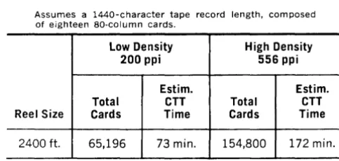
Assumes a 1440-character tape record length, composed of eighteen SO-column cards.
Low Density High Density 200 ppi 556 ppi
Estim. Estim.
Total CTT Total CTT Reel Size Cards Time Cards Time
2400ft. 65,196 73 min. 154,800 172 min.
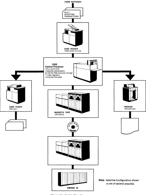
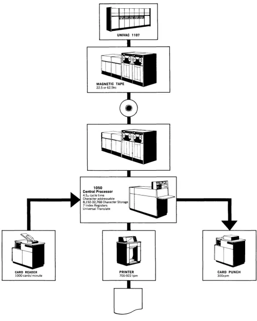
Figure 4-1 illustrates the application of the UNIVAC 1050 System for card-to-tape function only. The concurrent application of this function will be discussed in a subsequent section.
In the example shown, it is possible to perform a programmed input audit on the punched card data for sequence checking, zone punching, numeric field validation, and so on. The punch or printer can be used to signal invalid items that require off-line corrections. Similarly, control totals or listings can be produced. The output tape data can be edited as required.
TAPE TO PRINTER
A large scale system with high internal processing speeds can be limited on some applications by the output speed of its printer. Therefore, while data has been processed, computations and editing com-pleted, the entire large scale system is marking time waiting for the completion of the previous printer operation. In such cases, it is recommended that the output be recorded on magnetic tape. By doing so the large scale system utilizes its fastest output device, which most closely approximates its internal processing speed. The advantages to be derived will be both a decreased large scale systems cost and an increased amount of large scale systems time available for other applications.
In terms of output speeds, the printer can produce printed reports at a rate of 922 lines per minute for alphanumeric data. The printer provides a 128-character print line. Where shorter reports are required, a 64-character print line can be utilized.
UP-2590
CARD PUNCH
300cpm
1050
Central Processor
4.5/,s cycle time
FROM KEYPUNCH
CARD READER
1000 cards/minute
character addressable 8,192-32,768 character storage 7 index registers
Universal translate
IIIIIIIIIIIIIIII~
UNIVAC III
Figure 4-1. Card to Tape Conversions.
PRINTER
700-9221pm
Note: Satellite Configuration shown is one of several possible.
The print spacing is 10 characters per inch hori-zontally and either 6 or 8 lines per inch vertically.
Paper advance is program controlled allowing a wide degree of choice. The instruction repertoire of the UNIVAC 1050 System provides several in-structions that simplify the programming of the appropriate controls. In addition there is a set of manual adjustments on the printer control panel to aid in forms alignment both initially and while the printer is in operation.
Magnetic tapes from large scale systems such as the UNIVAC III, UNIVAC 490, UNIVAC 1107 Systems can be accommodated through the UN 1-SERVO III A Control Unit. Tapes compatible with the IBM 1410, 705, 7070, 7080, 7090 Systems can be accommodated through the III C Control Unit.
The III C Tape Control Unit provides automatic translation of tapes written in BCD mode. Tape length is 2400 feet. The previous approach of using either 132- or 792-character record length is followed. The tape reel capacity is shown in the chart at the bottom of the page.
Figure 4-2 illustrates the tape to printer operation of the UNIVAC 1050 System. Concurrent applica-tions will be discussed later.
Tape speeds are more than sufficient to provide a steady flow of input data to match output require-ments. The high density of magnetic tape plus variable record length format allows a high degree of flexibility in the preparation of data for the High-Speed Printer. The data may be edited either on the large scale system or the UNIVAC 1050 System.
The III A tape reels available are 600, 1800 and
UNISERVO IIIC TAPE CAPACITY
3500 feet in length providing for light, medium 01'
heavy volumes of data as required.
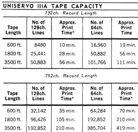
To illustrate the data capacity of magnetic tape reels, two approaches have been chosen. In the first a tape record is composed of either a single 128-character, or two 64-character print lines, plus controls. The total tape record length is 132 char-acters. In the second, the record is composed of six 128-character, or twelve 64-character print lines, plus controls. The total tape record length is 792 characters. The first is the simplest method of as-signing one print line to one tape record. The sec-ond is a more sophisticated approach of assigning a number of print lines to a tape record. The second method increases tape reel capacity and re-duces the amount of manual operator intervention for the replacement of tape reels.
UNISERVO lilA TAPE CAPACITY
132ch. Record Length
No. of Approx. No. of Approx. Tape 128ch. Print 64ch. Print Length Lines Time* Lines Time 600ft. 8480 10min. 16,960 19 min. 1800 ft. 25,441 28min. 50,882 56 min. 3500ft. 50,883 56 min. 101,766 111 min.
792ch. Record Length
No. of Approx. No. of Approx. Tape 128ch. Print 64ch. Print Length Lines Time* Lines Time* 600ft. 32,142 35 min. 64,284 70min. 1800ft. 96,426 105 min. 192,852 210 min. 3500ft. 192,852 210 min. 385,704 419min. *Timing is based on continuous printing, single line spacing
(922 Ipm), rounded to whole minutes.
132ch. Record Length
No. of 128ch. Lines Approx.* Print Time No. of 64ch. Lines Approx.* Print Time
Low Density 20,422 23 min. 40,844 45 min.
High Density 29,149 32 min. 58,298 64min.
792ch. Record Length
No. of 128ch. Lines Approx.* Print Time No. of 64ch. Lines Approx.'" Prmt Time
Low Density 36,684 40min. 73,368 80min.
High Density 79,410 87 min. 158,820 173 min.
UP-2590
CARD READER
1000 cards/ minute
~
UNIVAC 1107
1050 Central Processor
4.51' cycle time Character addressable 8,192-32,768 Character Storage 7 Index Registers
Universal Translate
PRINTER
700-9221pm
-Figure 4-2. Tape to Printer Operation.
CARD PUNCH
300cpm
TAPE TO CARD
The maintenance of punched card files and the creation of punched card "turn around" documents or summary cards are necessary functions that can be performed as a satellite application. By writing this'data on magnetic tape, the large scale system can perform this task in the shortest pos-sible time. The tapes can then be processed by the UNIVAC 1050 System to produce the punched card output required. Because the burden of pro-duction is shifted to the satellite computer which is especially suited for such application, the large scale system is free for other activities.
The equipment characteristics of both the large
scale and the UNIVAC 1050 Systems must be con-sidered in determining the tape record length to be used. Large scale systems are most efficiently utilized when producing long tape records. How-ever, the amount of storage available for tape in-put and the size of the program on the satellite tend to limit the size of a tape record.
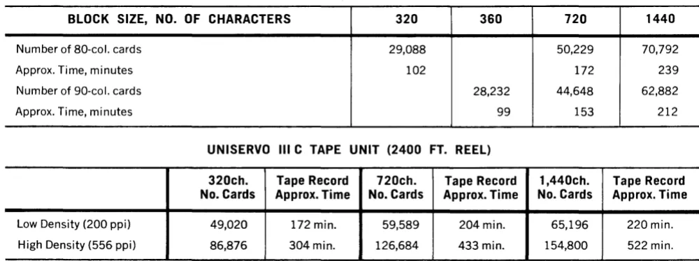
Based on the above considerations, the following illustrates the effect of tape record length in rela-tion to tape reel capacity and processing time per reel.
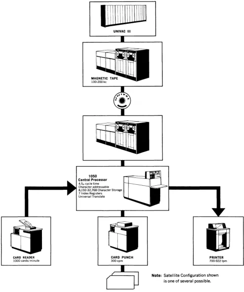
Figure 4-3 illustrates the tape to card application
of the UNIVAC 10pO System. Concurrent
applica-tions will be discussed later.
UNISERVO III A TAPE UNIT (600 FT. REEL)
BLOCK SIZE, NO. OF CHARACTERS 320 360 720 1440
Number of 80-col. cards 29,088 50,229 70,792
Approx. Time, minutes 102 172 239
Number of 90-col. cards 28,232 44,648 62,882
Approx. Time, minutes 99 153 212
UNISERVO III C TAPE UNIT (2400 FT. REEL)
320ch. Tape Record 720ch. Tape Record 1,440ch. Tape Record No. Cards Approx. Time No. Cards Approx. Time No. Cards Approx. Time
UP-2590
CARD READ£R
1000 cards/minute
1Jj1111\lllllllln
UNIVAC III
1050
Central Processor
4.51' cycle time Character addressable 8,192-32,768 Character Storage 7 Index Registers
Universal Translate
CARD PUNCH
300cpm PRINTER 700-9221pm
Note: Satellite Configuration shown is pne of several possible.
Figure 4-3. Tape to Card Conversion.
CONCURRENT PROGRAM OPERATION
The outstanding features of the UNIVAC 1050 System are especially apparent during the run-ning of concurrent programs. Two programs will not only share storage but will also overlap input-output operations. This effective utilization of storage is accomplished through the advanced clesign of the program interrupt concept. Each peripheral unit has a unique area in storage to which a program will proceed as soon as the input-output function has been completed. There-fore, as soon as an input-output unit accomplishes its function, the present program is interrupted temporarily and control is given to the specific unit's unique area. In this manner, input-output operations are overlapped so that optimum speeds may be achieved.
Tape reading or tape writing can proceed con-currently with printing since the printer buffer reduces the storage demands. Of course, the stor-age requirements of the High-Speed Reader and Card Punch Unit must be considered in weighing such factors as block size, storage available for input-output areas, and complexity of the pro-gram. In general, there is a direct relationship between the block size and the attainment of opti-mum card reader or punch speeds. This is illus-trated in the follo'wing comparison which shows the effect of block size on reader speeds and the estimated time to perform card-to-tape and tape-to-printer operations, both individually and con-currently.
CARD-TO-TAPE TAPE-TO-PRINTER TOTAL
SINGLE
NO. OF CARDS PER NO. OF LINES PER RUNS CONCURRENT
CARDS BLOCK TIME* LINES BLOCK TIME* TIME* TIME*
25,000 5 30 25,000 5 28 58 35
25,000 11 28 25,000 11 28 56 31
25,000 17 27 25,000 17 28 55 29
5.
PROGRAMMING THE UNIVAC 1050 SYSTEM
5. PROGRAMMING THE UNIVAC 1050 SYSTEM
Most programming for the UNIVAC 1050 System will be written in the language of the PAL
As-sembly System - an easy to learn, easy to use
source language. The PAL assembler, with its related Input-Output Library and diagnostic serv-ices, is designed for convenience of writing and understanding programs for the UNIVAC 1050 System. Numerous checking facilities and diag-nostic services are furnished to enable the user to work entirely in the language of PAL and its associated services. Any action based on attempts to employ forms of the instructions not described in this reference manual deviates from Univac rec-ommendations and must bethe user's responsibility.
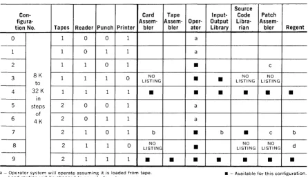
A summary of the total software package, along with the system configurations required to utilize the software is shown in Figure 5-1. A detailed description of the software routines appears later in this section.
PAL ASSEMBLY SYSTEM
A source language statement may generate a single machine language instruction; generate several machine language instructions; or direct the assembler. Statements which generate a single machine instruction are called symbolic machine instructions. All others are called symbolic non-machine instructions.
PAL incorporates a minimum set of assembler direc-ti ves and rules and allows the programmer to refer to fields in storage with a single expression. In addition to the assembly system described in the following sections, there is a card version of PAL. This does not provide I/O specialization as
part of the assembly - a special pass is required.
The card assembler also does not provide input/ output macro instructions, or the assembly ·direc-tives PROC, NAME, or DO.
Operator System
These routines allow the operator to load and start programs which are to operate
indepen-dently or concurrently. These routines assure effective utilization of the various input-output channels for two programs running concurrently. A detailed description of the Operator System will be published separately.
Input-Output Library
The library includes a complete set of input-out-put routines which allows the user to call on
5-2
Source
Con- Card Tape Input- Code Patch
figura- Assem- Assem- Oper- Output Libra-
Assem-tion No. Tapes Reader Punch Printer bIer bIer ator Library rian bIer Regent
0 1 0 0 1 a
1 1 0 1 1 a
2 1 1 0 1
•
c
-8K NO NO NO
3 1 1 1 0
to LISTING
•
•
LISTING LISTING4 32 K 1 1 1 1
•
•
•
• •
•
in
5 steps 2 0 0 1 a
of
6 4K 2 0 1 1 a
7 2 1 0 1 b
•
b•
c bNO NO NO
8 2 1 1 0 LISTING
•
LISTING LISTING d9 2 1 1 1
•
•
• •
•
• •
a - Operator system will operate assuming it is loaded from tape. _ - Available for this configuration. Load routine will be changed to operate from tape.
b - Output can be placed on tape.
c - Patch assembler not prepared to update a tape.
d - Regent can operate - no listing of program or of program errors. Regent is primarily for card-or-tape to printer operations.
Figure 5-1. Standard 1050 Configurations.
Patch Assem bier
This routine allows the user to make modifica-tions to an object program without reassembly. The Patch Assembler accepts corrections in PAL source language and produces an output which supplements and amends the original object code produced by the PAL Assembly System. These same corrections can be used later to update the original source code for a full reassembly.
Report Program Generator (REGENT)
This routine accepts input in the form of specifi-cation cards which describe the input format and the desired report output format, and produces an obj ect program ready to run.
Source Code Librarian
This routine facilitates the maintenance of a file of SOUl'ce code programs. The Source Code Libra-rian allows for changes, insertions and deletions.
A detailed description of the Source Code Li-brarian will be published separately.
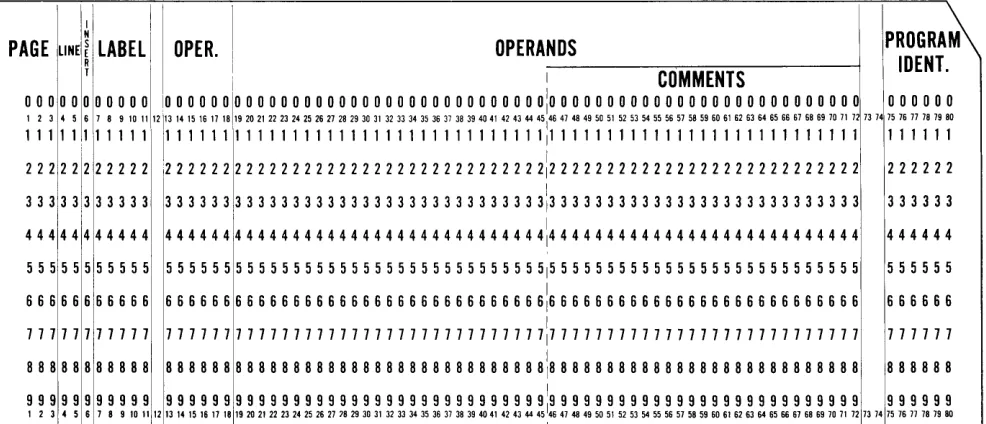
SYMBOLIC CODING FORMAT
Programs are written on the standard coding form shown in Figure 5-2. In the description of this form, which follows, certain terms are used with specific definitions:
• Alphabetic character means a character of the English a.lphabetic set A through Z.
• Numeric character means a character of the Arabic nnmeral set 0 th1'ough 9.
• Alphannm,(,Tic character nwans a character of e1'ther of the al)ove sets (A through Z, 0 through
9).
The symbolic coding fornlat is composed of fixed format fields for program identification, page, line, insert, label, operation, and variable format fields for operands and comments.
It will be noted that numbers are associated with
each subdivision of the coding form. These indi-cate the card columns into which the characters written by the programmer are to be punched. These column numbers hold true for both 80- and 90-column cards. The 80-column source card is shown in Figure 5-3; the 90-column source card, in Figure 5-4.
C
"tI
N UI
10
o
UNIVAC
PROGRAM---SEQUENCE
"
00" c: en (J1'"
""tJ » r (") o a. ::J (JQ"
o ~ PAGE 3I I I I
I I I I I I
I I I I
I I
I I I I I I
I I I I
I I I I
I I
I I I I I I
I I
I I
I I
I I I I
I I
I I
I I
I I LINE
~~ 7 4 5
I I I I I I I I I I I I I I I I I I I I I I I I I I I I
LABEL OPERATION
11 13 18 19
I I I I I I I I I I I I I I I I I I I I I I I I I I I
I I I I I I I I I I I I I I I I I I I I I I I I I I I I I I I I I I I I
I I I I I I I I I
I I I I I I I I I
I I I I I I I I I
I I I I I I I I I
I I I I I I I I I I I I I I I I I I
I I I I I I I I I I I I I I I I I I I I I I I I I I I I I I I , I , , ,
I I I I I I I I I I I I I , I I I I
I I I I I I I I I
I I I I I I I I I I I I I I I I I I I I I I I I I I I
I I I I I I I I I I I I I I I I I I I I I I I I I I I
I I I I I I I I I
I I I I I I I I I
(
UNIVAC@ 1050
PROGRAM·ID PAL ASSEMBLER CODING FORM
PROGRAMMER ______________ _ DATE ______________ __ PAGE _ _ _ OF _ _ _ _ PAGES
I I OPERANDS 4S!46 COMMENTS
i
i Ii
i
•i
ii
·
·
!
i
·
i
i5-4
Program-Id Field
~ ! ! !
HIEi TipiAiY
I I I I I751 I I I 180
The program identification, in effect the name of the program, is composed of one to six alphanu-meric characters. The first character is left justi-fied; that is, character position 75 is always used.
Sequence
PAGE, LINE, AND INSERT FIELDS
The page field entry is three numeric characters and is regarded as part of a five character field
consisting of the page and line fields.
The line field entry consists of two numeric char-acters. Each line entry must be sequentially higher than any preceding line with the same page entry. The insert field entry consists of one numeric character. This field is used when a line of coding is to be inserted on a particular page following a particular line. To insert a line of cod-ing between lines 23 and 24 of page 10, the codcod-ing used could be:
SEQUENCE
PAGE LINE
'1
~
3 <4 5
o
1110 213 7I I I I )
The only restriction on the character used for INS is that, if more than one instruction is to follow a particular page line, each insertion line must have a sequentially higher INS number than any pre-ceding it.
Note: The card punched for an INS line must be physically inserted in its proper place in the pro-gram deck punched from the rest of the PAL cod-ing. A card produced from the previous example would have to be inserted between the cards for lines 23 and 24 of page 10.
Label Field
If a line is to have a label, it is written in the LABEL field. A label is one kind of symbol. A symbol is composed of one to five alphanumeric characters, the first of which is an alphabetic character. The first character of a LABEL field entry must be left justified. Except in the case of area statements, the LABEL is assigned an address equal to the address of the least significant char-acter of the line of information with which it is associated.
Operation Field
The OPERATION field is a six character field and may contain an assembler directive, a mnemonic machine instruction code, or a data generating code. An entry in this field must be left justified.
OPERATION
13 18
81DI21 I I
PIRIOICI I
-Operands Field
The OPERANDS field is composed of a string of expressions separated by commas and is termi-nated by the first blank following a nonblank other than comma. Column 72 of the line also terminates the OPERANDS field. Any expression is termi-nated by a blank or comma; however, it can have any number of preceding blanks. If an expression is terminated by a comma, this indicates that an-other expression follows. The maximum number of expressions on a line and the interpretation of each expression is determined by the contents of the OPERATION field; however, any line may have less than the maximum number of expres-sions. A line can be continued on a second line by writing a minus (-) in the most significant char-acter position of the OPERATION field of that line. Only one continuation line is permitted.
The form of the OPERANDS field for each sym-bolic machine instruction is shown in Figure 5-5.
1'1
N 1PROGRAM
PAGE
LlNEI~
LABEL [ OPER. OPERANDSIOENT. T
i 1 COMMENTS
o 0 0 00000000 10 0 0 0 0 010 0 0 0 0 0 0 0 0 0 0 0 0 0 0 0 0 0 0 0 0 0 0 0 0 0 0:0 0 0 0 0 0 0 0 0 0 0 0 0 0 0 0 0 0 0 0 0 0 0 0 0 0 0 000000
123 4567891011 121131415161718,192021222324252627282930313233343536373839404142434445
1464748495051525354555657585960616263646566676869707172 7374 757677787980
111 111<11111 1111111111111111111111111111111111!111111111111111111111111111 111111
1111112111
2 2 2 ;2 2 2 2 2 2 2 2 2 2 2 2 2 2 2 2 2 2 2 2 2 2 2 2 2 2 2 2 2 2 2 2 2: 2 2 2 2 2 2 2 2 2 2 2 2 2 2 2 2 2 2 2 2 2 2 2 2 2 2 2 222222
3 3 3 33+ 3 3 3 3 3 3 3 3 3 3 3 3 3 3 3 3 3 3 3 3 3 3 3 3 3 3 3 3 3 3 3 3 3 3 3 3 3113 3 3 3 3 3 3 3 3 3 3 3 3 3 3 3 3 3 3 3 3 3 3 3 3 3 3 333333
1 1
444444 444 444144444 4 4 4 4 4 4 4 4 4 4 4 4 4 4 4 4 4 4 4 4 4 4 4 4 4 4 4 4 4 4 4 4 414 4 4 4 4 4 4 4 4 4 4 4 4 4 4 4 4 4 4 4 4 4 4 4 4 4 4
5 5 5 5 5 555555 555555 5 5 5 555 5 5 5 5 5 5 5 5 5 5 5 5 5 5 5 5 5 5 5 5 515 5 5 5 5 5 5 5 5 5 5 5 5 5 5 5 5 5 5 5 5 5 5 5 5 5 5 555555 6 6 6 6 6 666666 666666 6 6 6 6 6 6 6 6 6 6 6 6 6 6 6 6 6 6 6 6 6 6 6 6 6 6 616 6 6 6 6 6 6 6 6 6 6 6 6 6 6 6 6 6 6 6 6 6 6 6 6 6 6 666666
777 77 777777 777777 7 7 7 7 7 7 7 7 7 7 7 7 7 7 7 7 777 7 7 7 7 7 7 7 717 777 7 7 7 777 777 7 7 7 7 7 777 7 7 7 7 7 7 777777
8 8 8 8 8 888888 888888 8 8 8 8 8 8 8 8 8 8 8 8 8 8 8 8 8 8 8 8 8 8 8 8 8 8 8:8 8 8 8 8 8 8 8 8 8 8 8 8 8 8 8 8 8 8 8 8 8 8 8 8 8 8 888888
9 9 9 9 9 999999 999999 9 9 9 9 9 9 9 9 9 9 9 9 9 9 9 9 9 9 9 9 9 9 9 9 9 9 919 9 9 9 9 9 9 9 9 9 9 9 9 9 9 9 9 9 9 9 9 9 9 9 9 9 9 999999
123 4 5 67891011 12131415161718 19202122232425262778293031 323334353637383940 41 424344 451
46 47 48 49 50 51 5253545556575859606162636465666768697071 72 7374 757677787980 1
Figure 5-3. PAL BO-Column Source Card.
1
LABEl I
N I \
PAGE LINE s
OPERATION OPERANDS :
1\
E R 1-2
-'z
-12- -12-'2- !::
-:~-~:
-::--:l
12 12-'2-12-12-12- 12 12 12 12 12 12 12 '2 '2 12 '2 '2-- - - _ _ _ _ _ _ _ _ _ _ _ _ _ -'2-' i -'2-12 -12- -12-'2--'2 -12 -1-2-12 -12-l
z
-12--12: I'z
14 14 34 34 34 34 34 34 34 34 34 34 34 34 34 34 34 34 14 14 14 34 34 14 14 14 14 14 14 34 34 34 34 34 14 34 34 34 : 34 I56 56 56 56 56 56 56 56 56 56 56 56 56 56 56 56 56 56 56 56 56 56 56 56 56 56 56 56 16 II> II> 16 56 56 56 56 56 56 56 56 56 56 56: 56 I 78 78 78 78 78 78 78 78 78 78 78 78 78 78 78 78 78 78 78 78 78 78 I
78 /8 7H 78 78 7H 7H 7 H 7 H 78 78 78 78 78 78 78 78 78 78 78 78 : 78
1 2 3 4 5 6 7 8 9 10 11 12 13 14 15 16 17 18 19 20 21 22 23 2. 25 26 27 28 29 30 31 32 33 3. 35 36 37 38 39 40 41 42 43 44 I 45 I
OPERANDS / COMMENTS PROGRAM
IOENTIFICA TION - - - ------
-12 '2 -12 '2 '2 '2 12 12 12 12 12 12 12 12 12 12 12 12 12 12 '2 '2 12 12 12 12 12 12-12- -'2 -12-12-12
---14 34 34 ---14 '4 '4 ---14 34 34 '4 34 34 34 34 34 34 34 34 34 34 34 34 34 34 34 34 34 34 34 34 34 '4 14
\6 56 56 56 56 56 56 56 56 56 56 56 56 56 56 56 56 56 56 56 56 56 56 56 56 56 56 Is
6 56 56 56 56 56 78 7H 78 78 78 78 78 78 78 78 78 78 78 78 78 78 78 78 78 78 78 78 78 78 78 78 78
78 78 78 78 78 78
9 9 9 9 9 9 9 9 9 9 9 9 9 9 9 9 9 9 9 9 9 9 9 9 9 9 9 9 9 9 9 9 9
46 47 48 49 50 51 52 53 5. 55 56 57 58 59 60 61 62 63 64 65 66 67 68 69 70 71 72 73 7. 75 76 77 78 79 80 81 82 8' 8' 85 86 87 88 89 90
5-6
Not all expressions need to be written in some cases. For example, a symbol written as the M expression on an instruction line may also define the length of the field addressed. In this case, the L portion of the instruction line may be omitted.
Some possible forms for the OPERANDS field are:
OPERATION
OPERANDS
13 18 19
I I I I I M, L, X
)
1 1 1 1 1 M" X 1 1 1 1 1 M,L
I 1 I I I M J
I I J I I , L
1 I I I I M, S, X
\
I I 1 I I M, S
\
1 1 1 1 I M, I, X
J
1 1 I 1 1 M, I
I I I I I M,N,X I
M,N
,
I I I I I
I I I I I M,C
-I -I -I -I -I M,T
1 1 1 1 1 F,O,U,X
)
I I I I I F, " X
-
\i""'"
-
-Note that if the last expression which might ap-pear on a line is omitted, the comma which would have preceded it is omitted.
Additional Rules
The remaining rules for the use of the PAL coding form are:
1. COMMENTS is shown for character positions 46 through 72. This is an artificial division rec-ommended for standard positioning of comments on the printed listing. COMMENTS consists of notes or remarks concerning the program to be processed by the PAL Assembly System. These notes do not affect the processing of a line and are not reflected in object coding. COMMENTS can appear on any line following the last expres-sion on the line and separated from it by a blank. (The last expression on a line is termi-nated by a blank. Every line except a COM-MENTS line must have at least one expression.)
2. COMMENTS in addition to those made on nor-mal lines of coding can be introduced at any point in the symbolic coding by use of a COM-MENTS line. The COMCOM-MENTS line consists of a period in the leftmost character position of the label field followed by a blank followed by the comments. A COMMENTS line produces no output coding, but does produce a printed line on the symbolic listing.
3. If an alphabetic character appears in the left-most position of the LABEL field, the field is as-sumed to contain a label of up to five characters.
4. If there is no period or alphabetic character in the leftmost position of the LABEL field, the field is assumed to be blank.
5. Character position 12 is normally left blank.
SYMBOLIC INSTRUCTIONS
In order to use symbolic instructions correctly and efficiently, the programmer must have a basic understanding of how instructions and data are
~tored and addressed, even though he will not be required to specify these details in PAL instruc-tions. Bit positions referred to in the following discussion are numbered from right to left; the least significant bit is number O.
REPRESENTATION OF INFORMATION
IN CORE STORAGE
Data which is to be processed by the UNIVAC 1050 System is read from an external medium such as punched cards or magnetic tape, and placed in coded form in the core storage of the Processor. The data to be stored can consist of alphanumeric or special characters.
Numbers are represented in storage by two differ-ent methods. Certain values, such as an address or index register designation, are stored in a true binary format. Numerical data is usually stored in a character format, as are alphabetic and spe-cial characters. Each character in its coded form occupies six bit positions. A seventh bit position exists for a check or parity bit. Every time a character containing an even number of one bits is read into the system, a check (parity) bit is produced automatically and stored with the char-acter. No parity bit is produced for a character containing an odd number of one bits. Thus, a character will always consist of an odd number of one bits stored in seven bit positions.
Since the user is never directly concerned with the parity bit (it is not accessible to the pro-grammer), it will not be discussed further. When reference is made to a 6-bit character, it will be understood that.a parity bit may also be present. Table 5-1 gives the complete character set, show-ing the equivalent 6-bit binary codshow-ing for each of the external media, together with the collating
( ordering) sequence.
The 6-bit character format is further divided into two portions; the zone portion (bits 5-4) and the numeric portion (bits 3-0). All positive nu-meric data stored in the character format has zero zone bits. A field is negative when its least significant character has a I-bit in position 5. Thus,
+
4 is represented as- 4 is represented as
Data Fields
000111 100111
and
The standard unit of storage is a single 6-bit character which occupies one position of storage. Each field of data, whether a I-character code or a 30-character descriptive name, occupies ex-actly the number of storage positions it requires. This organization permits the greatest economy in the assignment of storage to fit data fields of different lengths. In addition to space economy, the execution time of an instruction is directly related to the length of its associated OPERANDS field.
Representations of Instructions in Core Storage
Instructions, as well as data, occupy core storage. Each instruction occupies five consecutive cha"rac-ter positions, or 30 bits, and successive instruc-tions are placed one after the other, starting in any arbitrarily selected character position. The instruction control counter (CC) keeps track of the address of the most significant character of each instruction, and as each instruction is com-pleted, the counter is incremented by 5. The con-trol counter will step through storage in steps of 5 as the instructions are executed until some ac-tion occurs which overrides this automatic se-quencing and sets the control counter to some other address.
Every instruction is divided into a number of fields. The general format is as follows (see I/O for exceptions. )
OP CODE (Bits 29-25) indicates the form of the operation to be performed.
X (Bits 24-22) indicates the index re-gister to be used, if any, for address modi fica tion.
(Bit 21 disregarded.)
M (Bits 20-6) represents the address of
the least significant digit of the field addressed, except for the block trans-fer, zero suppress and sequence control instructions; also multiply, divide and I/O instruction, which do not address a field.
C (Bits 5-0) have a variety of uses
de-pending upon the operation to be
per-formed; details are given with ~ach
instruction description.
ADDRESSING
Core Storage
Core storage is organized into modules, each capa-ble of storing 4096 characters. A minimum of two
(8192 characters) modules and a maximum of eight (32,768 characters) modules are permissible. Regardless of the size of storage the low order position always has an address of 0, the next posi-tion 1, and so forth. Memory can be considered as a contiguous sequence of position. The last (high order) position has an address one less than the total number of positions. Thus, in a system with 16,384 positions of storage, the last position has an address of 16,383.
The minimum number of binary bits required to specify 32,768 positions is 15; hence the 15-bit address in the instruction format. For ease in presentation, octal numbe:r:ing is used to represent machine address; Appendix A presents a Deci-mal to octal conversion table. If the storage con-tains fewer than 32,768 positions, an instruction which addresses an area outside the actual limits of core storage will result in
• A parity error, if