Decentralized adaptive force/position control of reconfigurable
manipulator based on soft sensors
Yanli Du1 and Quanmin Zhu2
Abstract
T w o s o f t s e n s o r c o n t r o l m e t h o d s a r e p r o p o s e d t o d e a l w i t h f o r c e / p o s i t i o n c o n t r o l o f r e c o n f i g u r a b l e m a n i p u l a t o r s w i t h o u t u s i n g w r i s t f o r c e s e n s o r s . F i r s t l y , m o d e l i n g u n c e r t a i n t i e s a n d c o u p l i n g i n t e r c o n n e c t i o n t e r m s b e t w e e n t h e subsystems are approximated by using adaptive RBF neural network, and the soft sensor model of the contact force is
established by means of adaptive RBF neural network to design hybrid force/position controller. Then, a decentralized impedance inner/force outer loop controller is designed. The reference trajectory of impedance inner controller is provided by force outer loop controller based on the fuzzy prediction, and the soft sensor model of the contact force is established by the fuzzy system. The proposed soft sensor model does not request the exact mathematical relationship between the
end contact force and auxiliary variables, and provides a feasible method to replace the wrist force sensors which are expensive and easily noised by the external factors.Compared with the observer method,the proposed methods provide
better position and force tracking precision.
Keywords
Reconfigurable manipulator,soft sensor,decentralized hybrid force/position control,impedance inner control,adaptive RBF neural network,fuzzy approximation *
1 Introduction
Re c o n f i g u r a b l e m a n i p u l a t o r s c a n f o r m t h e v a r i o u s
c o n f i g u r at i o ns o f d i f f e r e n t d e g r e e s o f f r e e d o m (DOF) to carry out tasks and are widely applied in
t h e fi e l d o f d a n g e r o u s w o r k e n v i r o n m e n t , s p a c e e x p l o r a t i o n , a n d m i l i t a r y , i n d u s t r i a l , m e d i c a l , e n t e r t a i n m e n t e t c. Th e r e a r e m a n y
tasks like polishing, grabbing and operation
t h ra et q u i r e i n t e r a c t i o n b e t w e e n
re c o nm f a i ng iu pr tua hlb eal te o r a n d
e n v i r o n m e n t .T h i s f a c t r e q u i r e s t h a t t h e
p o s i t i o n a n d t h e c o n t a c t f o r c e w i t h t h e e n v i r o n m e n t f o rre c o n f i g u r a b l e m a n i p u l a t o r
should be controlled at the same time. So, m a nr ye s rse a hr acd vho leeno oetf s researches on the force and position control of the manipulator in recent years [1-10].
T h e f o r c e c o n t r o l m e t h o d s o f t h e m a n i p u l a t o r i n c l u d e f o r c e/p o s i t i o n c o n t r o l
[ 1 - 4 ] a n d i m p e d a n c e c o n t r o l [ 5 - 1 0 ] , b u t
these methods require a wrist force sensor to be installed at the manipulator end. In the applications of industrial manipulators, high accurate and reliable force sensors are very expensive, and the use of force sensors will increase the complexity of the manipulator
i n e l e c t r i c a l, m e c h a n i c a l a n d s o f t w a r e p a r t s. T h e r e a r e v a r i o u s u n c e r t a i n t i e s a n d environmental factors in the industrial field,
w h i c h m a y h a v e i n fl u e n c e t o t h e p r e c i s i o n
o f t h e s e n s o r a n d o p e r a t i o n a l r e l i a b i l i t y . In recent years, to improve the reliability of
t h e m a n i p u l a t o r c o n t r o l s y s t e m , e x t e r n a l f o r c e e s t i m a t i o n m e t h o d o f r e c o n f i g u r a b l e
manipulator is proposed. Colomé [11]proposes a
rob us t ob se rve r t o e st imat e co nta ct forc e s
b e t w e e n t h e m a n i p u l a t o r a n d t h e
environment. The force sensor is not used in
t h i s m e t h o d . I n o r d e r t o e s t i m a t e t h e position and force of the manipulator during
*1 College of Electrical Information Engineering, Beihua University, Jilin, China
2Department of Engineering Design and Mathematics,University of the West of England,Bristol BS161QY,UK Corresponding author: Quanmin Zhu ,Department of Engineering Design and Mathematics, University of the West of England, Bristol, UK.
F S W p r o c e s s e s , Q i n [ 1 2 ] p r o p o s e s a n o n
-l i n e a r o b s e r v e r t o e s t i m a t e n o t o n -l y t h e state (position and velocity) of links, but also
t h e e x t e r n a l f o r c e s e x e r t e d b y t h e r o b o t
d u r i n g F r i c t i o n S t i r W e l d i n g ( F S W )
p r o c e s s e s . I n o r d e r t o e n s u r e a b e t t e r tracking performance, the data such as real
p o s i t i o n s , v e l o c i t i e s o f l i n k s a n d e x t e r n a l f o r c e s a r e r e q u i r e d . W a n g [ 1 3 ] d e s i g n s a n
o b s e r v e r t o a p p r o x i m a t e f o r c e,an d in
o r d e r t o o v e r c o m e t h e u n c e r t a i n t y o f t h e environment, the adaptive law of stiffness is
d e r i v e d .C h a n [ 1 4 ] p r o p o s e d a f o r c e e s t i m a t i o n m e t h o d b a s e d o n t h e a c t i v e observer in the presence of the noise for the
r o b o t . I t c a n n o t o n l y e s t i m a t e c o n t a c t f o r c e , b u t a l s o o b s e r v e t h e s t a t e o f t h e
s y s t e m .D u [ 1 5 ] p r o p o s e s a d e c e n t r a l i z e d
a d a p t i v e f o r c e c o n t r o l m e t h o d b a s e d o n
n o n l i n e a r j o i n t t o r q u e o b s e r v e r f o r
r e c o n fi g u r a b l e m a n i p u l a t o r . T h e n o n l i n e a r observer is designed to observe the torque
o f e a c h j o i n t , a n d fi n a l l yg e t t h e c o n t a c t force by Jacobian matrix transformation.
T h e a b o v e m e t h o d s a r e t o e s t i m a t e t h e
c o n t a c t f o r c e b y t h e o b s e r v e r , w h i c h i s d i ffi c u l t t o p r o v e t h e c o n v e r g e n c e o f t h e
o b s e r v a t i o n e r r o r a n d i s e a s i l y a ff e c t e d b y
t h e o b s e r v e d n o i s e . S o , i n r e c e n t y e a r s , many scholars have invested in the research
o f f o r c e c o n t r o l m e t h o d s b a s e d o n s o f t s e n s o r t e c h n o l o g y . R e n [ 1 6 ] a n d C h o [ 1 7 ]
p r e s e n t a s o f t s e n s o r m e t h o d t o s o l v e t h e
p r o b l e m t h a t s t r e s s s i g n a l i s d i ffi c u l t t o obtain in the health monitoring of multibody
manipulator.In the method, stress signal is considered as dominant variable and angle si gn al is re ga rd ed a s au xilia ry v aria ble . By e s t a b l i s h i n g t h e m a t h e m a t i c a l r e l a t i o n s h i p
b e t w e e n t h e m , a s o f t s e n s o r m o d e l i s p r o p o s e d. H a m m o n d [ 1 8 ] p r o p o s e s a s o f t
s e n s o r m e t h o d f o r t h e s u b m i l l i m e t e r contact localization and force measurement
i n m i c r o m a n i p u l a t i o n .T a c t i l e s e n s i n g experiments verify the eff ectiveness of the
m e t h o d .Y a n g [ 1 9 ] h a s d e s i g n e d a n o v e l
pneumatic soft sensor(PSS). According to the
i n n e r p r e s s u r e o f s e n s i n g b o d y , P S S c a n m e a s u r e contact force and curvature by building relation models
o f c o n t a c t f o r c e a n d c u r v a t u r e , a n d i t s m e a s u r e m e n t accuracy is tested by a large of experiments.
T h e a b o v e f o r c e e s t i m a t i o n m e t h o d s b a s e d o n s o f t s e n s o r n e e d t o k n o w t h e
mathematical relationship between contact
f o r c e a n d a u x i l i a r y v a r i a b l e s . F o r
r e c o n fi g u r a b l e m a n i p u l a t o r s y s t e m , i t i s d i ffi c u l t t o d e t e r m i n e t h e m a t h e m a t i c a l relationship between end contact force and
o t h e r a u x i l i a r y v a r i a b l e s . To s o l v e t h e problem and avoid the difficulty in observer design
and convergence analysis, this study presents two
k i n d s o f d e c e n t r a l i z e d a d a p ti v e f o r c e control methods based on soft sensor. One
is th e hy bri d forc e/ po si tion c on trol me tho d
b a s e d o n a d a p t i v e R B F n e u r a l n e t w o r k e s t i m a t i o n . T h e c o n t a c t f o r c e i s e s t i m a t e d
b y R B F n e u r a l n e t w o r k , a n d t h e a d a p t i v e
l a w s o f i t s c e n t e r a n d w i d t h a r e d e d u c e d. T h e o t h e r i s t h e i m p e d a n c e i n n e r / f o r c e
o u t e r l o o p c o n t r o l m e t h o d b a s e d o n t h e F u z z y pr e di ct i o n r ef e r en c e t r aj e ct or y . T he en d co nt a c t f or c e i s a p p r o x i m a te d b y t h e f u z z y s y s t e m s. T h e p r o p o s e d
t w o m e t h o d s d e r i v e a d a p t i v e l a w s o f a l l p a r a m e t e r s , a n d a r e c o m p a r e d w i t h t h e f o r c e e s t i m a t i o n m e t h o d based on the observer.
T h i s a r t i c l e i s o r g a n i z e d a s f o l l o w s . P r o b l e m f o r m u l a t i o n , t h e n e c e s s i t y a n d i m p o r t a n c e f o r s t u d y o f
p o s i t i o n a n d f o r c e c o n t r o l b a s e d o n s o f t s e n s o r i s d e s c r i b e d i n s e c t i o n“I n t r o d u c t i o n”. I n s e c t i o n
“R e c o n f i g u r a b l e m a n i p u l a t o r d y n a m i c
m o d e l”, th e d y n a m i c m o d e l o f r e c o n f i g u r a b l e manipulator and the subsystem dynamic model at each
direction are given. In section “The decentralized force c o n t r o l l e r d e s i g n b a s e d o n s o f t s e n s o r”,de s i g n a n d simulation of two force/position controllers based on s o f t s e n so r a r e p r o p o s e d . T h e l a s t s e c t i o n i s t h e conclusion.
2
R
e
c
o
n
fi
g
u
r
a
b
l
e
m
a
n
i
p
u
l
a
t
o
r
dynamic model
When reconfigurable manipulator is in contact with the
disturbance in the joint space is
(1) w h e r e d e n o t e s t h e j o i n t p o s i t i o n; , a r e
t h e s p e e d a n d a c c e l e r a t i o n o f t h e j o i n t ,
r e s ;p e c ti ist vh ee l yi n e r t i a m a t r i x ;
d o n a t e s t h e C e n t r i p e t a l a n d C o r i o l i s t o r q u e s ; i s t h e g r a v i t a t i o n a l t o r q u e
vector; is the control torque; is
t h e to r q u e v e c t o r e x e r t e d b y t h e m a n i p u l a t o r o n t h e e n v i r o n m e n t; i s t h e ex t e r n a l disturbance.
Consider the following equations[20]
w h e r e i s t h e J a c o b i a n m a t r i x ; F a n d X a r e t h e
c o n t a c t f o r c e a n d p o s i t i o n o f t h e t a s k s p a c e , respectively.
W i t h t h e w o r k s p a c e p o s i t i o n X a s t h e v a r i a b l e , the equation (1) is written as
(2) where
T h e m o d e l o f r e c o n f i g u r a b l e m a n i p u l a t o r i s d e c o m p o se d a t e a c h d i r e c t i o n , a n d t h e d y n a m i c
model of the subsystem j is as follows
(3)
wh e r e i s t h e jt h e l e m e n t o f t h e v e c t o r X a n d
s coupled interconnection between the subsystems.
In the premise of without wrist force sensor, the next
t a s k i s t o d e s i g n t h e c o n t r o l l e r b a s e d o n s o f t sensor for the subsystem equation (3) so as to realize
t h e p o s i t i o n a n d f o r c e c o n t r o l o f r e c o n f i g u r a b l e manipulator in the constrained space.
Figure1. Control block diagram of decentralized hybrid force/position controller
3
T
h
e
d
e
c
e
n
t
r
a
l
i
z
e
d
f
o
r
c
e
controller design based on soft
sensor
c o n t r o l l e r b a s e d o n a d a p t i v e R B F N N s o f t sensor model
3.1.1 Controller design
T h e a d v a n t a g e o f t h e hy b r i d f o r c e/p o s i t i o n c o n t r o l l e r i s a b l e t o d i r e c t l y c o n t r o l c o n t a c t f o r c e . I n t h i s p a r t, P I c o n t r o l a l g o r i t h m b a s e d o n t h e f o r c e e r r o r i s a d o p t e d t o c o n t r o l f o r c e a n d P I D c o n t r o l a l g o r i t h m b a s e d o n t h e p o s i t i o n e r r o r i s u s e d i n t h e p o s i t i o n co nt r ol . In t he a bs e nc e o f w r i s t f o r c e s e ns o r , t h e so f t sensor model of the contact force is established based o n a d a p t i v e R B F N N , a n d s u bs y s t e m u n c e r t a i n t y a n d c o u p l i n g i n t e r c o n n e ct i o n a r e a l s o e s t i m a te d b y u s i n g R B F N N . T h e c o n t r o l b l o c k d i a g r a m o f d e c e n t r a l i z e d hybrid force/position controller is shown in Figure1.
T h e f o r c e e r r o r a n d p o s i t i o n e r r o r o f t h e subsystems are defined as follows:
w h e r e i s t h e e s t i m a t e v a l u e o f , a n d
a r e r e s p e c t i v e l y t h e d e s i r e d p o s i t i o n a n d contact force.
Letting
We have
So
(4)
B r i n g i ng a n d i n t o
equation(3),then equation (3) will be
The above equation is written as
here
We i n t r o d u c e a d e c e n t r a l i z e d c o n t r o l l a w t h a t i s described by
(5-a)
(5-b) (5-c) where is the approximation error compensation;
is the joint torque compensation; and
a r e t h e e r r o r u p p e r b o u n ds o f t h e c o n t a c t f o r c e a n d , r e s p e c t i v e l y ; a n d a r e t h e p o s i t i v e c o n s t a n t s ;i s t h e o u t p u t
mapping of the joint torque sensor;
and are respectively the estimate values o f a n d t h a t c a n b e e x p r e s s e d by using adaptive RBFNN
w h e ,r e a r te h e w e si ;g h t v e c t o r a n d a r e t h e ra d i a l
b a s i s f u n c t i o ns ( I n t e r n a l s t r u c t u r e o f R B FN N f o r estimating contact force refers to Appendix I).
T h e f o l l o w i n g a d a p t i v e l a w s o f t h e p a r a m e t e r s are obtained
(6-b)
(6-c)
(6-d)
(6-e)
(6-f)
where , and , are centers and widths of the radial basis function
and , respectively; , , , , , are the positive constants.
Property 1. For the scalar function and
, there is the following equation [21]:
Assumption 1. Approximation errors of RBFNN are assumed to be bounded by , , where and are the approximation errors of and , respectively.
T h e o r e m 1 .F o r t h e s u b s y s t e m d y n a m i c m o d e l described byequation (3), if the decentralized control
l a w s s u c h a s equ a t i o n( 5 ) a n d a d a p t i v e l a w s o f t h e p a r a m e t e r s s u c h a s equ a t i o n( 6 ) a r e a p p l i e d , t h e p o s i t i o n e r r o r a n d f o r c e e r r o r o f r e c o n f i g u r a b l e m a n i p u l a t o r s y s t e m w i l l a s y m p t o t i c a l l yc o n v e r g e t o
zero in the constrained space.
Proof.The Lyapunov function is defined by
where
where ,and the other error variables are like this.
Th e t i m e d e r i v a t i v e o f L y a p u n o v f u n c t i o n
is
Using property 1 and control law equation (5), it is easy to show that
For an arbitrary function , its estimate value is ,where
(7)
where .
A c c o r d i n g t o T a y l o r s e r i e s e x p a n s i o n , w e can obtain
(8)
By analogy with equation (7) and equation (8), we get
Since and adaptive
l a ws o f t h e p a r a m e t e r s i n t h e equ a t i o n (6 ) a r e introduced into above equation, we get
A c c o r d i n g t o t h eequ a t i o n ( 5 - c ), t h e a b o v e inequality can be written
A p p l y i n g equ a t i o n ( 5 - b ) , i t i s e a s y t o o b t a i n
, namely .
Because
,
it i s o b v i o u s t h a t . B y equ a t i o n ( 4 ) c a n b e
known .According to Babalat lemma [22],
,and this means that the theorem is
proved.
3.1.2 Simulation results
T h e d e s i g n e d c o n t r o l l e r i s a p p l i e d t o 2- D O F p l a n a r
r e c o n f i g u r a b l e m a n i p u l a t o r i n t h e F i g u r e 2(a).
(a) 2-DOF planar manipulator (b) 3-DOF reconfigurable manipulator
Figure 2. Reconfigurable manipulator configurations
The desired position trajectory is defined as in the Y direction, and the desired force is in the X direction.
T o s h o w t h e e f f i c i e n c y o f t h e p r o p o s e d m e t h o d i n i m p r o v i n g t h e t r a c k i n g a c c u r a c y , t h e o b s e r v e r i n r e f e r e n c e [1 5 ] i s a l s o e m p l o y e d i n t h e s i m u l a t i o n f o r comparison. The simulation results under the proposed
s o f t s e n s o r a n d t h e o b s e r v e r a r e d e p i c t e d i n F i g u r e s 3.
(b) X direction force tracking
Figure 3. Force and position tracking of 2-DOF planar manipulator
T h e 3- D O F r e c o n f i g u r a b l e m a n i p u l a t o r i s s h o w n
i n F i g u r e 2 ( b ) . T h e c o n t a c t f o r c e i s c o n t r o l l e d i n Z direction of the constrained surface, and the position
trajectories are controlled in Y and X directions. Given
t h e d e s i r e d f o r c e , a n d d e s i r e d t r a j e c t o ri e s a r e s e t t o b e ,
. T h e s i m u l a t i o n r e s u l t s a r e s h o w n i n Figure 4.
(a) X-Y plane position tracking
(b) Z direction force tracking
Figure 4. Force and position tracking of 3-DOF manipulator
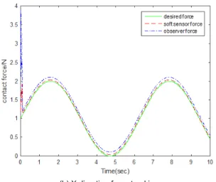
It is observed from Figures 3 and 4 that in the initial stage of the observer, the observer lacks the knowledge of the subsystem dynamics model, so its tracking error is relatively large during the first 0.5 s.In the following tracking process, the observer is easily affected by the
J a c o b i m a t r i x t r a n s f o r m a t i o n a n d t h e p a r a m e t e r s of the proposed soft sensor method are adjusted in real
t i m e a c c o r d i n g t o t h e f o r c e e r r o r a n d t h e p o s i t i o n error,so the simulation accuracy of the proposed soft
s e n so r m e t h o d i s b e t t e r t h a n t h e o b s e r v e r
method.
It is worth noting that this method can cause certain
i m p a c t f o r c e w h e n t h e m a n i p u l a t o r m o v e s f r o m f r e e s p a c e t o c o ns t r a i ne d s p a c e , s o i t i s o n l y s u i t a b l e f o r
position and force control in constrained space.
3.2 The design of impedance inner/ force outer loop
c o n t r o l l e r b a s e d o n a d a p t i v e f u z z y s o f t s e n s o r model
T h e im p e d a n c e c o n t r o l m e t h o d c a n r e a l i z e i n d i r e c tl y
f o r c e c o n t r o l b y a d j u s t i n g t h e r e f e r e n c e p o s i t i o n . The soft sensor model of the contact force is established
b a s e d o n a d a p t i v e f u z z y s y s t e m i n th e p r o p o s e d method, and corrected value of the reference trajectory
f o r t h e i m p e d a n c e i n n e r c o n t r o l l e r i s p r o v i d e d b y output of the force outer loop controller based on the fuzzy prediction.
3 . 2 . 1 T h e r e f e r e n c e t r a j e c t o r y a l g o r i t h m b a s e d o n the fuzzy prediction
T h e a l g o r i t h m c o n s i s t s o f t h e f o l l o w i n g parts:
1 ) T h e r e f e r e n c e t r a j e c t o r y t h a t m a k e s t h e c u r r e n t
o u t p u t v a l u e g r a d u a l l y t r a n s i t t o t h e s e t t i n g value. The equation is written as
w h e r e i s t h e s o f t n e s s c o e f f i c i e n t , i s t h e sampling time, is the predictive step.
2) The prediction model is chosen as
p o s i t i o n s t i f f n e s s m a t r i c e s, r e s p e c t i v e l y . Th ey a r e replaced by the and in the subsystem; is the pos it i on of the mani pulat or; i s the r efer ence
t r a j e c t o r y o f t h e i m p e d a n c e i n n e r c o n t r o l l e r . The selected model is equivalent to
3) The prediction output (equivalent to the feedback correction) is
where is the correction coefficient.
3.2.2 Controller design and prove
T h e bl o c k d i a g r a m o f i m p e d a n c e c o n t r o l s y s t e m i s shown in Figure 5.
The force error and position error are defined as
They are introduced into the first order filter
w h e r e , a n d a r e t h e p o s i t i v e c o n s t a n t s , and are the filter outputs.
i s d e f i n e d b y ,na m e l y . T h e t i m e d e r i v a t i v e o f i s given by
Fig.5 Block di Figure 5. Block diagram of impedance control system
The above equation is rewritten as
(9)
B y c h o o s i n g
, a n d , e q u a t i o n ( 9 ) i s i d e n t i c a l t o t h e target impedance as follows equation (10).
(10)
where is the desired inertia.
Differentiating with respect to time, we have
(11)
The control law is obtained as:
(12-b)
(12-c) where
, , , , , are error upper bounds of of , , ,
,
and , respectively; ,
, , , ,
are the estimates of , , , ,
and , respectively; is the output mapping of the joint torque sensor; is the compensation of the estimation error ; is the compensation of the joint torque measured value; is the positive constant.
The fuzzy system representations are described by
w h e r e , , , , a n d a r e th e
a d j u s t a bs, l er e ; ps ap re ac mt ie vt ee lr y v e c t o r
, , , ,
a n d a r e t h e fu z z y
b a s i s f u n c t i o n v e c t o rs , r e s p e c t i v e l y( M e m b e r s h i p f un ct i on of f uz zy s ys t e m f or es t i m a t i n g c on t a ct f or c e refers to Appendix II).
The adaptive laws of the parameters are (13-a)
(13-b) (13-c)
(13-d)
(13-e) (13-f)
where , , , , , are the positive constants.
Assumption 2. Approximation errors of the fuzzy
s y s t e m a r e a s s u m e d t o b e b o u n d e d b y ,
, , , ,
, w h e r e , , , , a n d
a r e a p p r o x i m a t i o n e r r o r s o f , ,
, , a n d
, respectively.
T h e o r e m 2 .F o r t h e s u b s y s t e m d y n a m i c m o d e l described by equation (3), reconfigurable manipulator
s y s t e m a c h i e v e s t h e t a r g e t i m p e d a n c e e q u a t i o n ( 1 0 ) with the decentralized control law equation (12) and the adaptive laws of the parameters equation (13).
where
Differentiating with respect to time, then
Using equation (12-a), we get
Applyingequation (13) and assumption 2,
Substituting equation (12-b) into inequation, it is easy t o o b t a i n , .
Because
, so
. By equation (11) may be known
.A c c o r d i n g [2 ]t 2,o B a b a l a t l e m m a
,so theorem is proved.
3.2.3 Simulation results
T h e d e s i g n e d i m p e d a n c e c o n t r o l l e r i s a p p l i e d t o
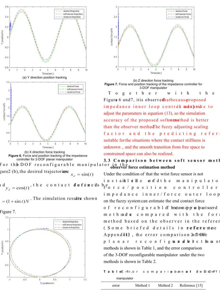
2- D O F r e c o n f i g u r a b l e m a n i p u l a t o r i n t h e F i g u r e 2 ( a ). T h e de s i r e d f o r c e i s ,t h e
d e s i r e d t r a j e c t o r y i s . T h e s i m u l a t i o n results under the proposed soft sensor and the observer
(a) Y direction position tracking
(b) X direction force tracking
Figure 6. Force and position tracking of the impedance controller for 2-DOF planar manipulator
F o r t h e 3- D O F r e c o n f i g u r a b l e m a n i p u l a t o r i n t h e Figure 2 (b), the desired trajectories are
a n d , t h e c o n t a c t f o r c e i s d e f i n e d b y . The simulation results are shown in Figure 7.
(a) X-Y plane position tracking
(b) Z direction force tracking
Figure 7. Force and position tracking of the impedance controller for 3-DOF manipulator
T o g e t h e r w i t h t h e t r a c k i n g r e s p o n s e s o f Figures 6 and 7, it is observed that because proposed
i m p e d a n c e i n n e r l o o p c o n t r o l m e t h o d i s a d a p t i v e t o adjust the parameters in equation (13), so the simulation accuracy of the proposed soft sensor method is better than the observer method.The fuzzy adjusting scaling
f a c t o r a n d t h e p r e d i c t i n g r e f e r e n c e t r a j e c t o r y a r e suitable for the situations where the contact stiffness is
unknown,and the smooth transition from free space to constrained space can also be realized.
3. 3 C o m p a r i s o n b e t w e e n s o f t s e n s o r m e t h o d a n d observer force estimation method
Under the condition of that the wrist force sensor is not
i n s t a l l e d in t h e e n d o f t h e m a n i p u l a t o r , h y b r i d
f o r c e / p o s i t i o n c o n t r o l l e r b a s e d o n R B F N N a n d i m p e d a n c e i n n e r / f o r c e o u t e r l o o p c o n t r o l l e r b a s e d
on the fuzzy system can estimate the end contact force o f r e c o n f i g u r a b l e m a n i p u l a t o r. T h e t w o p r o p o s e d
m e t h o d s a r e c o m p a r e d w i t h t h e f o r c e e s t i m a t i o n m e t h o d b a s e d o n t h e o b s e r v e r i n t h e r e f e r e n c e [ 1 5 ]
( S o m e b r i e f e d d e t a i l s i n r e f e r e n c e [ 1 5 ] r e f e r s t o A p p e n d i x I I I),th e e r r o r c o m p a r i s o n o f t h e 2- D O F
p l a n a r r e c o n f i g u r a b l e m a n i p u l a t o r u n d e r t h e t w o methods is shown in Table 1, and the error comparison
of the 3-DOF reconfigurable manipulator under the two methods is shown in Table 2.
T a b l e 1 . E r r o r c o m p a r i s o n o f 2 - D O F p l a n a r r e c o n f i g u r a b l e
manipulator
error Method 1 Method 2 Reference [15]
Position error 0.8932 0.6271 1.5214
Ta b l e 2 . E r r o r c o m p a r i s o n o f 3 - D O F p l a n a r r e c o n f i g u r a b l e
manipulator
error Method 1 Method 2 Reference [15]
X position error 0.2136 0.1889 1.6136
Y position error 0.3877 0.1991 1.2717
force error 0.7564 0.2654 4.2576
From the comparison of the above two tables, we can
s e e t h a t b e c a u s e o f t h e l a c k o f k n o w l e d g e a b o u t t h e s u b s y s t e m d y n a m i c s m o d e l i n t h e i n i t i a l s t a g e o f t h e observer, and the parameters of the soft sensor model
are adjusted in real time according to the force error and the position error,so the position error and force error
o f t h e s o f t s e n s o r f o r c e e s t i m a t i o n m e t h o d a r e b e t t e r than the observer force estimation method.
4 Conclusions
I n t h i s p a p e r, un d e r t h e c o n d i t i o n o f r e c o n f i g u r a b l e manipulator is not installed with the wrist force sensor,
two soft sensor models are established in this paper to estimate the contact force, and do not need to know the
e x a c t r e l a t i o n s h i p b e t w e e n t h e c o n t a c t f o r c e a n d t h e auxiliary variable. The adaptive laws of all parameters
a r e p r e s e n t e d . I n t h e c o n t r o l p r o c e s s , e a c h p a r a m e t e r can be adjusted timely according to the position error
a n d f o r c e e r r o r , s o a s t o a c h i e v e b e t t e r p o s i t i o n a n d f o r c e t r a c k i n g p e r f o r m a n c e co m p a r e d w i t h t h e o b s e r v e r . I n p r a c t i c a l a p p l i c a t i o n , t h e s o f t s e n s o r m e t h o d c a n e f f e c t i v e l y s o l v e t h e p r o b l e m s t h a t w r i s t
force sensor of reconfigurable manipulator is expensive and easy to damage.
F u r t h e r r e s e a r c h w o r k s i n c l u d e t h e f o l l o w i n g aspects. The first one is that the proposed soft sensor
method will be extended to the underlying systems with
t h e a c t u a t o r f a u l t s .T h e k e y f a c t o r s a f f e c t i n g t h e actuator fault are found, and the soft sensor method is
u s e d t o e s t i m a t e t h e a c t u a t o r f a u l t i n r e a l t i m e . S e c o n d , t h e d i s t r i b u t e d f o r c e/p o s i t i o n c o n t r o l o f
r e c o n f i g u r a b l e m a n i p u l a t o r w i l l b e s t u d i e d a n d
c o m p a r e d w i t h t h e e x i s t i n g d e c e n t r a l i z e d c o n t r o l results. Sliding mode technique has a strong robustness
f o r e x t e r n a l d i s t u r b a n c e s o f t h e
systems, so using sliding mode technology to improve the force/position control robustness for reconfigurable
m a n i p u l a t o r c o u l d b e t h r e e i n t e r e s t i n g i s s u e . I n
p r a c t i c a l a p p l i c a t i o n s , i f t h e a c t u a t o r i s s a t u r a t e d , t h e position error and force error will be inaccurate, which
will directly lead to the deviation of position and force
e s t i m a t i o n r e s u l t s . T h e r e f o r e , t h e a c t u a t o r s a t u r a t i o n
p r o b l e m f o r r e c o n f i g u r a b l e m a n i p u l a t o r w i l l b e also the key research problem in the future.
Declaration of conflicting interests
T h e a u t h o r ( s ) d e c l a r e d n o p o t e n t i a l c o n f l i c t s o f i n t e r e s t w i t h r e s p e c t t o t h e r e s e a r c h , a u t h o r s h i p a n d / o r p u b l i c a t i o n o f t h i s article.
Funding
T h i s w o r k w a s s u p p o r t e d b y t h e N a t i o n a l N a t u r a l S c i e n c e Foundation of China (61300098).
References
1. N e r a n o n P , B i c k e r R . F o r c e / P o s i t i o n c o n t r o l o f
r o b o t m a n i p u l a t o r f o r h u m a n - r o b o t i n t e r a c t i o n . Thermal Science 2016; 20:537-548.
2. Zhou D S, Ji L, Zhang Q, et al. Practical analytical
i n v e r s e k i n e m a t i c a p p r o a c h f o r 7 - D O F s p a c e
m a n i p u l a t o r s w i t h j o i n t a n d a t t i t u d e l i m i t s . Intelligent Service Robotics 2015;8(4): 215-224.
3. Naveen K, Vikas P. Neural network based hybrid
f o r c e / p o s i t i o n c o n t r o l f o r r o b o t m a n i p u l a t o r s . International Journal of Precision Engineering and
Manufacturing 2011; 12(3): 419-426.
4. Y W a n g , H S h e n , H R K a r i m i , e t a l .
d i s s i p a t i v i t y - b a s e d f u z z y i n t e g r a l s l i d i n g m o d e control of continuous-time t-s fuzzy systems. IEEE
Transactions on Fuzzy Systems ,2017, PP (99) :1-12.
5. K u m a r S , R a s t o g i V a n d G u p t a P . A h y b r i d impedance control scheme for underwater welding
r o b o t s w i t h a p a s s i v e f o u n d a t i o n i n t h e c o n t r o l l e r
d o m a i n . S i m u l a t i o n 2 0 1 7 ; 9 3 ( 7 ) : 6 1 9
-630.
6. B o a v e n t u r a T , B u c h l i J , S e m i n i C , e t a l . M o d e l -Based Hydraulic Impedance Control for Dynamic
R o b o t s . I E E E T r a n s a c t i o n s o n R o b o t i c s 2 0 1 5 ; 3 1 (6):1324-1336.
7. Z h a n g T,J i a n g L , F a n S , e t a l . D e v e l o p m e n t a n d
e x p e r i m e n t a l e v a l u a t i o n o f m u l t i - f i n g e r e d r o b o t hand with adaptive impedance control for unknown
34(5):1168-1185.
8. Isela B, Fernando R, Marco M, et al. A Dynamic-c o m p e n s a t i o n A p p r o a Dynamic-c h t o I m p e d a n Dynamic-c e C o n t r o l o f
R o b o t M a n i p u l a t o r s . J I n t e l l R o b o t S y s t 2011;63(1):51-73.
9. P a r r a - V e g a V,A r t e a g a M A . O b s e r v e r - b a s e d
s l i d i n g m o d e i m p e d a n c e c o n t r o l o f b i l a t e r a l teleoperation under constant unknown time delay.
R o b o t i c s a n d A u t o n o m o u s S y s t e m s 2 0 0 7 ; 5 5 ( 8 ) : 609–617.
10. J h a n Z Y , C H L e e . A d a p t i v e I m p e d a n c e F o r c e Controller Design for Robot Manipulator including
Actuator Dynamics. International Journal of Fuzzy Systems 2017 ;3:1-11.
11. Colome A, Pardo D, Alenya G,et al. External force
e s t i m a t i o n d u r i n g c o m p l i a n t r o b o t
m a n i p u l a t i o n . R o b o t i c s a n d A u t o m a t i o n . I E E E Computer Press 2013; 3535-3540.
12. Q i n J , L e o n a r d F , A b b a G . E x p e r i m e n t a l e x t e r n a l force estimation using a non-linear observer for 6
a x e s f l e x i b l e j o i n t i n d u s t r i a l m a n i p u l a t o r s . I n: C o n t r o l C o n f e r e n c e ( A S C C ) , 2 0 1 3 9 t h
Asian,Istanbul , Turkey,23-26 June 2013,pp. 1-6.
13. W a n g L J , M e n g B . D i s t r i b u t e d F o r c e / P o s i t i o n
C o n s e n s u s T r a c k i n g o f N e t w o r k e d R o b o t i c M a n i p u l a t o r s . I E E E / C A A J o u r n a l o f A u t o m a t i c a
Sinica 2014;2:180-186.
14. Chan LP, Fazel Naghdy, David Stirling. Extended active observer for force estimation and disturbance
r e j e c t i o n o f r o b o t i c m a n i p u l a t o r s . R o b o t i c s a n d
A u t o n o m o u s S y s t e m s 2 0 1 3 ; 6 1 ( 1 2 ) : 1 2 7 7
-1287.
15. D u Y L . R e s e a r c h o n D e c e n t r a l i z e d C o n t r o l a n d A c t i v e F a u l t T o l e r a n t C o n t r o l f o r R e c o n f i g u r a b l e
M a n i p u l a t o r . P h D T h e s i s , J i l i n U n i v e r s i t y , China,2014.
16. W u R , W u Y X , Z h a n g Z W , e t a l . A L a r g e - S c a l e
M u l t i b o d y M a n i p u l a t o r S o f t S e n s o r M o d e l a n d
E x p e r i m e n t V a l i d a t i o n . J o u r n a l o f R o b o t i c s 2014:1-8.
17. Cho H ,Lee H , Kim Y, et al. Design of an optical
s o f t s e n s o r f o r m e a s u r i n g f i n g e r t i p f o r c e a n d
c o n t a c t r e c o g n i t i o n . I n t e r n a t i o n a l J o u r n a l o f Control Automation & Systems 2017;15(1):1-9.
18. Hammond FL , Kramer RK , Qian W , et al.
S of t T ac t i l e S en s or A r r a ys f o r F or c e F ee d ba ck i n M i c r o m a n i p u l a t i o n . I E E E S e n s o r s J o u r n a l 2 0 1 4 ; 14(5):1443-1452.
19. Y a n g H , C h e n Y ,S u n Y , e t a l . A n o v e l pneumatic soft sensor for measuring contact force
a n d c u r v a t u r e o f a s o f t g r i p p e r . A u t o m a t i c a 2017;12(1):851-862.
20. C h e n H P , L i u Y . R o b o t i c a s s e m b l y a u t o m a t i o n
u s i n g r o b u s t c o m p l i a n t c o n t r o l . R o b o t i c s a n d
C o m p u t e r - I n t e g r a t e d M a n u f a c t u r i n g 2 0 1 3 ; 2 9 (2):293–300.
21. L i Y M , T o n g S C , L i T S . A d a p t i v e f u z z y o u t p u t
f e e d b a c k c o n t r o l f o r a s i n g l e - l i n k f l e x i b l e r o b o t m a n i p u l a t o r d r i v e n D C m o t o r v i a b a c k s t e p p i n g .
N o n l i n e a r A n a l y s i s : R e a l W o r l d A p p l i c a t i o n s 2013; 14 (1): 483-494.
22. K a s s e m A M . R o b u s t v o l t a g e c o n t r o l o f a standalone wind energy conversion system based on
f u n c t i o n a l m o d e l p r e d i c t i v e a p p r o a c h . E l e c t r i c a l
P o w e r a n d E n e r g y S y s t e m s 2 0 1 2 ; 4 1 ( 1 ) : 1 2 4 -132.
23. J Q i u , Y W e i , H R K a r i m i ,e t a l . R e l i a bl e C ontr ol of Di scr ete- T ime Pi ecewi se- Af fi ne Ti
me-D e l a y S y s t e m s v i a O u t p u t F e e d b a c k . I E E E Transactions on Reliability , 2017 , PP (99) :1-13.
24. Y W e i , J Q i u , H R K a r i m i . R e l i a b l e O u t p u t F e e d b a c k C o n t r o l o f D i s c r e t e - T i m e F u z z y A f f i n e Systems With Actuator Faults. IEEE Transactions on Circuits & Systems I Regular Papers, 2017 , 64 (1) :170-181.
A p p e n d i x I. I n t e r n a l s t r u c t u r e o f R B F n e u r a l n e t w o r k f o r estimating contact force
The network is composed of the input layer, the hidden layer and the output layer. It contains 3 input nodes, 5 hidden layer nodes, and 1 output nodes.
The first layer: The input layer. The number of input nodes is the number of input variables.
I n t h e f o r m u l a , i= 3 i s t h e n u m b e r o f i n p u t v a r i a b l e s , a n d is the position component, which is the absolute value of the
d i f f e r e n c e b e t w e e n t h e p o s i t i o n c o m p o n e n t a n d i t s d e s i r e d value.
is ,
is a Gauss basis function.
I n t h e f o r m u l a , i s t h e c e n t r a l v e c t o r o f t h e j n o d e i n t h e
h i d d e n l a y e r , ; i s t h e w i d t h vector of the j node of the hidden layer, and the two can all be adjusted according to the adaptive law.
The third layer: The output layer.
where is the weight vector from the hidden layer to the
o u t p u t l a y e r , w h i c h c a n b e a d j u s t e d a c c o r d i n g t o t h e a d a p t i v e law.
A p p e n d i x I I. M e m b e r s h i p f u n c t i o n o f f u z z y s y s t e m f o r estimating contact force
According to each input of the contact force soft sensor model, the membership function is selected as follows:
T h e c e n t r a l a v e r a g i n g m e t h o d i s a d o p t e d f o r t h e defuzzification method.
Appendix III. Some briefed details in reference [15]
I n c o n t a c t w i t h t h e e n v i r o n m e n t , t h e d y n a m i c m o d e l o f t h e reconfigurable manipulator is as is like equation (1).
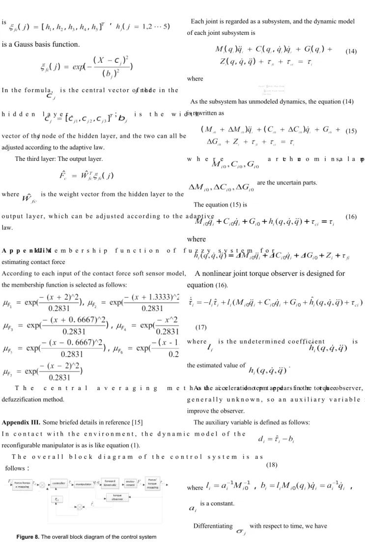
T h e o v e r a l l b l o c k d i a g r a m o f t h e c o n t r o l s y s t e m i s a s follows:
Figure 8. The overall block diagram of the control system
Each joint is regarded as a subsystem, and the dynamic model of each joint subsystem is
(14)
where
As the subsystem has unmodeled dynamics, the equation (14) is rewritten as
(15)
w h e r e a r e t h e n o m i n a l p a r ts, a n d
are the uncertain parts.
The equation (15) is
(16)
where
A nonlinear joint torque observer is designed for equation (16).
(17)
w h e r e i s t h e u n d e t e r m i n e d c o e f f i c i e n t, i s
the estimated value of .
As the acceleration term appears in the torque observer, it is
g e n e r a l l y u n k n o w n , s o a n a u x i l i a r y v a r i a b l e i s i n t r o d u c e d t o improve the observer.
The auxiliary variable is defined as follows:
(18)
where
,
,
is a constant.
Improved torque observer is
(19)
U n d e r t h e p r e m i s e o f t h e o b s e r v a t i o n e r r o r i s u n i f o r m l y ultimately bounded in the equation (19),the Jacobian matrix can
realize the conversion between the force and torque, and finally