_________________________________________________________________
5/17/2005 System Programming Section Page 1
System Programming Section... 3
General Defaults ... 4
(Mode 01) System Password ... 4
(Mode 02) Clock Display Format... 5
(Mode 03) Automatic Night Transfer on Weekends ... 6
(Mode 04) Conference Tone... 7
(Mode 05) Transfer Call on Hook Down... 7
(Mode 06) Headset Operation ... 7
(Mode 07) Local Digit Length... 9
(Mode 08) Set Voice Mail Wake-up ... 9
(Mode 09) System Date & Time ... 9
Feature Access Codes ... 11
(Mode 15) Operator Access Code ... 11
(Mode 16) Trunk Hunt Group Access Code... 13
(Mode 17) Trunk Hunt Group 8 Access Code... 14
(Mode 18) Dial 7 Feature Access Code... 14
(Mode 19) Intercom Call Access Code ... 14
Tenant Service ... 16
(Mode 20) Trunk Tenant Service ... 16
(Mode 21) Station Tenant Service... 18
(Mode 22) Tenant Operators ... 19
(Mode 23) Unrestricted Tenant Intercom Access... 21
System Alarms ... 22
(Mode 30) Weekday System Alarms... 22
(Mode 31) Saturday System Alarms... 24
(Mode 32) Sunday System Alarms... 24
(Mode 33) Station Alarm Duration... 25
(Mode 34) DVA Port... 26
Paging ... 28
(Mode 35) Zone Paging Port Assignment ... 28
(Mode 36) Page Tone ... 30
(Mode 37) Page Music Source ... 31
Dry Contact Relay Control... 32
(Mode 40) Dry Contact Relay Control ... 32
(Mode 41) Dry Contact Relay Default ... 33
Door Phone... 35
(Mode 45) Door Phone Ring Group 1 ... 35
(Mode 46) Door Phone Ring Group 2 ... 37
(Mode 47) Door Phone Ring Time... 37
Voice Mail Interface ... 39
(Mode 50) Voice Mail Station Hunt Group (9) ... 39
(Mode 51) Use Voice Mail Inband Signaling... 41
(Mode 52) Voice Mail Inband Signaling Packets... 42
(Mode 53) Voice Mail Trunk Incoming Call Packets ... 42
(Mode 54) Inband Signaling DTMF Tone Length ... 43
Inband Signaling 2... 44
(Mode 55) Use Inband Signaling 2... 44
(Mode 56) Inband Signaling Packets 2... 44
(Mode 57) Trunk Incoming Call Packets 2 ... 44
Toll Restriction ... 45
(Mode 60) Station Toll Plan Assignment - Day ... 46
(Mode 61) Station Toll Plan Assignment - Night... 47
_________________________________________________________________
5/17/2005 System Programming Section Page 2
(Mode 63) Speed Dial Toll Restriction Break Point... 49
(Mode 64) Check-In Call Restriction ... 50
(Mode 70) Common Restricted Numbers... 52
(Mode 71) Common Unrestricted Numbers ... 53
(Mode 72) Long Distance Call Prefix ... 53
(Mode 73) Digit Length Restriction ... 55
(Mode 74) Class-of-Restriction - Trunk ... 56
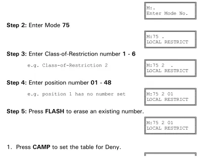
(Mode 75) Local Call Restriction ... 58
(Mode 76) Long Distance Call Restriction... 60
(Mode 77) PABX Trunk Access Code ... 62
(Mode 78) Ignore PABX Access Code ... 63
Automatic Route Selection... 64
(Mode 80) Use Automatic Route Selection... 64
(Mode 81) Force ARS ... 65
(Mode 82) Automatic Route Selection Time-out ... 66
(Mode 83) Area Code Table... 67
(Mode 84) Office Code Table ... 69
(Mode 85) Route Table... 70
(Mode 86) Time Period ... 71
(Mode 87) Holiday Table ... 74
_________________________________________________________________
5/17/2005 System Programming Section Page 3
System Programming Section
System Programming is divided into three separate sections for ease of access.
The sections are Trunk Programming Section, Station Programming Section,
and System Programming Section.
System Programming Section has been grouped into categories.
•
General
Defaults
•
Feature
Access
Codes
• Tenant Service
• System Alarms
• Paging
• External Relay Controls
•
Door
Phone
• Voice Mail Interface
• Inband Signaling 2
•
Toll
Restriction
_________________________________________________________________
5/17/2005 System Programming Section Page 4
General Defaults
(Mode 01) System Password
The System Password is used when accessing System Programming.
The System Password is a combination of up to six keys (0 - 9,
*, #).
Refer to the start of the
Programming Guide
on how to enter System
Programming.
Programming Procedure:
Step 1:
Enter Programming Mode by Pressing
[PROG-PROG-1-2-3-HOLD]
from any Display phone.
╔════════════════╗
║M:. ║
║Enter Mode No. ║
╚════════════════╝
Step 2:
Enter Mode
01
╔════════════════╗
e.g Default password ║M:01 123 ║
║PASSWORD ║
╚════════════════╝
Step 3:
Press
FLASH
to erase an existing or default password.
╔════════════════╗
║M:01 ║
║PASSWORD ║
╚════════════════╝
Step 4:
Enter new password (up to 6 keys).
╔════════════════╗
e.g. Enter key combination ║M:01 #92*13║
║PASSWORD ║
╚════════════════╝
Step 5:
Press
HOLD
to save new password.
╔════════════════╗
║*:01 #92*13║
║PASSWORD ║
_________________________________________________________________
5/17/2005 System Programming Section Page 5
(Mode 02) Clock Display Format
The clock display on LCD Keyphones can be set to either 12 Hour or 24 Hour
format. This mode also sets the format used with the SMDR output of Call
Records.
See (System Programming Section - Mode 09) System Date & Time for how to
change the system date and time.
Programming Procedure:
Step 1:
Enter Programming Mode by Pressing
[PROG-PROG-1-2-3-HOLD]
from any Display phone.
╔════════════════╗
║M:. ║
║Enter Mode No. ║
╚════════════════╝
Step 2:
Enter Mode
02
╔════════════════╗
║M:02 24 HOUR║
║CLOCK FORMAT ║
╚════════════════╝
Step 3:
Press
MSG
for 12 Hour or
FLASH
for 24 Hour.
╔════════════════╗
e.g. Set to 12 Hour format ║M:02 12 HOUR║
║CLOCK FORMAT ║
╚════════════════╝
Step 4:
Press
HOLD
to save change.
╔════════════════╗
║*:02 12 HOUR║
║CLOCK FORMAT ║
_________________________________________________________________
5/17/2005 System Programming Section Page 6
(Mode 03) Automatic Night Transfer on Weekends
When the system using Night Service has been set to use Automatic Night
Transfer for automatically switching between Day Mode and Night Mode, it is
often undesirable to have the system stay in Night Mode on weekends.
The system can be set to ignore Automatic Night Transfer on weekends.
Thus, when the system switches to Night Mode on Friday, it stays in Night
Mode until switching to Day Mode on Monday.
Note:
Automatic Night Transfer on Weekends has no affect when Night
Service is set using Manual Night Transfer.
Refer to the
Easy Reference Guide
on how to set Night Service and Automatic
Night Transfer.
Programming Procedure:
Step 1:
Enter Programming Mode by Pressing
[PROG-PROG-1-2-3-HOLD]
from any Display phone.
╔════════════════╗
║M:. ║
║Enter Mode No. ║
╚════════════════╝
Step 2:
Enter Mode
03
╔════════════════╗
║M:03 NO║
║WEEKEND TRANSFER║
╚════════════════╝
Step 3:
Press
MSG
(Yes) for stay in Night Mode or
FLASH
(No) for Night
Transfer.
╔════════════════╗
e.g. Set to stay in Night Mode ║M:03 YES║
for weekend. ║WEEKEND TRANSFER║
╚════════════════╝
Step 4:
Press
HOLD
to save change.
╔════════════════╗
║*:03 YES║
║WEEKEND TRANSFER║
_________________________________________________________________
5/17/2005 System Programming Section Page 7
(Mode 04) Conference Tone
When a Conference is established by a Station a Tone can be used to signal to
the parties in the Conference that they are in a Conference. The Conference
Tone is generated once every 32 seconds. (
MSG
= Yes = Conference Tone)
Programming Procedure:
See (System Programming Section - Mode 03) Automatic Night Transfer on
Weekends for how to set Conference Tone.
(Mode 05) Transfer Call on Hook Down
To transfer a Trunk or Station to another Station, the call is first put on hold,
the receiving Station is called, then the
TRF
key is pressed to transfer the
Trunk or Station. An alternate method is available which merely involves
hanging up to actually do the transfer instead of pressing the
TRF
key.
(
MSG
= Yes = Transfer on Hook Down,
FLASH
= No = Press
TRF
key to
transfer)
Programming Procedure:
See (System Programming Section - Mode 03) Automatic Night Transfer on
Weekends for how to set Transfer Call on Hook Down.
(Mode 06) Headset Operation
Individual Keyphones can be set to work with Headset Operation. Headset
Operation is switched On and Off from each individual Keyphone. All
Keyphones can be restricted from setting Headset operation.
(
MSG
= Yes = Allow Stations to be set for Headset Operation)
Note:
Only certain types of Keyphone can use Headset operation. Headset
Operation also stops the Keyphone from being used in Handsfree mode.
Refer to the
Special Feature Section - Headset Operation
on how to set
_________________________________________________________________
5/17/2005 System Programming Section Page 8
Programming Procedure:
_________________________________________________________________
5/17/2005 System Programming Section Page 9
(Mode 07) Local Digit Length
When using the KDX-T1 Card the system can be set up for 10 digit local
dialing. To ensure proper outbound dialing from the KDX-T1 card.
(
MSG
= Yes = Allow 10-digit dialing out over the KDX-T1 card)
Programming Procedure:
See (System Programming Section - Mode 03) Automatic Night Transfer on
Weekends for how to set Headset Operation.
(Mode 08) Set Voice Mail Wake-up
When using the 742 dial code for wake-up the system can be set to
automatically call the Voice mail with integration to allopw the end user to
enter their wake-up call through the Mailbox.
(
MSG
= Yes = Allow Wake-up feature through Voice Mail)
Programming Procedure:
See (System Programming Section - Mode 03) Automatic Night Transfer on
Weekends for how to set Headset Operation.
(Mode 09) System Date & Time
The System is equipped with a real-time clock.
The real-time clock is used for setting the start time of Trunk Calls and for the
date and time displayed on the LCD displays.
_________________________________________________________________
5/17/2005 System Programming Section Page 10
Refer to the
Easy Reference Guide
on how to set the System Date and Time
from the Console or Second Console.
Day of Week (0 = Sun, 1 = Mon, 2 = Tues, 3 = Wed, 4 = Thurs, 5 = Fri,
6 = Sat)
Programming Procedure:
Step 1:
Enter Programming Mode by Pressing
[PROG-PROG-1-2-3-HOLD]
from any Display phone.
╔════════════════╗
║M:. ║
║Enter Mode No. ║
╚════════════════╝
Step 2:
Enter Mode
09
╔════════════════╗
e.g. The current Date is shown. ║M:09 1 ║
║Date 98/01/01║
╚════════════════╝
Step 3:
Enter new Date - must be
YYMMDD
╔════════════════╗
e.g. 981108 for 8th November 1998 ║M:09 1 ║
║Date 98/11/08║
╚════════════════╝
Step 4:
Display automatically changes.
Enter new Time - must be
HHMM
(In 24 Hour format)
╔════════════════╗
e.g. 1547 for 3:47 in the afternoon. ║M:09 2 ║
║Time 15:47║
╚════════════════╝
Step 5:
Display automatically changes.
Enter Day of Week
0 - 6
╔════════════════╗
e.g. 4 for Thursday ║M:09 3 ║
║Day of Week Thu║
╚════════════════╝
Step 6:
Press
HOLD
at any stage to save a change.
╔════════════════╗
║*:09 3 ║
║Day of Week Thu║
_________________________________________________________________
5/17/2005 System Programming Section Page 11
Feature Access Codes
There are five Feature Access Codes that can be set to customize the system
operation for users. These codes can be changed to allow flexibility in Station
numbering schemes. The Feature Access Codes are listed by priority below:
•
Operator
Access
Code
• Trunk Hunt Group Access Code
•
Trunk
Hunt
Group 8 Access Code
• Dial 7 Feature Access Code
• Intercom Call Access Code
(Mode 15) Operator Access Code
When a Station calls the Operator the call will ring the Tenant Operator, a
Station from a Station Hunt Group or the Console(s). The access code for
calling the Operator can be programmed. If 0 is used for the Operator Access
Code then 0 should not be set for any other access code.
See (Station Programming Section - Mode 50) Console and (Station
Programming Section - Mode 51) Second Console for how to set a Station as
the Console.
See (Station Programming Section) Operator Destination for how to set an
alternate Operator for the Operator Stations.
See (System Programming Section - Mode 22) Tenant Operators for how to
set an Operator for a Tenant Group.
Programming Procedure:
Step 1:
Enter Programming Mode by Pressing
[PROG-PROG-1-2-3-HOLD]
from any Display phone.
╔════════════════╗
║M:. ║
║Enter Mode No. ║
_________________________________________________________________
5/17/2005 System Programming Section Page 12
Step 2:
Enter Mode
15
╔════════════════╗
e.g. “o” is the default code. ║M:15 0║
║OPERATOR ACCESS ║
_________________________________________________________________
5/17/2005 System Programming Section Page 13
Step 3:
Press
FLASH
to clear.
╔════════════════╗
║M:15 ║
║OPERATOR ACCESS ║
╚════════════════╝
Step 4:
Enter new access code
0 - 9, *, #
╔════════════════╗
e.g. Set 1 for Operator Access ║M:15 1║
║OPERATOR ACCESS ║
╚════════════════╝
Step 5:
Press
HOLD
to save change.
╔════════════════╗
║*:15 1║
║OPERATOR ACCESS ║
╚════════════════╝
(Mode 16) Trunk Hunt Group Access Code
Automatic Trunk Selection can be done by dialing an access code. If 9 is used
for the Trunk Hunt Group Access Code then 9 should not be set for any other
access code.
When accessing a Trunk Hunt Group, either the Trunk Hunt Group assigned to
the Station is automatically used, or a second digit (1 - 8) must be dialed to
specify which Trunk Hunt Group to use.
See (Trunk Programming Section - Mode 50) Trunk Hunt Group Programming
for how to set up Trunk Hunt Groups.
See (Station Programming Section - Mode 74) Trunk Hunt Group Assignment
for how to set the default Trunk Hunt Group for a Station.
Programming Procedure:
_________________________________________________________________
5/17/2005 System Programming Section Page 14
(Mode 17) Trunk Hunt Group 8 Access Code
A second Trunk Hunt Group Access Code is provided for accessing Trunk Hunt
Group 8. If 8 is used for the Trunk Hunt Group 8 Access Code then 8 should
not be set for any other access code.
See (Trunk Programming Section - Mode 50) Trunk Hunt Group Programming
for how to set up Trunk Hunt Groups.
Programming Procedure:
See (System Programming Section - Mode 15) Operator Access Code for how
to set the Trunk Hunt Group 8 Access Code.
(Mode 18) Dial 7 Feature Access Code
A number of features are available to each Station which all start with the
same access code. This allows the features to be accessed by Single-line
Telephones. If 7 is used for the Dial 7 Feature Access Code then 7 should not
be set for any other access code.
Refer to the
Easy Reference Guide
on how to use the Dial 7 Features from a
Station.
See (Station Programming Section) Station Class-of-Service for how to restrict
Dial 7 Features to Stations.
Programming Procedure:
See (System Programming Section - Mode 15) Operator Access Code for how
to set the Dial 7 Feature Access Code.
(Mode 19) Intercom Call Access Code
A Intercom Call Access Code can be set for access Stations. If a Intercom
Access Code is set than it must be dialed to provide access to Station
numbers.
_________________________________________________________________
5/17/2005 System Programming Section Page 15
Programming Procedure:
_________________________________________________________________
5/17/2005 System Programming Section Page 16
Tenant Service
(Mode 20) Trunk Tenant Service
Up to eight Tenants can be supported on the same system. Stations can be
restricted to accessing Trunks with the same Tenant number. 0 means the
Trunk is unrestricted and can be accessed by any Station.
Programming Procedure:
Step 1:
Enter Programming Mode by Pressing
[PROG-PROG-1-2-3-HOLD]
from any Display phone.
╔════════════════╗
║M:. ║
║Enter Mode No. ║
╚════════════════╝
Step 2:
Enter Mode
20
╔════════════════╗
║M:20 . ║
║TRUNK TENANT ║
╚════════════════╝
Step 3:
Enter Trunk number
01 - 96
╔════════════════╗
e.g. Trunk 1 ║M:20 01 2║
║TRUNK TENANT ║
╚════════════════╝
Step 4:
Press
FLASH
to clear (an existing Tenant number).
╔════════════════╗
║M:20 1 0║
║TRUNK TENANT ║
╚════════════════╝
Step 5:
Enter new Tenant number
1 - 8
╔════════════════╗
e.g. Set Trunk 1 to Tenant 3 ║M:20 1 3║
║TRUNK TENANT ║
╚════════════════╝
Step 6:
Press
HOLD
to save change.
╔════════════════╗
║*:20 1 3║
║TRUNK TENANT ║
╚════════════════╝
_________________________________________________________________
5/17/2005 System Programming Section Page 17
╔════════════════╗
e.g. Move to next Trunk ║M:20 2 0║
║TRUNK TENANT ║
_________________________________________________________________
5/17/2005 System Programming Section Page 18
(Mode 21) Station Tenant Service
Up to eight Tenants can be supported on the same system. Stations can be
restricted to calling Stations with the same Tenant number. 0 means the
Station is unrestricted and can be called by any Station.
Programming Procedure:
Step 1:
Enter Programming Mode by Pressing
[PROG-PROG-1-2-3-HOLD]
from any Display phone.
╔════════════════╗
║M:. ║
║Enter Mode No. ║
╚════════════════╝
Step 2:
Enter Mode
21
╔════════════════╗
║M:21 . ║
║STATION TENANT ║
╚════════════════╝
Step 3:
Enter Port number
001 - 400
╔════════════════╗
e.g. Port 12 has not been assigned a ║M:21 12 0║
Tenant number. ║ ST:12 ║
╚════════════════╝
Step 4:
Press
FLASH
to clear (an existing Tenant number).
╔════════════════╗
║M:21 12 0║
║ ST:12 ║
╚════════════════╝
Step 5:
Enter new Tenant number
1 - 8
╔════════════════╗
e.g. Set Station 12 to Tenant 3 ║M:21 12 3║
║ ST:12 ║
╚════════════════╝
Step 6:
Press
HOLD
to save change.
╔════════════════╗
║*:21 12 3║
║ ST:12 ║
╚════════════════╝
Step 7:
(Optional)
Press
TRF
to scroll forward to next Port or MIC to move
backward to previous Port. Repeat from Step 4.
╔════════════════╗
e.g. Move to next Station ║M:21 13 0║
║ ST:13 ║
_________________________________________________________________
5/17/2005 System Programming Section Page 19
(Mode 22) Tenant Operators
Each Tenant can be assigned a different Station to ring when the Operator is
called. The Tenant Operator does not have to be assigned the same Tenant
number. The Station assigned as Tenant Operator has priority over the
assigned system Operator. If no Tenant Operator is assigned then the system
Operator is used.
See (Station Programming Section - Mode 50) Console and (Station
Programming Section - Mode 51) Second Console for how to set a Station as
the Console.
See (Station Programming Section) Operator Destination for how to set an
alternate Operator for the Operator Stations.
Programming Procedure:
Step 1:
Enter Programming Mode by Pressing
[PROG-PROG-1-2-3-HOLD]
from any Display phone.
╔════════════════╗
║M:. ║
║Enter Mode No. ║
╚════════════════╝
Step 2:
Enter Mode
22
╔════════════════╗
║M:22 . ║
║TENANT OPERATORS║
╚════════════════╝
Step 3:
Enter Tenant number
1 - 8
╔════════════════╗
e.g. Tenant 3 ║M:22 3 ║
║TENANT OPERATORS║
╚════════════════╝
Step 4:
Press
FLASH
to clear (an existing Station Port).
╔════════════════╗
║M:22 3 ║
║TENANT OPERATORS║
╚════════════════╝
Step 5:
Enter new Station Port
1 - 400
╔════════════════╗
e.g. Set Tenant 3 Operator to ║M:22 3 21║
Station port 021. ║TENANT OPERATORS║
╚════════════════╝
Step 6:
Press
HOLD
to save change.
╔════════════════╗
║*:22 3 21║
║TENANT OPERATORS║
_________________________________________________________________
5/17/2005 System Programming Section Page 20
Step 7:
(Optional) Press
TRF
to scroll forward to next Tenant or
MIC
to move
backward to previous Tenant. Repeat from Step 4.
╔════════════════╗
e.g. Move to next Tenant. ║M:22 4 ║
║TENANT OPERATORS║
_________________________________________________________________
5/17/2005 System Programming Section Page 21
(Mode 23) Unrestricted Tenant Intercom Access
Each Tenant is restricted from calling Stations assigned to other Tenants.
Each Tenant can be set for unrestricted Intercom access.
Intercom restriction does not apply when calling Operator Stations.
See (Station Programming Section) Operator Destination for how to set an
alternate Operator for the Operator Stations.
Programming Procedure:
Step 1:
Enter Programming Mode by Pressing
[PROG-PROG-1-2-3-HOLD]
from any Display phone.
╔════════════════╗
║M:. ║
║Enter Mode No. ║
╚════════════════╝
Step 2:
Enter Mode
23
╔════════════════╗
║M:23 . ║
║TENANT INTERCOM ║
╚════════════════╝
Step 3:
Enter Tenant number
1 - 8
╔════════════════╗
e.g. Tenant 5 ║M:23 5 NO║
║TENANT INTERCOM ║
╚════════════════╝
Step 4:
Press
MSG
for Intercom access (Yes) or
FLASH
(No) for No Intercom
access.
╔════════════════╗
e.g. Set Tenant 5 Stations to ║M:23 5 YES║
unrestricted Intercom access. ║TENANT INTERCOM ║
╚════════════════╝
Step 5:
Press
HOLD
to save change.
╔════════════════╗
║*:23 5 YES║
║TENANT INTERCOM ║
╚════════════════╝
Step 6
: (Optional) Press
TRF
to scroll forward to next Tenant number or
MIC
to
move backward to previous Tenant number. Repeat from Step 4.
╔════════════════╗
e.g. Move to next Tenant ║M:23 6 NO║
║TENANT INTERCOM ║
_________________________________________________________________
5/17/2005 System Programming Section Page 22
System Alarms
There are three sets of System Alarms, each effective during a specific time of
the week. Monday to Friday inclusive (Mode 30), Saturday (Mode 31), and
Sunday (Mode 32).
(Mode 30) Weekday System Alarms
There can be up to eight System Alarms set for the weekdays (effective for
Monday to Friday inclusive). A System Alarm puts the Background Music over
the External Paging Port and through the Keyphone speakers.
See (Station Programming Section - Mode 07) Ring for System Alarm for how
to stop the System Alarm for individual Keyphones.
Refer to the
Easy Reference Guide
for how to set Station Alarms.
Programming Procedure:
Step 1:
Enter Programming Mode by Pressing
[PROG-PROG-1-2-3-HOLD]
from any Display phone.
╔════════════════╗
║M:. ║
║Enter Mode No. ║
╚════════════════╝
Step 2:
Enter Mode
30
╔════════════════╗
║M:30 . ║
║SYS ALARMS ║
╚════════════════╝
Step 3:
Enter Alarm number
1 - 8
╔════════════════╗
e.g. Alarm 1 is currently not set ║M:30 1 00:00║
║SYS ALARMS 0║
╚════════════════╝
Step 4:
Press
FLASH
to clear (an existing Alarm).
╔════════════════╗
║M:30 1 00:00║
║SYS ALARMS 0║
╚════════════════╝
Step 5:
Enter new Alarm Time (must be HHMM in 24 Hour format).
_________________________________________________________________
5/17/2005 System Programming Section Page 23
e.g. 1725 for 5:25 in the afternoon. ║M:30 1 17:25║
║SYS ALARMS 0║
_________________________________________________________________
5/17/2005 System Programming Section Page 24
Step 6:
Enter Alarm duration
1 - 9999
seconds
╔════════════════╗
e.g. Set to 15 seconds. ║M:30 1 17:25║
║SYS ALARMS 15║
╚════════════════╝
Step 7:
Press
HOLD
to save change.
╔════════════════╗
║*:30 1 17:25║
║SYS ALARMS 15║
╚════════════════╝
Step 8:
Move to next alarm. Press
MIC
to scroll backward,
TRF
to scroll
forward.
╔════════════════╗
e.g. Move to next alarm ║M:30 2 00:00║
No Alarm has been set. ║SYS ALARMS 0║
╚════════════════╝
(Mode 31) Saturday System Alarms
There can be up to eight System Alarms set for Saturday. A System Alarm
puts the Background Music over the External Paging Port and through the
Keyphone speakers.
Programming Procedure:
See (System Programming Section - Mode 30) Weekday System Alarms and
follow the programming procedure to set Saturday System Alarms.
(Mode 32) Sunday System Alarms
There can be up to eight System Alarms set for Sunday. A System Alarm puts
the Background Music over the External Paging Port and through the Keyphone
speakers.
Programming Procedure:
_________________________________________________________________
5/17/2005 System Programming Section Page 25
(Mode 33) Station Alarm Duration
The duration for a Station to ring for a Wake-Up / Remind Call can be set.
The Station Alarm Duration can be set from 10 to 9999 seconds.
Refer to the
Easy Reference Guide
for how to set Station Wake-Up / Remind
Calls.
See (Station Programming Section - Mode 39) Set Wake-up / Remind Calls for
how to restrict a Station from setting a Wake-up / Remind Call.
See (Operator Feature Section) Hotel Features for how to set a Wake-up /
Remind Call for a Station from an Operator Station.
Programming Procedure:
Step 1:
Enter Programming Mode by Pressing
[PROG-PROG-1-2-3-HOLD]
from any Display phone.
╔════════════════╗
║M:. ║
║Enter Mode No. ║
╚════════════════╝
Step 2:
Enter Mode
33
╔════════════════╗
e.g. Station Alarm Time is ║M:33 25║
25 seconds. ║ST ALARM TIME ║
╚════════════════╝
Step 3:
Press
FLASH
to clear (an existing time).
╔════════════════╗
║M:33 0║
║ST ALARM TIME ║
╚════════════════╝
Step 4:
Enter Station Alarm Time
10 - 9999
╔════════════════╗
e.g. Set Station Alarm Time to ║M:33 30║
30 seconds. ║ST ALARM TIME ║
╚════════════════╝
Step 5:
Press
HOLD
to save change.
╔════════════════╗
║*:33 30║
║ST ALARM TIME ║
_________________________________________________________________
5/17/2005 System Programming Section Page 26
(Mode 34) DVA Port
When a Station has been set up with a Wake-up / Remind Call the Station will
ring at the programmed time. When answered the Station will receive either
music or be connected to the DVA Port. If there is no assigned DVA Port or if
the DVA Port is busy then the Station will only get music.
A Station Hunt Group can also be assigned as the DVA Port. Only one Station
from the Station Hunt Group will be selected.
Refer to the
Easy Reference Guide
for how to set Station Wake-Up / Remind
Calls.
See (Station Programming Section - Mode 39) Set Wake-up / Remind Calls for
how to restrict a Station from setting a Wake-up / Remind Call.
See (Operator Feature Section) Hotel Features for how to set a Wake-up /
Remind Call for a Station from an Operator Station.
Programming Procedure:
Step 1:
Enter Programming Mode by Pressing
[PROG-PROG-1-2-3-HOLD]
from any Display phone.
╔════════════════╗
║M:. ║
║Enter Mode No. ║
╚════════════════╝
Step 2:
Enter Mode
34
╔════════════════╗
║M:34 ║
║DVA PORT ║
╚════════════════╝
Step 3:
Press
FLASH
to erase (an existing Station Port or Station Group).
╔════════════════╗
║M:34 ║
║DVA PORT ║
╚════════════════╝
Step 4:
Enter a new Station Port
001 - 400
╔════════════════╗
e.g. Set to Port 013 ║M:34 13║
║DVA PORT ║
╚════════════════╝
OR
Press
MSG
for Station Hunt Group
1 - 9
╔════════════════╗
e.g. Set to Station Hunt Group 1 ║M:34 STGP:1║
║DVA PORT ║
_________________________________________________________________
5/17/2005 System Programming Section Page 27
Step 5:
Press
HOLD
to save change.
╔════════════════╗
║*:34 13║
║DVA PORT ║
_________________________________________________________________
5/17/2005 System Programming Section Page 28
Paging
(Mode 35) Zone Paging Port Assignment
There can be up to eight Zones assigned for External Paging. The eighth Zone
is the External Paging connection built into the system. The other seven Zones
use normal Station Ports.
Refer to the
Easy Reference Guide
for how to do Paging.
Programming Procedure:
Step 1:
Enter Programming Mode by Pressing
[PROG-PROG-1-2-3-HOLD]
from any Display phone.
╔════════════════╗
║M:. ║
║Enter Mode No. ║
╚════════════════╝
Step 2:
Enter Mode
35
╔════════════════╗
║M:35 . ║
║ZONE PAGE ASSIGN║
╚════════════════╝
Step 3:
Enter Zone number
1 - 7
╔════════════════╗
e.g. Zone 1 is currently set to ║M:35 1 26║
Port 26. ║ZONE PAGE ASSIGN║
╚════════════════╝
Step 4:
Press
FLASH
to erase (an existing Port number).
╔════════════════╗
║M:35 1 ║
║ZONE PAGE ASSIGN║
╚════════════════╝
Step 5:
Enter new Port number
001 - 400
╔════════════════╗
e.g. Set to Port 65 ║M:35 1 65║
║ZONE PAGE ASSIGN║
╚════════════════╝
Step 6:
Press
HOLD
to save change.
╔════════════════╗
║*:35 1 65║
║ZONE PAGE ASSIGN║
╚════════════════╝
_________________________________________________________________
5/17/2005 System Programming Section Page 29
╔════════════════╗
e.g. Move to next Zone ║M:35 2 ║
No Port has been set ║ZONE PAGE ASSIGN║
_________________________________________________________________
5/17/2005 System Programming Section Page 30
(Mode 36) Page Tone
When making a Paging Call, a tone can be given at the start to announce the
Paging Call.
Refer to the
Easy Reference Guide
for how to do Paging.
Programming Procedure:
Step 1:
Enter Programming Mode by Pressing
[PROG-PROG-1-2-3-HOLD]
from any Display phone.
╔════════════════╗
║M:. ║
║Enter Mode No. ║
╚════════════════╝
Step 2:
Enter Mode
36
╔════════════════╗
║M:36 NO║
║PAGE TONE ║
╚════════════════╝
Step 3:
Press
MSG
(Yes) for Page Tone or
FLASH
(No) for none.
╔════════════════╗
e.g. Set to use Page Tone ║M:36 YES║
║PAGE TONE ║
╚════════════════╝
Step 4:
Press
HOLD
to save change.
╔════════════════╗
║*:36 YES║
║PAGE TONE ║
_________________________________________________________________
5/17/2005 System Programming Section Page 31
(Mode 37) Page Music Source
There are three music sources available to the External Paging Output, one
internal and two external. The two external music sources each require an
external music source to be connected to the system.
Refer to the
Installation Guide
for more information on connecting an External
Music Source.
Refer to the
Easy Reference Guide
for how to do Paging.
Programming Procedure:
Step 1:
Enter Programming Mode by Pressing
[PROG-PROG-1-2-3-HOLD]
from any Display phone.
╔════════════════╗
║M:. ║
║Enter Mode No. ║
╚════════════════╝
Step 2:
Enter Mode
37
╔════════════════╗
║M:37 1║
║PAGE MUSIC SOURC║
╚════════════════╝
Step 3:
Press
1
(internal),
2
(external 1), or
3
(external 2).
╔════════════════╗
e.g. Set to External Music Source 1 ║M:37 2║
║PAGE MUSIC SOURC║
╚════════════════╝
Step 4:
Press
HOLD
to save change.
╔════════════════╗
║*:37 2║
║PAGE MUSIC SOURC║
_________________________________________________________________
5/17/2005 System Programming Section Page 32
Dry Contact Relay Control
(Mode 40) Dry Contact Relay Control
There are 6 programmable Dry Contact Relays located on the KDX-MDF. They
can be used in conjunction with Station Ports, Trunk Lines, Loud Bells 1-4,
Zone paging, Music on Hold Power Control 1-2 or Door Lock control.
Refer to
Installation Manual
for more information on connecting Dry Contact
Relays.
Programming Procedure:
Step 1:
Enter Programming Mode by Pressing
[PROG-PROG-1-2-3-HOLD]
from any Display phone.
╔════════════════╗
║M:. ║
║Enter Mode No. ║
╚════════════════╝
Step 2:
Enter Mode
40
╔════════════════╗
║M:40 . ║
║DRY CONTACT CTRL║
╚════════════════╝
Step 3:
Enter a Dry Contact Relay
1 - 6
╔════════════════╗
e.g. Enter Dry Contact Relay 1 ║*:40 1 ║
║DRY CONTACT CTRL║
╚════════════════╝
Step 4:
Enter Station Port
001 - 460
or Press
MSG
to Scroll through the other
options.
╔════════════════╗
e.g. Press MSG “once” for TK ║M:40 1 TK:01║
Enter 01 for Trunk 01 ║DRY CONTACT CTRL║
╚════════════════╝
Step 5:
Press
HOLD
to save change.
╔════════════════╗
e.g. Dry Contact Relay 1 is ║*:40 1 TK:01║
set for Trunk 1 ║DRY CONTACT CTRL║
╚════════════════╝
Step 6
: (Optional) Press
TRF
to scroll forward to next Dry Contact Relay or
MIC
to move backward to previous Dry Contact Relay. Repeat from
_________________________________________________________________
5/17/2005 System Programming Section Page 33
╔════════════════╗
e.g. Move to next Dry Contact Relay ║M:40 2 ║
║DRY CONTACT CTRL║
╚════════════════╝
(Mode 41) Dry Contact Relay Default
The 6 Dry Contacts Relays can be programmed to be normally open or
normally closed.
Refer to
Installation Manual
for more information on connecting Dry Contact
Relays.
Programming Procedure:
Step 1:
Enter Programming Mode by Pressing
[PROG-PROG-1-2-3-HOLD]
from any Display phone.
╔════════════════╗
║M:. ║
║Enter Mode No. ║
╚════════════════╝
Step 2:
Enter Mode
41
╔════════════════╗
║M:41 . ║
║DRY CONTACT DEF.║
╚════════════════╝
Step 3:
Enter Dry Contact Relay
1 – 6
.
╔════════════════╗
e.g. Enter “1” for Dry Contact Relay 1 ║M:41 1 OPEN║
Default is “OPEN”. ║DRY CONTACT DEF.║
╚════════════════╝
Step 4:
Press
FLASH
for Closed or
MSG
for Open.
╔════════════════╗
e.g. Changed to Closed ║*:41 1 CLOSED║
║DRY CONTACT DEF.║
╚════════════════╝
Step 5:
Press
HOLD
to save change.
╔════════════════╗
e.g. Dry Contact Relay 1 is closed ║*:41 1 CLOSED║
║DRY CONTACT DEF.║
╚════════════════╝
Step 6
: (Optional) Press
TRF
to scroll forward to next Dry Contact Relay or
MIC
to move backward to previous Dry Contact Relay. Repeat from
_________________________________________________________________
5/17/2005 System Programming Section Page 34
╔════════════════╗
e.g. Move to next Dry Contact Relay ║M:41 2 OPEN║
║DRY CONTACT DEF.║
_________________________________________________________________
5/17/2005 System Programming Section Page 35
Door Phone
(Mode 45) Door Phone Ring Group 1
When a Station is set to work as a Door Phone, a ring group of Station Ports
need to be assigned. Lifting the handset automatically rings the Station Ports
assigned to Ring Group 1. All Station Ports in Ring Group 1 will ring if idle.
See (Station Programming Section - Mode 32) Ring Door Phone Group 1 for
how to set a Station Port to work as a Door Phone Port.
Programming Procedure:
Step 1:
Enter Programming Mode by Pressing
[PROG-PROG-1-2-3-HOLD]
from any Display phone.
╔════════════════╗
║M:. ║
║Enter Mode No. ║
╚════════════════╝
Step 2:
Enter Mode
45
╔════════════════╗
║M:45 . ║
║DOOR RING GP 1 ║
╚════════════════╝
Step 3:
Enter position number
01 - 16
╔════════════════╗
e.g. No port has been set for ║M:45 01 26║
position 1 ║DOOR RING GP 1 ║
╚════════════════╝
Step 4:
Press
FLASH
to erase (an existing Port number).
╔════════════════╗
║M:45 01 ║
║DOOR RING GP 1 ║
╚════════════════╝
Step 5:
Enter new Port number
1 - 400
╔════════════════╗
e.g. Set to Port 65. ║M:45 01 65║
║DOOR RING GP 1 ║
╚════════════════╝
Step 6:
Press
HOLD
to save change.
╔════════════════╗
║*:45 01 65║
║DOOR RING GP 1 ║
╚════════════════╝
_________________________________________________________________
5/17/2005 System Programming Section Page 36
╔════════════════╗
e.g. Move to next position ║M:45 02 ║
No Port has been set ║DOOR RING GP 1 ║
_________________________________________________________________
5/17/2005 System Programming Section Page 37
(Mode 46) Door Phone Ring Group 2
When a Station is set to work as a Door Phone, a ring group of Station Ports
need to be assigned. Lifting the handset automatically rings the Station Ports
assigned to Ring Group 2. All Station Ports in Ring Group 2 will ring if idle.
See (Station Programming Section - Mode 33) Ring Door Phone Group 2 for
how to set a Station Port to work as a Door Phone Port.
Programming Procedure:
See (System Programming Section - Mode 45) Door Phone Ring Group 1 and
follow the programming procedure for setting Door Phone Ring Group 2.
(Mode 47) Door Phone Ring Time
The Ring Time for a dedicated Door Phone can be set from 5 to 60 seconds.
The Door Phone will ring Door Phone Group 1.
See (Station Programming Section – Mode 32) Ring Door Phone Group 1 and
(Station Programming Section – Mode 33) Ring Door Phone Group 2 for how
to set a normal Station as a Door Phone.
Programming Procedure:
Step 1:
Enter Mode 47
╔════════════════╗
║M:47 10║
║DPHONE RING TIME║
╚════════════════╝
Step 2:
Press
FLASH
to clear an existing time.
╔════════════════╗
║M:47 0║
║DPHONE RING TIME║
╚════════════════╝
Step 3:
Enter new Door Phone ring time.
╔════════════════╗
e.g. Set to Port 15. ║M:47 15║
║DPHONE RING TIME║
╚════════════════╝
Step 4:
Press
HOLD
to save change.
╔════════════════╗
║*:47 15║
_________________________________________________________________
5/17/2005 System Programming Section Page 38
_________________________________________________________________
5/17/2005 System Programming Section Page 39
Voice Mail Interface
(Mode 50) Voice Mail Station Hunt Group (9)
The system has nine Station Hunt Groups. The first eight are regular Station
Hunt Groups that can be used for many purposes while Station Hunt Group 9
is used specifically for Voice Mail.
See (Station Programming Section - Mode 60) Station Hunt Groups for how to
set a normal Station Hunt Group.
Refer to the
Easy Reference Guide
on how to access a Station Hunt Group.
Programming Procedure:
Step 1:
Enter Programming Mode by Pressing
[PROG-PROG-1-2-3-HOLD]
from any Display phone.
╔════════════════╗
║M:. ║
║Enter Mode No. ║
╚════════════════╝
Step 2:
Enter Mode
50
╔════════════════╗
║M:50 . ║
║VM ST HUNT GROUP║
╚════════════════╝
Step 3:
Enter a memory position
01 – 16 Note:
The memory position is a
counter to keep track of how many ports have been entered, up to
16 ports can be assigned.
╔════════════════╗
e.g. The fourth position is not set. ║M:50 04 ║
║VM ST HUNT GROUP║
╚════════════════╝
Step 4:
Press
FLASH
to clear (an existing Station Port number).
╔════════════════╗
║M:50 04 ║
║VM ST HUNT GROUP║
╚════════════════╝
Step 5:
Enter new Station Port number
001 - 400
╔════════════════╗
e.g. Set to Port 21. ║M:50 04 21║
║VM ST HUNT GROUP║
╚════════════════╝
Step 6:
Press
HOLD
to save change.
_________________________________________________________________
5/17/2005 System Programming Section Page 40
║*:50 04 21║
║VM ST HUNT GROUP║
_________________________________________________________________
5/17/2005 System Programming Section Page 41
Step 7:
(Optional) Press
TRF
to scroll forward to next position or MIC to move
backward to previous position. Repeat from Step 4.
╔════════════════╗
e.g. Move to next position ║M:50 05 ║
║VM ST HUNT GROUP║
╚════════════════╝
(Mode 51) Use Voice Mail Inband Signaling
When using Voice Mail with the system, integration between the Voice Mail
and system can be either SMDI or Inband Signaling.
Refer to the
Installation Guide
for more information on connecting a Voice Mail
system.
Programming Procedure:
Step 1:
Enter Programming Mode by Pressing
[PROG-PROG-1-2-3-HOLD]
from any Display phone.
╔════════════════╗
║M:. ║
║Enter Mode No. ║
╚════════════════╝
Step 2:
Enter Mode
51
╔════════════════╗
║M:51 NO║
║USE VM INBAND ║
╚════════════════╝
Step 3:
Press
MSG
(YES) for Inband Signaling or
FLASH
(No) for none.
╔════════════════╗
e.g. Set to use Inband Signaling ║M:51 YES║
║USE VM INBAND ║
╚════════════════╝
Step 4:
Press
HOLD
to save change.
╔════════════════╗
║*:51 YES║
║USE VM INBAND ║
_________________________________________________________________
5/17/2005 System Programming Section Page 42
(Mode 52) Voice Mail Inband Signaling Packets
This mode is currently not used. It will be available in later versions of
software.
(Mode 53) Voice Mail Trunk Incoming Call Packets
_________________________________________________________________
5/17/2005 System Programming Section Page 43
(Mode 54) Inband Signaling DTMF Tone Length
The Inband Signaling DTMF Tone Length can be set from 50 ms to 250 ms (n
x 10 ms).
The Inband Signaling DTMF Tone Length determines how quickly the DTMF is
generated for Inband Signaling. Setting the DTMF Tone Length too short
results in the device receiving the Inband Signaling to miss digits or ignore the
Inband Signaling completely.
Programming Procedure:
Step 1:
Enter Programming Mode by Pressing
[PROG-PROG-1-2-3-HOLD]
from any Display phone.
╔════════════════╗
║M:. ║
║Enter Mode No. ║
╚════════════════╝
Step 2:
Enter Mode
54
╔════════════════╗
e.g. Currently set to 100 ms ║M:54 10║
║INBAND DTMF LEN ║
╚════════════════╝
Step 3:
Press
FLASH
to clear (an existing length).
╔════════════════╗
║M:54 0║
║INBAND DTMF LEN ║
╚════════════════╝
Step 4:
Enter new DTMF Tone Length
5 - 250
.
╔════════════════╗
e.g. Set to 80 ms (n = 8) ║M:54 8║
║INBAND DTMF LEN ║
╚════════════════╝
Step 5:
Press
HOLD
to save change.
╔════════════════╗
║*:54 8║
║INBAND DTMF LEN ║
╚════════════════╝
_________________________________________________________________
5/17/2005 System Programming Section Page 44
Inband Signaling 2
(Mode 55) Use Inband Signaling 2
This mode is currently not used. It will be available in later versions of
software.
(Mode 56) Inband Signaling Packets 2
This mode is currently not used. It will be available in later versions of
software.
(Mode 57) Trunk Incoming Call Packets 2
_________________________________________________________________
5/17/2005 System Programming Section Page 45