A New Method for Mitigation SEU Errors in
Three-Dimensional FPGAs
Mona Nassehi Osgooi
1, Azadeh Abkar
2Faculty Member, Karoon Higher Institute, Ahwaz, Khuzestan, Iran 1
Faculty Member, Karoon Higher Institute, Ahwaz, Khuzestan, Iran2
ABSTRACT: Now a day's one of the most crucial issues in the field of FPGAGs, especially in SRAM FPGAs is single event upsets. One of the most effective methods to decrease these errors is using three dimensional FPGAs. This paper presents evaluation and mitigation of SEU cost on six layers three-dimensional (3D) FPGAs. The evaluation results show that SUE rate decrease about 67% on six layers 3D FPGAs. We also estimate the SEU cost improvement due to changing the place of 6 layers on 3D FPGAs, and it shows 28% improvements. However because of the importance of Trough Silicon Vias (TSVs) on delay estimation, we tried to make a trade-off between total TSV length and SEU costs.
KEYWORDS: Single Event Upset (SEU), Three-dimensional FPGAs, Total TSV length. I. INTRODUCTION
A field programmable gate array (FPGA) is a flexible and reusable design alternative to costume integrated systems. The basic FPGA architecture consist of symmetrical array of user-configurable logic blocks and reprogrammable interconnections, which consist of wire segments and switch boxes [2], [3]. However this flexibility often comes with substantial performance cost. And on the other hand interconnect delay causes FPGA speed to be slower than the other ASIC designs for the same circuits [4], [8].
Another issue in field of field programmable gate arrays is soft errors. Soft errors which was a concern for space application in the past, become a concerning issues at ground level. Alpha particles and atmospheric neutrons cause single-event upset (SEU). Nowadays one of the most important concerns on FPGAs is these single events upsets [5]. Recently the concept of three-dimensional FPGAs was proposed with the idea of overcoming all these issues. 3D FPGAs replace a lot of long interconnections with short interconnects. And also provide layered architecture, which is useful to overcome SEU issues [6].
This paper considers the modelling and evaluation in [1], and proposed new layered placement to improve SEU cost, and also proposed a trade-off between total TSV length and SEU costs. The experimental results show that by means of six layers 3D systems, we can reduce SEU cost up to 73%. This improvement can be achieved, since the SEU effects are limited on middle layers of 3D FPGAs. In our studies we compare four layers and six layers 3D FPGAs. Also we improve SEU cost on 3D FPGAs by changing the place of most SEU affected layers, so we improve 3D FPGAs SEU cost up to 28%.
Paper is organized as follows. Section II describes the different method of evaluation and mitigation of SEU errors by means of CAD algorithms. Section III describes SEU on FPGAs. Section IV discusses evaluation and mitigation of SEU in 3D FPGAs. Section V presents the experimental results. Finally, last section concludes the paper.
II. RELATEDWORK
(TMR). Although TMR technique decreases the SEU effects significantly, but it causes high performance at the same time.
Another research in this field is [7], which mitigates SEUs by means of placement and routing algorithms. In that paper the VPR tool is modified so that placement and routing are used but the algorithms are SEU avoidance.
The other work in this field is [1], which is used the VPR and TPR placement algorithms to evaluate SEU errors on three dimensional FPGAs. In this work, they used the SEU errors equations for conventional FPGAs and extend it for three dimensional FPGAs.
III.SEU IN FPGAS
Nano metric technologies are sensitive to radiation that may happen both in space environment and at the ground level. Soft errors which was a concern for space application in the past, become a concerning issues at ground level. Alpha particles and atmospheric neutrons cause single-event upset (SEU). Neutrons create soft errors in an indirect manner. A high energy neutron may interact with silicon, oxygen, or other atoms of chip. Thermal neutrons may also cause soft errors. In storage cell (memory cells, flip-flops, and ...), a strong pulse will reverse the cell state. And it will cause Single Event Upset [5]. This is one of the most popular soft errors. Unfortunately, packaging couldn't effectively solve this problem. Since SEUs are made of neutrons which pass through packaging easily. Nowadays one of the most important concerns on FPGAs, especially SRAM FPGAs, is these single events upsets. So our circuits should be aware of these errors.
One of the most practical methods of evaluation SEU costs is mentioned in [7] that evaluate SEU rate by means of placement the FPGAs components. The effects of SEU on FPGAs routing resources can be classified like this: Short fault, Open fault, Bridging fault.
They use this metrics to evaluate the SEU cost like this:
SEU Cost = .Short Fault Cost + .Open Fault Cost + .Bridging Fault Cost
(1)
Where the three different types of SEU cost component can be controlled by user defined α, β, and𝛿 . But in this study we consider all these three multiplications the same. The short fault cost should be defined in a way that the numbers of programmable switches causing a short to non-usage nets decrease. So by means of Eq. (2) we decrease the nets' length inside of the FPGA. We use the fallowing Eq. to determine the short fault cost in our study:
1
Short Fault Cost = ( ). ( ) ( ) nets
N
x y
i
q i bb i bb i
(2)
Where 𝑁𝑛𝑒𝑡𝑠 shows the number of nets, 𝑞 𝑖 is used to determine the net terminal numbers, 𝑏𝑏𝑥 𝑖 and 𝑏𝑏𝑦(𝑗) are x
and y dimensions of bounding box of net i. For open fault cost again they consider nets' length, because in short wires the probability of open faults is very low. So for open fault cost again we use Eq. (2).
For bridging fault cost we should consider the overlapping between the bonding boxes of two nets. And the common region between every two nets bonding boxes should be decreased. This can be defined by Eq. (3):
𝐵𝑟𝑖𝑑𝑔𝑖𝑛𝑔 𝑓𝑎𝑢𝑙𝑡 𝑐𝑜𝑠𝑡 = 𝑞 𝑖 . 𝑞 𝑗 . 𝑐𝑏𝑏𝑥 𝑖, 𝑗 + 𝑐𝑏𝑏𝑦(𝑖, 𝑗) 𝑁𝑛𝑒𝑡𝑠
𝑖≠𝑗 ,𝑖≠𝑗 𝑁𝑛𝑒𝑡𝑠
𝑖=1
(3)
Where 𝑞 𝑖 and 𝑞 𝑗 are the number of terminals for net i and net j, respectively. 𝑐𝑏𝑏𝑥(𝑖, 𝑗) And 𝑐𝑏𝑏𝑦(𝑖, 𝑗) are the
IV.EVALUATION AND MITIGATION OF SEU IN 3D FPGAS
The extended model of SEU cost for three dimensional FPGAs is proposed in this section. Then we use these equations to compare the SEU rate on four and six layers 3D FPGAs.
As we mentioned before in [7] there is a SEU cost equation, which they use it to make VPR tools, SEU aware. This equation consists of three elements, short fault cost, open fault cost, bridging fault cost. In [1] we extend this equation for evaluating the SEU cost on three-dimensional FPGAs. Where the three different types of SEU cost component can be controlled by user defined α, β, and𝛿 . But in this study we consider all these three multiplications the same. The short fault cost should be defined in a way that the numbers of programmable switches causing a short to non-usage nets decrease. So by means of Eq. (4) we decrease the nets' length inside of the FPGA. We use the fallowing Eq. to determine the short fault cost in our study:
1 1
3 . ( )
Layers
N Nnets
x y
l i
DSFM DF l q i bb i bb i
(4)
Where 𝑁𝐿𝑎𝑦𝑒𝑟𝑠 is the number of 3DFPGAs layers, and 𝐷𝐹 𝑙 is the multiplication that shows Neutron effects in each
layer.
As mentioned in [6] depth of Neutron electron holes on Silicon is about 5.3µm, and it shows that the central regions of ICs are somehow the most safety regions. So we allocate lower multiplications to the central layers. And from the central layers to the first and last layer, this multiplication is decreased. In this paper without considering the substrate effect, the same multiplications are allocated to the first and last layers. Since, we may use these ICs, out of the earth atmosphere.
For open fault metrics (OFM), we use the same equation with short fault metrics (SFM). Because in both of them interconnect length play the most important role for evaluations.
For bridging fault cost, we use Eq. (3), which mentioned in the previous section. And we extend it like this:
1 1 1,
3 , ,
layers nets nets
N N N
x y
l i j j i
DBFM DF l q i q j cbb i j cbb i j
(5)
At last with replacing the above value in the proceeding equation, we can evaluate the total SEU costs.
SEU Metric = .3 DSFM 3DOFM 3DBFM
(6)
For evaluating SEU metrics in conventional FPGAs, VPR routing file is used. And for three dimensional FPGAs, TPR routing file is used. However, TPR is designed for placement and routing three dimensional FPGAs.
In this paper we proposed a new model for improving the SEU metrics in three dimensional FPGAs. In this method we replace the most SEU affected layers with central layers. Since neutron electron holes is limited at the central layers, as mentioned before. In this way we allocate the lower multiplication for these layers.
Then we use the Z parameters, which is used in channel z of TPR routing files, to determine the number of TSVs between each two layers. Though with the advent of total TSV length and SEU metrics, we proposed a trade of between them. First of all we evaluate the SEU metrics for any kind of layers placement, by means of Eq. (4, 5, and 6). On the other hand by means of number of TSV between each two layers, we determine the total TSV length for each type of layers placement. At last we use Eq. (7), which mentioned below, to calculate the minimum product of these two criteria.
Optimization of this parameter is important for us, because, having the minimum SEU metrics is our main goal. And on the other hand minimum total TSV length cause minimum propagation delay. Reducing propagation delay is really important in the industry, and with this optimization, we achieve this goal.
V. EXPERIMENTAL RESULTS
In order to evaluate the result of this technique, we have applied this algorithm to 10 MCNC benchmarks. We use the VPR and TPR routing files of these benchmarks to compare SEU metrics on conventional FPGAs and 4 and 6 layers three dimensional FPGAs.
It is important to mention that, we have done this experiments under the condition that, there isn’t any thermal issue for three dimensional FPGAs, if we consider the thermal issues, the results may be different. On the other hand, we do not change the architecture of TSVs, and the placement of TSVs is the same as what the TPR designed.
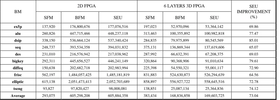
We use MCNC benchmarks to create the TPR routing files for six layers three dimensional FPGAs. Then we evaluate SEU metrics for six layers 3D FPGAs. The results of this experiments are compared with four layers 3D FPGAs and conventional FPGAs. You can see the experimental result on table 1. As mentioned before because open fault metrics and short fault metrics are somehow the same, we don’t show open fault metrics in our tables. As you can see in table 1, the SEU metrics on six layers 3D FPGAs improved up to 73% in comparison with conventional FPGAs. So we can conclude that three dimensional integration, with more layers can optimize SEU costs on field programmable gate arrays.
TABLE I: SEU ERROR METRIC IN 2D AND SIX LAYERS 3D FPGAS
BM
2D FPGA 6 LAYERS 3D FPGA SEU
IMPROVEMENT (%)
SFM BFM SEU SFM BFM SEU
ex5p 137,920 176,800,676 177,076,516 197,023 52,970,096 53,364,142 69.86
alu 260,826 447,715,466 448,237,118 313,463 100,355,892 100,982,818 77.47
dsip 338,150 536,664,124 537,340,424 284,835 79,975,899 80,545,569 85.01
seq 248,737 393,534,358 394,031,832 375,131 136,869,344 137,619,606 65.07
des 231,010 216,576,942 217,038,962 287,992 66,632,391 67,208,375 69.03
bigkey 292,311 445,656,527 446,241,149 320,864 90,368,906 91,010,634 79.61
diffeq 150,638 202,682,718 202,983,994 225,398 54,550,321 55,001,117 72.90
frisc 562,197 1,484,057,425 1,485,181,819 831,883 524,630,873 526,294,639 64.56
elliptic 615,138 2,051,473,413 2,052,703,689 858,897 556,927,722 558,645,516 72.78
tseng 93,827 97,820,427 98,008,081 138,851 25,087,134 25,364,836 74.12
Average 293,075 605,298,208 605,884,358 383,434 168,836,858 169,603,725 73.04
TABLE II: SEU ERROR METRIC MITIGATION ON FOUR LAYERS 3D FPGAS BY LAYER ASIGNMENT
BM
4LAYERS 3D FGPGA SEU METRICS BEFORE LAYER ASIGNMENT
4LAYERS 3D FGPGA SEU METRICS AFTER
LAYER ASIGNMENT SEU IMPROVEMENT (%)
SFM BFM SEU SFM BFM SEU SFM BFM SEU
ex5p 212,588 79,741,634 80,166,810 153,625 55,551,978 55,859,228 27.74 30.34 30.32
alu 352,358 179,254,526 179,959,242 264,481 129,769,781 130,298,743 24.94 27.61 27.60
dsip 322,640 131,356,780 132,002,060 239,998 93,194,830 93,674,826 25.61 29.05 29.04
seq 437,576 240,475,468 241,350,620 323,664 175,303,466 175,950,794 26.03 27.10 27.10
des 331,180 112,097,024 112,759,384 284,313 81,989,250 82,557,876 14.15 26.86 26.78
bigkey 378,452 162,345,076 163,101,980 334,076 116,950,262 117,618,414 11.73 27.96 27.89
diffeq 274,150 102,312,984 102,861,284 202,305 74,985,212 75,389,822 26.21 26.71 26.71
frisc 940,008 849,418,096 851,298,112 696,040 619,108,830 620,500,910 25.95 27.11 27.11
elliptic 998,252 970,851,462 972,847,966 730,312 696,518,978 697,979,602 26.84 28.26 28.25
tseng 154,774 37,436,440 37,745,988 111,599 25,595,557 25,818,755 27.90 31.63 31.60
Average 440,198 286,528,949 287,409,345 334,041 206,896,814 207,564,897 23.71 28.26 28.24
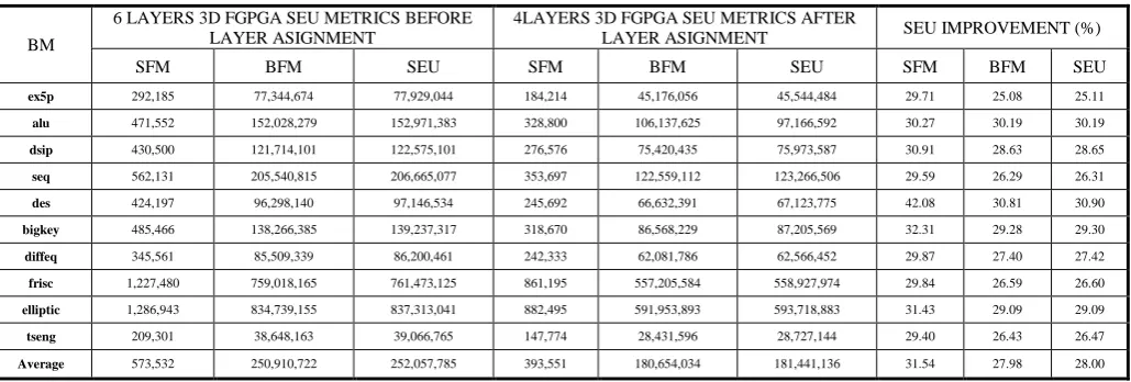
TABLE III: SEU ERROR METRIC MITIGATION ON SIX LAYERS 3D FPGAS BY LAYER ASIGNMENT
BM
6 LAYERS 3D FGPGA SEU METRICS BEFORE LAYER ASIGNMENT
4LAYERS 3D FGPGA SEU METRICS AFTER
LAYER ASIGNMENT SEU IMPROVEMENT (%)
SFM BFM SEU SFM BFM SEU SFM BFM SEU
ex5p 292,185 77,344,674 77,929,044 184,214 45,176,056 45,544,484 29.71 25.08 25.11
alu 471,552 152,028,279 152,971,383 328,800 106,137,625 97,166,592 30.27 30.19 30.19
dsip 430,500 121,714,101 122,575,101 276,576 75,420,435 75,973,587 30.91 28.63 28.65
seq 562,131 205,540,815 206,665,077 353,697 122,559,112 123,266,506 29.59 26.29 26.31
des 424,197 96,298,140 97,146,534 245,692 66,632,391 67,123,775 42.08 30.81 30.90
bigkey 485,466 138,266,385 139,237,317 318,670 86,568,229 87,205,569 32.31 29.28 29.30
diffeq 345,561 85,509,339 86,200,461 242,333 62,081,786 62,566,452 29.87 27.40 27.42
frisc 1,227,480 759,018,165 761,473,125 861,195 557,205,584 558,927,974 29.84 26.59 26.60
elliptic 1,286,943 834,739,155 837,313,041 882,495 591,953,893 593,718,883 31.43 29.09 29.09
tseng 209,301 38,648,163 39,066,765 147,774 28,431,596 28,727,144 29.40 26.43 26.47
Average 573,532 250,910,722 252,057,785 393,551 180,654,034 181,441,136 31.54 27.98 28.00
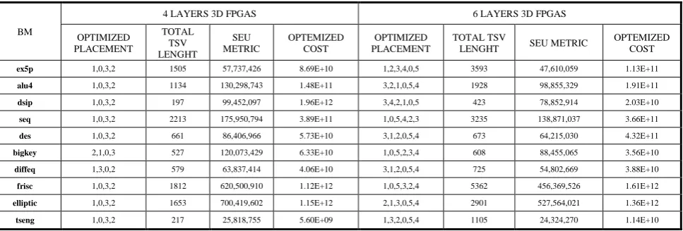
In the following, we first evaluate the total TSV length for the best way of layer placement, which minimize the SEU metrics. Then we evaluate SEU metrics for the best layers placement, which decrease the total TSV length. For the second evaluation, we design a function that compare the entire possible three dimensional FPGA layers placement, and report the minimum total TSV length and its layers placement. In four and six layers 3D FPGAs there are 24 and 720 different layers placement respectively. We tried to make a trade of between total TSV length, and SEU metrics. Since total TSV length, has great effect on propagation delay.
TABLE IV: TRADE OF BETWEEN SEU ERROR METRIC AND TOTAL TSV LENGTH
BM
4 LAYERS 3D FPGAS 6 LAYERS 3D FPGAS
OPTIMIZED PLACEMENT
TOTAL TSV LENGHT
SEU METRIC
OPTEMIZED COST
OPTIMIZED PLACEMENT
TOTAL TSV
LENGHT SEU METRIC
OPTEMIZED COST
ex5p 1,0,3,2 1505 57,737,426 8.69E+10 1,2,3,4,0,5 3593 47,610,059 1.13E+11
alu4 1,0,3,2 1134 130,298,743 1.48E+11 3,2,1,0,5,4 1928 98,855,329 1.91E+11
dsip 1,0,3,2 197 99,452,097 1.96E+12 3,4,2,1,0,5 423 78,852,914 2.03E+10
seq 1,0,3,2 2213 175,950,794 3.89E+11 1,0,5,4,2,3 3235 138,871,037 3.66E+11
des 1,0,3,2 661 86,406,966 5.73E+10 3,1,2,0,5,4 673 64,215,030 4.32E+11
bigkey 2,1,0,3 527 120,073,429 6.33E+10 1,0,5,2,3,4 608 88,455,065 3.56E+10
diffeq 1,3,0,2 579 63,837,414 4.06E+10 3,1,2,0,5,4 725 54,802,669 3.88E+10
frisc 1,0,3,2 1812 620,500,910 1.12E+12 1,0,5,3,2,4 5362 456,369,526 1.61E+12
elliptic 1,0,3,2 1653 700,419,602 1.15E+12 2,1,3,0,5,4 2901 527,564,021 1.36E+12
tseng 1,0,3,2 217 25,818,755 5.60E+09 1,3,2,0,5,4 1105 24,324,270 1.14E+10
VI.CONCLUSION
In this paper, we proposed a new method for evaluation and mitigation of SEU cost on six layers three-dimensional FPGAs, by means of suitable layers assignment. As the depth of neutron electron holes is restricted, the central layers in 3D FPGAs have lower SEU cost in comparison with other layers. So we shift the most SEU cost layers to the central layers, and decrease the SEU cost, totally. We analysed the effect of this method on 10 MCNC benchmarks. The experimental results show that SEU cost on six layers three-dimensional FPGAs improved about 28%. Then due to the importance of TSV length on delay estimation, we make a trade of between SEU cost, and total TSV length.
REFRENCES
[1] M. Nassehi, A. Jahanian, and H. R. Zarandi, "Modeling, Evaluation and Mitigation of SEU Error in Three-Dimensional FPGAs, "In CSI International Symposium on Computer Architecture and Digital Systems (CADS), 2012.
[2] R. Le, S. Reda and R. Iris Bahar, “High-performance, cost effective 3D FPGA architectures,” In proc.of the 2009 ACM/GLSVLSI, pp.251-256, 2009.
[3] M. J. Alexander, J. P. cohoon, J. L. Ganley, and G. Robins, “Placement and routing for performance-oriented FPGA layout,” VLSI Design: an international journal of custom-chip design, simulation and testing, 7(1), 1998.
[4] I. Kuon, R. Tessier, and J. Rose, “FPGA architecture: survey and challenges", foundations and trends in electronic design automation, Vol. 2, No. 2, pp.135–253, 2007.
[5] R. J. Nikolic, C. E. Reinhardt, C. Li Cheng, and T. F. Wang, “Roadmap for high efficiency Solid-state neutron detectors,” In Proceeding of SPIE, Vol. 6013, Oct 2005.
[6] M. J. Alexander, J. P. Cohoon, J. L. Colflesh, J. Karo, and G. Robines, “Three-Dimensional Field Programmable Gate array,” in ASIC Conference and Exhibit, 1995, proc. of the Eight annual IEEE International, pp.253-256, sep.1995.
[7] H. R. Zarandi, S.G. Miremadi, D. K. Pradhan, and J. Mathew, “SEU-mitigation placement and routing algorithms and their impact in SRAM-based FPGAs,” In Proc. of the 8th International Symposium on quality electronic design, IEEE, 2007.
[8] W. M. Meleis, M. Leeser, P. M. Zavracky, and M. M. Vai, “Architectural design of a three dimensional FPGA,”In Proc. IEEE, pp. 256-268, 1997.