INTRODUCTION
About this guideThis guide is designed to help you plan and configure a TalkSwitch multi-location network for Voice over IP (VoIP).
NOTE: For TalkSwitch provisioning with a VoIP service provider, please refer to the documentation located on our website www.talkswitch.com.
Who should use this guide
This guide is intended for customers who have:
•
Purchased the TalkSwitch 48-CVA phone system and wish to configure it to use VoIP.•
Upgraded their existing TalkSwitch 48-CA phone system with a VoIP module (thereby converting it to a TalkSwitch 48-CVA) and wish to configure it to use VoIP.Where to go for further information
The guides listed below, as well as other guides, can be found in the TalkSwitch folder in the Windows Start menu, on the TalkSwitch software CD, and in the support section of our website at www.talkswitch.com/support.
•
For information on the initial installation and setup of a TalkSwitch phone system, refer to the TalkSwitch Start Guide.•
For additional information on VoIP functionality and advanced configuration, refer to the TalkSwitch User Guide for the TalkSwitch 48-CVA.•
For information on installing a VoIP module, refer to the VoIP Module Installation Guide.Troubleshooting
The TalkSwitch system and the configuration software are designed for ease of use. However, if you encounter difficulties with the installation or configuration of your TalkSwitch:
•
Consult the documents in the TalkSwitch folder on your PC or on the TalkSwitch software CD.•
Access additional TalkSwitch information online, including FAQs and Quick Guides, atwww.talkswitch.com/support.
Contacting TalkSwitch Technical Support
•
Contact your reseller.BEFORE YOU BEGIN
Before you configure your TalkSwitch system to make and receive VoIP calls, review the network planning information provided in this section.
Ensure there is a TalkSwitch 48-CVA or VoIP gateway in each location
In order to create a multi-location VoIP network, a TalkSwitch 48-CVA or a VoIP gateway, such as a Mediatrix®
2102, is required at each location. The Mediatrix 2102 is a TalkSwitch-certified third-party SIP gateway that can be used by small branch offices or teleworkers.Note: Check with TalkSwitch Support before purchasing third-party SIP devices to ensure they operate with TalkSwitch.
Each location in a multi-location network can support up to 4 TalkSwitch 48-CVA units, with a maximum of 32 local extensions and 16 VoIP lines per location. You can contact TalkSwitch Support for assistance in setting up large multi-location networks.
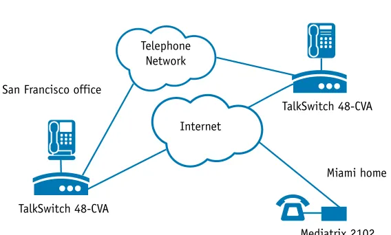
The following is an example of a multi-location network where two locations are equipped with TalkSwitch systems and a teleworker is equipped with a Mediatrix 2102 device. TalkSwitch and the Mediatrix 2102 route VoIP calls over the Internet, while local calls are routed over the traditional telephone network.
FIGURE 1.Multi-location network with VoIP calling San Francisco office
New York office
Miami home
TalkSwitch 48-CVA
TalkSwitch 48-CVA
Mediatrix 2102 Telephone
Network
Ensure TalkSwitch is connected to a LAN and IP network
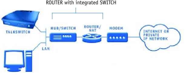
In order to make and receive VoIP calls, ensure the TalkSwitch system in each location is connected to a Local Area Network (LAN), consisting of a PC (for configuration purposes), Ethernet switch and router, or a router with an integrated switch (such as the Linksys BEFSR81).
Note: For optimal performance, you will need a reliable high-speed broadband Internet connection in each location. ‘Lite’ broadband connections are not suitable for simultaneous voice and data traffic.
FIGURE 2.TalkSwitch network configuration
Uncertain of your VoIP call capacity? Visit our website at:
www.talkswitch.com/voip/voip_capacity.php to perform a VoIP Bandwidth Test, which will determine your VoIP call capacity based on your current Internet connection speed.
Prioritizing voice traffic
If you plan on sharing your Internet connection among your computers and TalkSwitch (between data and voice), then it is critical that the voice traffic has priority over the data traffic. Some routers, such as the Linksys BEFSR81, support Quality of Service routing (QoS) for this purpose. If your router supports QoS, ensure that it is configured to provide priority to voice traffic (see your router documentation for configuration details).
Forwarding voice data through a router/firewall
In order to pass through a router’s firewall, voice data received by your network must be mapped to the appropriate TalkSwitch unit. TalkSwitch uses UPnP (Universal Plug and Play) to automate the mapping of firewall ports for forwarding VoIP data. Many of today’s routers support UPnP for port mapping/forwarding. If your router supports UPnP, ensure that it is enabled (see your router documentation for configuration details).
If a router does not support UPnP, you will need to configure it to map specific ports to TalkSwitch. The following describes which ports to map to TalkSwitch:
•
To allow SIP Signaling data* to be forwarded to TalkSwitch, firewall port 5060 mustbe mapped to the TalkSwitch unit known as the Local Proxy. By default, this is the lowest numbered 48-CVA unit on a LAN. For example, if TalkSwitch unit 1 is a 48-CVA unit, then port 5060 should be mapped to this unit. SIP Signaling is done using UDP.
Note: The IP Configuration window of the TalkSwitch Software indicates (with an asterix) which TalkSwitch unit is acting as the Local Proxy (see Step 1 of this guide — Configure TalkSwitch to make VoIP calls).
•
In order for voice traffic to be forwarded to TalkSwitch, corresponding ports must be mapped to each TalkSwitch 48-CVA unit. The following table shows the firewall ports to map to each TalkSwitch 48-CVA unit on a LAN.•
If you plan on configuring TalkSwitch remotely, you will need to map port 9393 to the TalkSwitch unit that is being configured. For information on configuring TalkSwitch remotely, refer to the TalkSwitch Remote Configuration Quick Guide. Configuration is done using TCP.For information on configuring a router for port forwarding, visit http://www.portforward.com/routers.htm.
TalkSwitch with DSL Internet service
If a location has DSL Internet service, ensure that the router’s Point-to-Point Protocol over Ethernet
(
PPPoE) settings are configured for connecting to the Internet service. Refer to the documentation provided with the router and check with the Internet Service Provider (ISP) for configuration information.* The Session Initiation Protocol (SIP) Signaling data initiates a VoIP session in an IP network.
TABLE 1. Firewall portsa required open for VoIP communication with TalkSwitch
a. The port numbers shown are the reserved default port numbers. To re-assign these numbers, contact TalkSwitch Technical Support.
Determine which TalkSwitch will act as the SIP server for your
VoIP network
The TalkSwitch 48-CVA has a built-in Session Initiation Protocol (SIP) server to manage all SIP devices in a TalkSwitch multi-location network. The TalkSwitch system designated as the SIP server will contain the registration information for all other systems and SIP devices in the network. When making or receiving a VoIP call, a device will register with the SIP server, which will then route the call to the appropriate location.
Note: If interfacing TalkSwitch with a VoIP Service Provider, the Service Provider will act as the SIP server for your network.
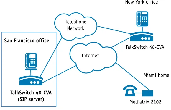
In the following example, the TalkSwitch system in the San Francisco office is designated as the SIP server. When a VoIP call is placed from any location, the phone number is resolved by the SIP server and the call is routed to the appropriate office.
FIGURE 3.Multi-location network with designated SIP server
New York office
TalkSwitch 48-CVA
(SIP server) Mediatrix 2102
Internet
San Francisco office
Miami home TalkSwitch 48-CVA Telephone
Which location and TalkSwitch system should I configure as the SIP server? Any TalkSwitch 48-CVA system in a multi-location network can act as the SIP server. However, we recommend that the location have a static, rather than a dynamic, public IP address. Since a static IP address is fixed and does not change, a consistent connection can be kept among all locations and the SIP server.
If having a static IP address is not possible, you can obtain a Fully Qualified Domain Name (FQDN) from a Dynamic Domain Name Service (DDNS) provider. One such provider is DynDNS. A DDNS handles dynamic IP address changes and maps IP addresses to your FQDN, thereby making IP address changes transparent to TalkSwitch. Check which DDNS your router can support. For more information on DynDNS, visit:
http://www.dyndns.org/services/dyndns.
Note: Only one TalkSwitch system in a multi-location VoIP network should be designated as the SIP server.
Configuring TalkSwitch to act as the SIP server is described in Step 2 of this guide — Configure TalkSwitch to act as the SIP Server.
For more information about the SIP server and for information on optimizing your IP network for VoIP, refer to the TalkSwitch Installation and User Guide for the
TalkSwitch 48-CVA.
Establish a dialing plan for your network
Since you are creating a private VoIP network, you must assign phone numbers to VoIP trunks (lines) in TalkSwitch. A form has been provided in this guide to help you record a dialing plan for your network (see Appendix A — TalkSwitch VoIP Network
Administration Form).
Choosing phone numbers for VoIP lines
Each TalkSwitch 48-CVA unit supports 4 VoIP lines. Up to 3 phone numbers can be assigned to each of the 4 lines so that unique call handling scenarios can be configured for up to 12 numbers per unit. Phone numbers for VoIP lines can be 3 or more digits in length.
TalkSwitch supports 50VoIP location numbers (250 to 299) that permit direct dialing from any extension or Auto Attendant. Numbers outside of this range can also be assigned to VoIP lines and accessed using Hunt Groups. Note: Each phone number assigned to a VoIP line must be unique in a multi-location network. Assigning phone numbers to VoIP lines is described in Step 4 of the configuration section of this guide — Assign Phone Numbers to VoIP Lines.
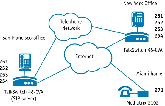
In the following example, four VoIP location numbers are assigned to VoIP lines in San Francisco (251 to 254), four are assigned to VoIP lines in New York (261 to 264), and one is assigned to the residential office in Miami (271). These phone numbers can be dialed directly from an extension or from an Auto Attendant from any location within the network.
FIGURE 4.Multi-location network with assigned phone numbers New York Office
Internet
Miami home San Francisco office
STEP 1 – CONFIGURE TALKSWITCH TO MAKE VOIP CALLS
Each TalkSwitch system in a multi-location network must be configured with both local IP and public IP address information. These addresses are used to direct VoIP calls to the appropriate location. Each TalkSwitch unit in a system will have a different local IP address.Set the TalkSwitch local IP address
The following steps describe how to set the local IP address(es) of a TalkSwitch system:
1. Open the TalkSwitch configuration software by double-clicking the TalkSwitch icon on your Desktop or, from the Windows Start menu, select Programs, the TalkSwitch folder, and click TalkSwitch.
2. In the TalkSwitch System Configuration window, selectSystem Information and then IP Configuration from the menu at the left.
3. TalkSwitch is factory configured to use DHCP (Dynamic Host Configuration Protocol) to automatically obtain its System IP Settings. If the location has a DHCP server, which is typically a function of the router, the fields on the screen will automatically be filled in with the correct IP information. Click Use the following IP and DNS information to ‘lock in’ these settings and ensure they are saved as the system IP settings.
4. If the location does not have a DHCP server, the System IP Settings fields will not be filled in. Click Use the following IP and DNS information and enter the IP address(es), Subnet mask, Default Gateway, Preferred DNS Server, and Alternate DNS Server information in the appropriate fields. For details on these settings refer to the TalkSwitch Installation and User Guide for the 48-CVA.
Note: Unit 1 IP Address designates the local IP address of TalkSwitch unit 1. If there are multiple units in a system, enter the IP addresses of all units in the system (Unit 2 IP Address, Unit 3 IP Address, Unit 4 IP Address).
4
Set the TalkSwitch public IP address
The public IP address of a TalkSwitch system is assigned by your Internet Service Provider. Depending on the type of service, you will either have a dynamic or static IP address. If you are unsure which type you have, contact your Internet Service Provider.
The following steps describe how to set the public IP address of a TalkSwitch system:
1. Specify the Type of Public WAN IP for Internet Connection by selecting either dynamic or static from the drop-down list.
If this TalkSwitch system will act as the SIP server for a network, we recommend having a static Public IP address. For more information on the SIP server, refer to Determine which TalkSwitch system will act as the SIP server for your VoIP network in the Before you Begin section of this guide.
2. If this TalkSwitch system will act as the SIP server for a network and has a dynamic Public IP address, enter the Fully Qualified Domain Name (FQDN) associated with the Public IP address. If the address is static, leave this field blank.
You can obtain a FQDN from a Dynamic Domain Name Service (DDNS) provider such as DynDNS (visit http://www.dyndns.org/services/dyndns). Check which DDNS your router can support.
STEP 2 – CONFIGURE TALKSWITCH TO ACT AS THE SIP SERVER
The following steps describe how to configure a TalkSwitch system to act as the SIP server (Redirect Proxy/Registrar). Only one TalkSwitch system in a multi-location network can be configured as the SIP server. For information on the SIP server, see Determine which TalkSwitch system will act as the SIP server for your VoIP network in the Before you Begin section of this guide.To configure TalkSwitch to act as the SIP server:
1. In the TalkSwitch System Configuration window, select System Information and then VoIP Configuration from the menu on the left.
2. Select This TalkSwitch location is the Proxy/Registrar. The Public IP address or Fully Qualified Domain Name will automatically be populated in the Proxy Server Name and Registrar Server Name fields.
3. To enable authentication, select yes (digest) from the drop-down list below Registrar Authentication. Using authentication will allow only authorized devices to access the network.
4. If Authentication has been enabled, enter a User/Account name (for example, ABC) and system Password.
Note: The Outbound Proxy and Realm/Domain fields are only required when the system is being provisioned with a VoIP service provider; refer to the
documentation for configuring TalkSwitch with the specific service.
1
2
3
STEP 3 – CONFIGURE TALKSWITCH TO REGISTER WITH
THE SIP SERVER
To make and receive VoIP calls, TalkSwitch systems must be configured to register with the system designated as the SIP server. This step describes how to configure a TalkSwitch system to register with the SIP server.
The information filled in for all systems should match the information filled in for the system designated as the SIP server in Step 2 — Configure TalkSwitch to act as the SIP Server.
1. In the TalkSwitch System Configuration window, select System Information and then VoIP Configuration from the menu on the left.
2. Enter the Proxy Server Name and Registrar Server Name in the appropriate fields. These should be the same as those specified for the SIP server.
3. If authentication was enabled for the SIP server, then enter the User/Account name and system Password in the appropriate fields. These should be the same as that specified for the SIP server.
Note: The Outbound Proxy and Realm/Domain fields are only required when the system is being provisioned with a VoIP service provider; refer to the
documentation for configuring TalkSwitch with the specific service.
1
2
STEP 4 – ASSIGN PHONE NUMBERS TO VOIP LINES
The following steps describe how to assign phone numbers to VoIP lines. Phone numbers must be assigned to the VoIP lines of each TalkSwitch 48-CVA in a multi-location network. For information on VoIP phone numbers, see Establish a dialing plan for your network in the Before you Begin section of this guide.
To assign phone numbers to VoIP lines:
1. In the TalkSwitch System Configuration window, select System Information and then VoIP Lines from the menu on the left.
2. SelectLine 1 and Click on Phone Number 1, a dialog box opens requesting you to enter a phone number.
3. Enter a unique phone number to be used by callers dialing this TalkSwitch location. To simplify inter-branch calling between TalkSwitch locations, we recommend using the TalkSwitch VoIP location numbers 250-299, as these numbers can be directly dialed from any extension or from an Auto Attendant.
Note: Ensure that each number assigned is unique in the network. For each TalkSwitch 48-CVA unit in a system, you can assign up to three VoIP phone numbers per line, increasing the number of inbound VoIP call handling options available. You can set these additional numbers at any time.
4. Repeat the above steps for Lines 2, 3 and 4.
5. For systems with multiple units, repeat the process for each TalkSwitch 48-CVA unit in the system (click on the tabs labeled ‘TalkSwitch 1’, ‘TalkSwitch 2’, ‘TalkSwitch 3’, and ‘TalkSwitch 4’).
1
2
Assigning numbers outside of the VoIP location number range
Numbers outside of the VoIP location number range (outside of the 250 to 299 range) can be assigned to VoIP lines and accessed using Hunt Groups. Typically these numbers are assigned when most of the VoIP location numbers have already been allocated.Using Hunt Groups to access VoIP lines
To use Hunt Groups to access VoIP lines, perform the following steps:
1. From the System Information menu, select VoIP Lines.
2. Assign phone numbers outside of the VoIP location number range to VoIP lines (for example, ‘4001’ to VoIP Line 1, ‘4002’ to line 2, ‘4003’ to line 3, ‘4004’ to line 4).
3. From the System Information menu, select Line Hunt Groups and assign a Hunt Group (for example ‘88’) to access VoIP lines (select ‘VoIP Lines’ as the Line Type and ensure all VoIP lines are selected).
1
2
Using the Busy Forwarding feature for VoIP lines
The Busy Forwarding feature is similar to the phone company’s ‘Rollover/Busy Forwarding’ service. To use the Busy Forwarding feature for VoIP lines:
1. From the System Information menu, select VoIP Lines.
2. Assign a VoIP location number such as ‘251’ to VoIP Line 1. Next, assign numbers outside of the VoIP location number range to the remaining VoIP lines. For example, assign ‘330’ to Line 2, ‘331’ to line 3, and ‘332’ to line 4. Ensure that a different number is used for each line.
3. Click on Line 1 and then click on Busy Forward Options... to enable Busy Forwarding for VoIP Line 1.
4. Click on Assign VoIP Lines... and ensure that Lines 2, 3, and 4 are all selected as VoIP lines to Hunt if VoIP Line 1 is in use. Callers need only dial ‘251’ to reach this location. If VoIP line 1 is busy, then the call will ‘rollover’ to line 2, 3, or 4 based on availability.
1
2
STEP 5 – CONFIGURE CALL HANDLING FOR VOIP LINES
Configuring call handling for VoIP lines customizes TalkSwitch to fit the unique needs of your business. For example, you can set all incoming VoIP calls to be answered by an Auto Attendant or sent directly to voicemail. These call handling options are similar to the options available for your regular phone lines.
Perform the following steps to configure VoIP call handling options for each TalkSwitch 48-CVA in a multi-location network.
1. In the TalkSwitch System Configuration window, select Call Handlingand then VoIP Lines from the menu on the left.
2. Select your first VoIP line (It will be labeled with the number you assigned in Step 4 — Assign Phone Numbers to VoIP Lines).
3. From the drop-down list next to On an incoming call during mode:, select the mode to configure (for example, Mode 1). Additional modes can be
configured later.
4. From the drop-down lists, select either: Ring extensions only, Play auto attendant, or Go to voice mailbox.
•
If you selected ‘Ring extensions only’, select the extensions from the list (by default they are all selected).•
If you selected ‘Play auto attendant’, select which Auto Attendant to play (for example, 1), the number of rings to take place before the Auto Attendant answers (for example, after 2 rings), and the extensions to ring before the Auto Attendant answers. If you want the Auto Attendant to answer all calls immediately without ringing extensions, select ‘immediately’ rather than the number of rings.•
If you selected ‘Go to voice mailbox’, select the mailbox number (for example, 111) and the number of rings to take place before the call goes to the specified voice mailbox.5. For detailed information on these options, refer to the TalkSwitch User Guide.
2
3
6. Repeat this process to configure the second, third, and fourth VoIP line.
7. For systems with multiple units, repeat this process for each TalkSwitch 48-CVA unit in your system (click on the tabs labeled ‘TalkSwitch 1’, ‘TalkSwitch 2’, ‘TalkSwitch 3’, and ‘TalkSwitch 4’).
STEP 6 – SAVE SETTINGS TO TALKSWITCH
To transfer settings from your computer to the TalkSwitch system you have configured, save the settings as follows.
From the File menu in the TalkSwitch System Configuration window, selectSave to TalkSwitch... A progress bar appears indicating that the configuration information is being sent to the TalkSwitch unit.
A backup copy of the configuration file is automatically saved to your computer when saving to TalkSwitch (this file can be found in the TalkSwitch folder that was automatically created when the TalkSwitch software was installed, usually in your Programs folder.)
To save TalkSwitch configuration settings as a specific file on your PC, select Save to File... from the File menu. Enter the filename and location in the Save As dialog box.
STEP 7 – VERIFY VoIP OPERATION
Once configured to make VoIP calls, you can verify the operation of your TalkSwitch system as follows:
1. In the TalkSwitch System Configuration window, select System Information and then VoIP Configuration from the menu on the left.
2. If this TalkSwitch system is the designated SIP server (Proxy/Registrar), click View Registrar Entries to view which systems are registered with the SIP server. A Registration Status window opens listing all TalkSwitch systems and SIP gateways registered with this system. See Appendix B — View Registrar Entries
Window Example.
3. To confirm that this system is registered with the designated SIP server, click View Registrations Status. A Registration Status window opens listing all system VoIP phone numbers registered with the SIP server. See Appendix C — View Registration Status Window Example.
* Note: View Registrar Entries and View Registration Status functions are available beginning with Release 3.21.
1
APPENDIX A – TALKSWITCH VoIP NETWORK
ADMINISTRATION FORM
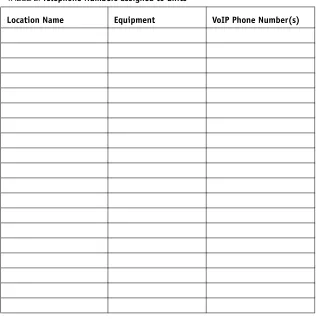
Use the following form to keep track of phone numbers assigned to units that are part of a TalkSwitch telephone network.
SIP server location:___________________________________________________ Equipment at SIP server location:_______________________________________ VoIP Phone Numbers assigned to SIP server location:_______________________
TABLE 2. Telephone Numbers assigned to units
APPENDIX B – VIEW REGISTRAR ENTRIES WINDOW EXAMPLE
The following is an example of the View Registrar Entries window, where each entry is comprised of the following fields:•
Client is the phone number assigned to a VoIP line.•
Contact is the information used by the SIP server to contact the client. It is comprised of the phone number, public IP address, and signalling port.•
Expires is the amount of time, in seconds, that the client is registered with the SIP server before having to re-register.APPENDIX C – VIEW REGISTRATION STATUS WINDOW EXAMPLE
The following is an example of the View Registration Status window, where each entry is comprised of the following fields:•
Client is the phone number assigned to a VoIP line.DOCUMENTATION FEEDBACK FORM
TalkSwitch appreciates your feedback and strives to continually improve and provide you with quality documentation.
Customer information (optional)
Comments Please provide your comments on this document’s ease-of-use and helpfulness, as well as any other comments in the space below.
How to Submit this form? You can submit this form using one of the following methods:
• Email your comments to [email protected]
• Fax this form to the Documentation department at 613.725.2989 • Mail form to TalkSwitch, Attention: Documentation,
1545 Carling Avenue, Suite 510, Ottawa, Ontario Canada, K1Z 8P9