An Experimental Study on Operating Parameter on Counter
flow Vortex Tube
A.S. GadhaveP
1
P
, Dr. S. S. KoreP
2
P.G. Student, Department of Mechanical Engineering, G.S. Moze COE, Balewadi, PuneP
1
Professor, Department of Mechanical Engineering, Sinhgad Institute of Technology, kondwa, PuneP
2
Abstract
The vortex tube (also called the Ranque–Hilsch vortex tube) is a mechanical device operating as a refrigerating machine without any moving parts, by separating a compressed gas stream into two low pressure stream, the temperature of which are respectively higher and lower than inlet stream. Such a separation of the flow into regions of low and high total temperature is referred to as the temperature (or energy) separation effect. The vortex tube performance depends on two types of parameters, firstly air or working parameters such as inlet pressure of compressed air, cold mass fraction and secondly tube or geometric parameters such as length of hot side tube, cold orifice diameter, number of nozzles, diameter of nozzle, cone valve angle and also material of vortex tube affects Coefficient of Performance (COP). This paper discusses the experimental investigation of effect of above working parameters on the performance of Ranque-Hilsch vortex tube. The brass material has been used for manufacturing of the vortex tube as it has better thermal conductivity and less fluid friction losses. In this experimental study the performance of vortex tube has been tested with compressed air at various pressures from 2-8 bar, which supplied through single tangential inlet nozzles. The L/D ratio of hot side tube varies 12.5 , 13.5 and 17.5 and cold mass fraction varied from 0 – 1.
Keywords:Energy separation process, COP, Ranque-Hilsch vortex tube.
1. Introduction
Oneofthe
practicalapplicationsofthermodynamicsisrefrigerati onwhereheatistransferredfrom lowtemperature regiontohightemperature regionthroughtheworking fluidknownas refrigerant.Vapour compressionandvapourabsorptionrefrigerationsyste msare two commonly employedconventionalsystemsinalmostallthemajora pplicationsof refrigeration and air-conditioning. However,environmental problems such as ozone
depletionandglobal warming
causedduetoCFCrefrigerantshavecompelledustoloo kfor other non-conventionalsystems.Vortextube is one ofthe non-conventionalsystemswhere natural substancesuch asair is used as workingmedium to achieverefrigeration.
The vortex tube (also called the Ranque–Hilsch vortex tube) is a mechanical device operating as a refrigerating machine without any moving parts, by separating a compressed gas stream into two low pressure stream, the temperature of which are respectively higher and lower than inlet stream. Such a separation of the flow into regions of low and high total temperature is referred to as the temperature (or energy) separation effect.
Much earlier, the great nineteenth century physicist James Clerk Maxwell, postulated that since heat involves the movement of molecules, we might someday be able to get hot and cold air from the same device with the help of a “friendly little demon” who will sort out and separate the hot and cold molecules of air. The vortex tube was invented by accident in 1928 by George Ranque, a French metallurgist as well as physicist, who were experimenting with a vortex type pump; he had developed; when he noticed warm air exhausting from one end and cold air from other. Ranque started a small firm to exploit the commercial potential of this strange device that produced hot and cold air without moving any parts. Ranque was granted a French patent for this device in 1932 and a United States patent in 1934P
[1, 2]
P
.
The initial reaction of the scientific and engineering communities to his invention was disbelief and
apathy. Since the vortex tube was
thermodynamically highly inefficient, it was abandoned for several years. Vortex tube slipped into obscurity until 1945; when a German physicist and engineer, Hilsch reported on account of his own comprehensive experimental and theoretical studies aimed at improving the efficiency of the vortex tube. He systematically examined the effect of the inlet pressure and the geometrical parameters of the vortex tube on its performance and presented a possible explanation of the energy separation process P
[4]
P
.
Since vortex flow phenomenon taking place in a vortex tube is compressible and complex, the simulation and solution of turbulent vortex flows is a difficult and challenging task. Thus, the vortex tube has been variously known as the “Ranque vortex tube”, the “Hilsch Tube”, the
Hilsch Tube” and “Maxwell’s Demon”. By any name, it has in recent past gained acceptance as a simple, reliable and low cost answer to a wide variety of industrial spot cooling problems.
2. Problem Statement
An experimental study has been conducted to evaluate the effect of working parameters such as inlet air pressure (PRiR), Cold mass fraction (μ) and
length of hot side tube (LRhR) on the performance of
Ranque-Hilsch vortex tube. In this work, the counter flow vortex tube has been designed, manufactured and tested. Different parameters were evaluated like temperature reduction on cold side, temperature rise on hot side, refrigerating effect and isentropic efficiency. The performance of vortex tube has been tested with compressed air at various inlet pressures from 2-8 bar which supplied through single tangential inlet nozzles. The L/D ratio of hot side tube varies 12.5, 13.5 and 17.5 and cold mass fraction varied from 0 – 1.
3. Design and Constructional Details of
Vortex Tube
TakahamaP
[22]
P
has proposed the following correlations for optimized RHVT for larger temperaturedifference,given as;
𝐷𝑖𝑛 / D 0.2 ……… (i)
𝐷𝑐2 / N𝐷𝑖𝑛2 ≤ 2.3 ……... (ii)
𝐷𝑐 D 2 𝐷𝑖𝑛 ………… (iii)
Considering all design parameters, the three different diameters of tubes are chosen at constant length as,D = 10mm, 13mm, 14mm and L/D = 12.5, 13.5, 17.5
D = 10 mm
Using Equation (i) 𝐷𝑛 D 0.2
𝐷𝑛 10 0.2
∴ 𝐷𝑛 2 mm
Diameter of inlet nozzle, 𝐷𝑛 = 2 mm Using Equation (ii)
𝐷𝑐2 2.3 N𝐷𝑛2
Considering N = 1 𝐷𝐶2 2.3 22 𝐷𝐶2 9.2
𝐷𝐶 3.03 mm
Diameter of cold end orifice, 𝐷𝑐= 3 mm
In order to find out the optimum dimensions for vortex tube three different L/D ratios i.e.
12.5,13.5, 17.5 are selected and also the cold orifice diameter are 3 mm, 4 mm and 5 mm are also selected.
Thegeometrical design parametersusedin the experimentationarelisted below in Table 1.
The counter-flow vortex tube consists of inlet nozzles, vortex chamber,separating cold orifice plate, hot side cone valve, hot and cold end
tubes.The Brass material has been used
formanufacturing of the vortex tube as it has better thermal conductivity,less fluid friction losses, easy to machining and moderete overallcost. A conical valve was provided on the right hand side of the tube toregulate the flow.
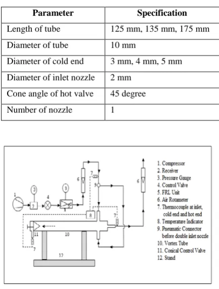
Table. 1 Detailed design Parameter
Parameter Specification
Length of tube 125 mm, 135 mm, 175 mm Diameter of tube 10 mm
Diameter of cold end 3 mm, 4 mm, 5 mm Diameter of inlet nozzle 2 mm
Cone angle of hot valve 45 degree Number of nozzle 1
Fig. 1 Schematic diagram of Experimental Setup
Theschematicdiagramoftheexperimentaltestfacility isshowninFig.1.Compressedair
fromthecompressor(1)passesthroughthecontrolvalv
e(4)andpressure regulatorfilter
section(5)andentersinthevortextube(10)tangentially.
Toensurethetangentially entry of
thecompressedairinthevortextubetohaveproperswirli ngoftheairspecialcarewas
taken.Thecompressedairexpandsinthe
vortextubeanddividesintocoldandhotstreams. The coldairleavesthecoldend
orificeneartheinletnozzlewhilethehotair dischargestheperiphery
atthefarendofthetubei.e.hotend(11).Thecontrolvalve
(needle valve) controlstheflowrateofthe hotair(11).Tworotameters (Eureka made)(6) measures the mass flow rates of the hot and cold air. Thermocouples numbered (7) measure the temperature of the leaving cold and hot air in the vortex tube. The pressure of inlet gas is measured by pressure gauge (2) and the temperature of inlet gas is measured by thermocouple (7). In order to uniformly divide the compressed air, a pneumatic connector is used which divide the incoming stream in to two separate streams and supplies to two nozzles of the vortex as shown in Fig. 2.
Fig.2 Photographs of experimentalsetup
Fig.3 Photograps of double inlet nozzle vortex tube
4. Result and Discussion
Experiments are performed under following conditions;
• Inlet pressures range : 2 bar – 8 bar • Cold mass fraction : 0 – 1
• L/D Ratio by varying diameter : 12.5,
13.5, 17.5
• Number of inlet nozzle : 1
• Working substance : Air
Effect of cold orifice diameterat L/D = 12.5: Experiment was performed on single inlet nozzle vortex tube, at various inlet pressures from 2 to 8 bars for three diameters of cold end orifice; 3 mm, 4 mm and 5 mm. For the first case of L/D = 12.5
Fig. 4 Effect of cold orifice diameter on cold end temperatures
at L/D = 12.5
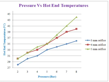
Fig. 5 Effect of cold orifice diameter on hot end temperatures at
L/D = 12.5
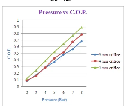
Fig. 6 Effect of cold orifice diameter on c.o.p. at L/D = 12.5
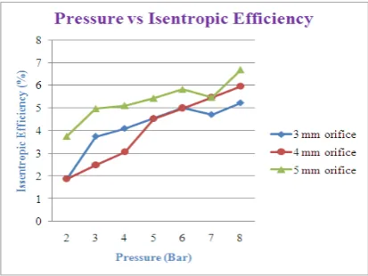
Fig. 7 Effect of cold orifice diameter on isentropic efficiency at
L/D = 12.5
Effect of cold orifice diameterat L/D = 13.5: Experiment was performed on single inlet nozzle vortex tube, at various inlet pressures from 2 to 8 bars for three diameters of cold end orifice; 3 mm, 4 mm and 5 mm. For the first case of L/D = 13.5
Fig. 8 Effect of cold orifice diameter on cold end temperature
at L/D = 13.5
Fig. 9 Effect of cold orifice diameter on hot end temperature at
L/D = 13.5
Fig. 10 Effect of cold orifice diameter on c.o.p. at L/D = 13.5
Fig. 11 Effect of cold orifice diameter on isentropic efficiency
at L/D = 13.5
Effect of cold orifice diameterat L/D = 17.5: Experiment was performed on single inlet nozzle vortex tube, at various inlet pressures from 2 to 8 bars for three diameters of cold end orifice; 3 mm, 4 mm and 5 mm. For the first case of L/D = 17.5
Fig. 12 Effect of cold orifice diameter on cold end temperature
at L/D = 17.5
Fig. 13 Effect of cold orifice diameter on hot end temperature
at L/D = 17.5
Fig. 14 Effect of cold orifice diameter on c.o.p. at L/D = 17.5
Fig. 15Effect of cold orifice diameter on isentropic efficiency
at L/D = 17.5
5. Conclusion
The following conclusions have been made from this experimentation:
1. The maximum temperature difference of 14°C is obtained on cold side while
17°C is obtained on hot side of Vortex tube.
2. The temperature drop increases with
increase in inlet pressure.
3. The maximum isentropic efficiency =
10.43% and C.O.P. = 1.12 obtained at 17.5 L/D ratio.
4. The optimum value of L/D ratio is 17.5 as in this ΔTc and ΔTh is maximum.
5. The highest temperature drop is found between 0.45-0.65 cold air mass fraction. 6. At 8 bar Inlet pressure, 17.5 L/D ratio and
0.65 Cold mass fraction give the best result.
References
[1] Ranque G.J., “Experiments on expansion in a vortex with simultaneous exhaust of hot air and cold air.” Le Journal De Physique, vol. 4, (1933), pp. 1125-1130. [2] Hilsch R., “The use of expansion of gases in a centrifugal field as a cooling process.” Review of Scientific Instruments, vol. 13, (1947), pp. 108-113. [3]Yilmaz M.,Kaya M.,Karagoz S.,Erdogan S., “ Areviewondesigncriteriaforvortex tubes.” Heat Mass Transfer, vol. 45, (2009), pp. 613–632.
[4] Promvonge P., Eiamsa-ard S., “Investigation on the Vortex Thermal Separation in a Vortex Tube Refrigerator.” Thailand.
[5] Xue Y.,Arjomandi,Kelso R., “Acriticalreview of temperature separationina vortex tube.” Experimental Thermal and Fluid Science, Vol34,(2010), pp. 1367-1374.
[6] Lewins J., Bejan A., “Vortextube optimization theory.” Energy, Vol.24, (1999), pp. 931–943.
[7] Deissler R.G., Perlmutter M., “Analysis of the flow and energy separation in a turbulent vortex.” International Journal of Heat Mass Transfer, Vol. 1, (1960), pp. 173–191.
[8]Eiamsa-ard S., Promvonge P., “Numericalpredictionofvortexflowand
thermalseparation
inasubsonicvortextube.”JournalofZhejiangUniversitySC IENCEA, V ol. 7(8), (2006), pp. 1406-1415.
[9] Takahama H., “Studies on vortex tubes.” Bull. JSME, Vol. 8 (31), (1965), pp. 433–440.