Abstract
HUGHES, ROBERT EUGENE. Analysis and Redesign of the Brim Forming Manufacturing Process (Under the guidance of Dr. M. K. Ramasubramanian)
The principles of mechatronic design have been further applied to develop a
robust brim curling system. The brim curling machine uses integration of mechanical,
electrical, and computing systems to form a unique machine that is able to produce
quality finished paperboard cups. This research involves the conversion from a PC controller to a stand-alone servo/stepper controller. The controller offers more
programming flexibility with improved process control. This research also explores
optimization of the brim curling machine to determine the maximum production rate.
The rotary and linear servo actuators were tuned using a PID scheme. The machine
processes for forming a brim were explored and time for the machine to complete these processes was evaluated. The process that took the most amount of time was the cup
shell feeding mechanism. The feeding mechanism was reconfigured and the time
required to feed a cup shell was reduced. Analysis was performed on a falling cup shell
to determine a theoretical time estimate. This research also investigates the effects of machine turret deflection and the deflection’s affect on cup brim thickness. Finite
element analysis was used to determine the stresses present in a redesigned coupling.
The coupling replaced a previously failed coupling. The brim curling machine was
completely reconfigured and the result is an industry ready high speed brim curling
Analysis and Redesign of the Brim Forming Manufacturing Process
by
Robert E. Hughes
A thesis submitted to the Graduate Faculty of
North Carolina State University
in partial fulfillment of the
requirements for the Degree of
Master of Science
Mechanical and Aerospace Engineering
Raleigh, North Carolina
August, 2003
APPROVED BY:
________________________ _________________________ Dr Gergory D. Buckner Dr. Stefan Seelecke (Advisory Committee Member) (Advisory Committee Member)
_________________________
Biography
I, Robert E. Hughes was born on August 29, 1974 in Burlington, North Carolina.
I was raised in rural Alamance County by my parents Dennis and Nancy Hughes. I graduated from Eastern Alamance High School in May of 1992. Upon graduation from
high school, I began my Bachelor’s degree in mechanical engineering at North Carolina
State University. In May of 1997, I completed my Bachelor’s degree with a minor in
graphic communications. I started work at Gardner Glass Products as a plant supervisor /
project engineer. In 1998, I moved to a maintenance / project engineer with Hendrix Batting in High Point.
I later decided I was interested in doing more design / prototype work. In order to
achieve this goal it was in my best interest to enroll in the Master’s program at North
Carolina State University. In the spring of 2001, I began working on my Master’s
degree. The first semester back in college I became interested in Mechatronics. I was intrigued by the thought of using a small microprocessor to control a machine or robot.
Subsequently, I decided to make Mechatronics my thesis concentration. I wanted to
work with machines and be able to make them semi- intelligent. Since working on my
degree, I have had the opportunity to be a teaching assistant to undergraduate mechanical
engineering students in manufacturing their senior design projects. I also gained further experience from this position which allowed me to design and create prototypes for
several design other projects.
After completion of my Master’s degree, I plan to continue working in the
mechatronics field designing and creating machine prototypes.
Table of Contents
List of Tables ... v
List of Figure s... vi
1. Introduction... 1
1.1 Mechatronics... 1
1.2 Drawbacks of Traditional Brim Curling Machines... 2
1.3 Prototype Brim Curling Machine... 2
1.4 Purpose... 4
2. Background ... 4
3. Mechatronic Design Considerations ... 5
3.1 Motion Control Software... 5
3.2 Machine Control and Program Flow... 6
4. Machine Performance... 9
4.1 Servo Control Variables... 9
4.2 Actuator Speeds and Machine Processes... 11
4.3 Cup Shell Feeding Mechanism ... 13
4.4 Improvements to increase production speeds... 17
5. Cup Shell Feeding Motion... 18
5.1 Free Falling Cup Shell... 18
5.2 Falling Cup Shell with Initial Velocity... 19
5.3 Effects of Drag Forces on the Cup Shell... 20
5.4 Theoretical Time Estimate to Feed One Cup & Actual Time Taken... 21
6. Finite Element Analysis of Machine Turret Plate & Turret Coupling ... 24
6.1 Analysis of Single Load Acting on Machine Turret without Cup Dies... 26
6.2 Analysis of Double Load Acting on Machine Turret without Cup Dies... 27
6.3 Analysis of Single Load Acting on Machine Turret with Cup Dies... 28
6.4 Analysis of Double Load Acting on Machine Turret with Cup Dies... 29
6.5 Effects of Machine Turret Deflection on Brim Thickness... 30
6.6 Solution to Prevent Machine Turret Plate Deflection... 33
6.7 Replacement of mechanical coupling... 34
7. Conclusions ... 39
7.1 Recommendations for Further Development... 40
8. References... 42
9. Appendices... 43
9.1 Operator’s Manual for Start-Up... 43
9.2 Compumotor 6K8 Onboard Programmable I/O’s and Function for Axes 1-4... 44
9.3 Compumotor 6K8 Drive Connector... 44
9.4 Radio Shack RS -232 Cable Pin Assignments... 45
9.5 Apex 40 Connections to 6K8 Drive Connector... 45
9.6 Apex 40 Connections to 6K8 Encoder Connector... 45
9.7 IDC B8001Connections to 6K8 Drive Connector... 46
9.8 IDC B8001 Connections to 6K8 Encoder Connector... 46
9.9 S Drive Connections to 6K8 Controller... 46
9.11 Compumotor 6K8 Output Functions for Axes 1-4... 47
9.12 Brim Curling Machine Assembly Drawing... 48
List of Tables
Table 6 -1 - List of Maximum Nodal Deflections Per Case ... 31
Table 9-1 - Onboard Programmable I/O’s ... 44
Table 9-2 – 6K8 Drive Connector... 44
Table 9-3 – RS-232 Cable Pin Outs... 45
Table 9-4 –Apex 40 Servo Drive Connections ... 45
Table 9-5 – Apex 40 Servo Drive Encoder Connections... 45
Table 9-6 – IDC B8001 Servo Drive Connections ... 46
Table 9-7 – IDC B8001 Servo Drive Encoder Connections ... 46
Table 9-8 – Parker S Drive Stepping Motor Connections ... 46
Table 9-9 - Triggered I/O Functions ... 47
List of Figures
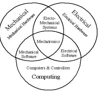
Figure 1.1 - Mechatronic Relationships ... 1
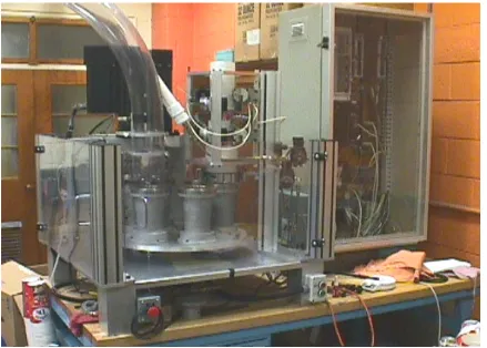
Figure 1.2 - Mechatronic Prototype Brim Curling Machine ... 3
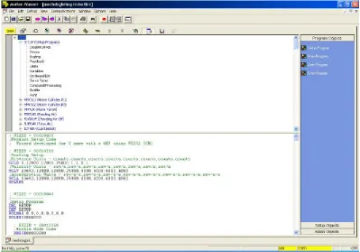
Figure 3.1 - Motion Planner Programming Software ... 6
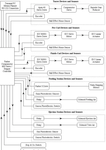
Figure 3.2 – Control Schematic of Brim Curling Machine ... 8
Figure 4.1 - Step Response of Turret Servo ... 10
Figure 4.2 – Step Response of IDC Linear Actuators ... 11
Figure 4.3 – Machine Processes to Manufacture a Cup Brim ... 12
Figure 4.4 - Cup Shell Feeding Mechanism ... 14
Figure 4.5 – Solid Model of Cup Shell Feeding Mechanism ... 16
Figure 5.1 - Free Body Diagram of Cup Shell ... 19
Figure 5.2 - Free Body Diagram of Cup Shell and Feed Wheels. ... 20
Figure 5.3 – Overall Free Body Diagram of Cup Shell ... 22
Figure 5.4 – Graphical Solution to Fourth Order Polynomial ... 23
Figure 6.1 – Solid Model of Machine Turret Plate ... 25
Figure 6.2 - Machine Turret Plate with Tetrahedral 4 Meshing ... 26
Figure 6.3 - Nodal Deflection of Machine Turret Plate with Single Load ... 27
Figure 6.4 - Nodal Deflection of Machine Turret Plate with Double Load... 28
Figure 6.5 - Nodal Deflection of Machine Turret Plate and Cup Holder for Single Load ... 29
Figure 6.6 - Nodal Deflection of Machine Turret Plate and Cup Holder for Double Load... 30
Figure 6.7 - Relationship between Angles of deflection... 32
Figure 6.8– Right Side Mounted Ball Transfer Rollers ... 33
Figure 6.9 - Center Mounted Ball Transfer Rollers ... 33
Figure 6.10 - Original Turret Plate Coupling... 35
Figure 6.11 - New Turret Plate Coupling ... 35
Figure 6.12 - Ansys® Stress Analysis Result for New Turret Coupling, Force Applied to Center Face of Coupling ... 37
Figure 6.13 - Ansys® Stress Analysis Re sult for New Turret Coupling, Force Applied to Outside Face of Coupling ... 38
1.
Introduction
In the past, industrial paper board machinery used to form drinking cup brims
consisted solely of mechanical systems. These machines were controlled from a central
main shaft. This main shaft provided the timing for all functions in the formation of paper cups. Branched off of this main shaft were other mechanical elements such as
gears, chains, and cams. Therefore all the machine functions were interdependent on one
another. As the main shaft spins, the cup shell is moved into the dies and rotated around
with each revolution. The main shaft also controls actuation of the brim curling dies that
form the cup brim. The finished cup is then indexed around and ejected from the machine.
1.1 Mechatronics
The term Mechatronics is used to denote a rapidly developing, interdisciplinary field of engineering that deals with the design of products whose function relies on the
synergistic integration of mechanical, electrical, and electronic components connected by
Mechatronic systems allow a designer to create not just a machine, but a system within
which machine can function. These machines are then able to make simple decisions on
their own without human intervention. This decision making process is due to the advancement in microprocessor based controllers. These controllers are stand alone
controllers that use analog and digital sensors provide input to make decisions, and use
electrical actuators to carry them out. Other advantages to mechatronic systems are; 1)
The systems require simplified mechanisms, 2) The systems are more compact, and 3)
The systems have higher accuracy due to feedback. Mechatronic products are used in a wide variety of products in today’s society. These products range from the automotive
industry to production of simple household products.
1.2 Drawbacks of Traditional Brim Curling Machines
Traditional brim forming machines have drawbacks due to its mechanical nature. Parts wear over time and cause timing inaccuracies and backlash. This will result in
changes in the quality of the products produced and eventually defective products. This
results in downtime for the machine and loss of production. Another drawback is the
inflexibility of the machine. To change form one product to the next involves complete
disassembly and reassembly resulting in weeks of downtime. Large number of custom parts and mechanisms make these machines very expensive to build, run, and maintain.
1.3 Prototype Brim Curling Machine
The prototype brim curling machine was developed at North Carolina State
coupled with a Parker Compumotor controller. The machine incorporates servo motors,
stepping motors, pneumatics, and other electrical components to form the cup brims. The
current machine is completely constructed from 6061 aluminum. The machine is composed of a feeding device, turret that has six cup holders, pre-curl station, final curl
station and ejection station. This machine uses a high torque servo and a high precision
gear reducer to index the turret. The turret indexes to the appropriate station each
function to be performed. Once the cup brim is formed the cup is finally indexed to the
ejection station.
1.4 Purpose
The purpose of this work is to develop a systematic analysis of the performance of the
machine. Identify bottlenecks, and improve performance through design changes. This evaluation involves the actual motion of the devices as well as program flow. Further,
critical components will be analyzed for stresses and redesigned if necessary to prevent
premature failure of mechanical components and improve reliability of the machine. The
ultimate goal of this research is to have a brim curling machine that is robust, intelligent
and performs optimally.
2.
Background
The prototype brim curling machine is a stand-alone system, instrumented to
obtain information in real-time. The machine has a rotary turret that holds six cup die
holders. This turret can be indexed precisely around to the various work stations. The
workstations include the feeding station, the pre-curl station, the final curl stage and the ejection stage. As the turret indexes, a cup shell is fed into the holder. The cup shell is
then indexed around until the final product is formed. The machine is continuous
production machine. Therefore, as one cup is indexed and formed, another cup is being
fed or waiting to be formed. The machine is controlled with a Parker AT6250 servo
controller [8]. This controller has four axis control capability. The machine uses a Compumotor rotary servo with a precision Bayside gear reducer to move the turret. The
pre-curl and finish curl dies are controlled by two IDC linear actuating servos. The
servos use rotary encoders to give position feedback. The servos use hall-effect sensors
actuators. The machine also has a cup shell feeding mechanism. This mechanism uses
stepping motors and pneumatics to feed the cup shells.
3.
Mechatronic Design Considerations
The prototype brim curling machine is an integration of mechanical and electrical components, driven by a central controller. The current prototype brim curling machine
was controlled by a PC based controller and control algorithm [2]. The installation of a
new controller to the prototype machine allows for greater control and more
functionality. The controller selected was a Parker 6K8 Controller [8]. The 6K8 is an
eight axis stepper/servo controller with a servo update rate of 62.5µs. The 6K8 controller
allows the total machine to be controlled and monitored from one source. This controller
is a stand-alone controller. That is, once the program is loaded there is no need of an
external PC.
3.1 Motion Control Software
Programs for the 6K controller were written using the Windows-based
programming tool Motion Planner (Figure 3.1). Motion Planner uses Compumotor’s
6000 motion control language for programming. This programming language uses
ASCII mnemonic commands followed by a command delimiter to provide signals to the
controller. As the controller receives commands, the commands are placed in an internal
buffer. From the buffer the commands are executed in the order upon which they are
received. The programs are downloaded to the controller using a RS-232 interface. The
the operating system and program are not lost. Once the program is downloaded the PC
is just used as a terminal to answer feedback questions or to receive machine feedback.
The 6K software has commands to allow a programmer to scale units for motion, home actuators, enable outputs, read digital and analog inputs, perform calculations,
multitask, and send feedback to external interface. This gives a system tremendous
flexibility to perform a multitude of operations. The system is also expandable for future
work.
Figure 3.1 - Motion Planner Programming Software
3.2 Machine Control and Program Flow
The 6K8 controller provides a solid platform for superior motion control. The controller enabled the brim curling machine to make precise movement to produce a
these axes control the appropriate servos while the other controls the feeder stepping
motors.
Once the controller was installed, the appropriate connections to the servo and stepper drives were made. The controller uses an -10 to +10 volt analog signal to control
the servos as well as the step and direction signal used to drive the steppers. In return, the
controller receives feedback from the encoders on the servos for motion control.
The controller has eight programmable outputs and seventeen programmable
triggered inputs. The brim curling machine utilizes three of the outputs and five inputs. The outputs control the pneumatics and the inputs are optical sensors to detect cup
positions for feeding and ejection.
The 6K8 also has a bank of limit inputs for each servo motor. These inputs are
used to give the system feedback such as home position, positive end of travel limit, and
negative end of travel limit. The home inputs were used for the turret servo and for both die actuators.
With the integration of the actuators, pneumatics, sensors, mechanics, and the
4.
Machine Performance
In order to have the machine perform optimally the servos need to be tuned for stable,
agile performance. This was done by determining the PID constants by a tuning
procedure. The proportional gain (P) was adjusted first to control peak overshoot. Next, derivative gain (D) was added to control settling time while the integral gain (I) was set
to control steady state error. Once the indexing servo was tuned optimally, the next step
was to tune the actuator servos for optimal performance. The next step was to study the
actuator speeds to determine the maximum production rate. Finally, the cup feeding
mechanism was critically reviewed, modeled, and improved.
4.1 Servo Control Variables
Initially, the servos were tuned using the Parker controller. Since the servos are
closed loop systems, each servo must be configured for optimum performance. After launching the servo tuner software, a first order response can be obtained. The servos on
the machine were tuned to a step function. This step is respectively a small step; only
2000 thousand counts on the encoders. The indexer encoder had a resolution of 4096
counts per revolution, and the actuator encoders were 8000 counts per revolution. The
encoder then provides feedback to the screen allowing the response to be viewed. The servo is then tuned by systematically adjusting the PID gains as described earlier.
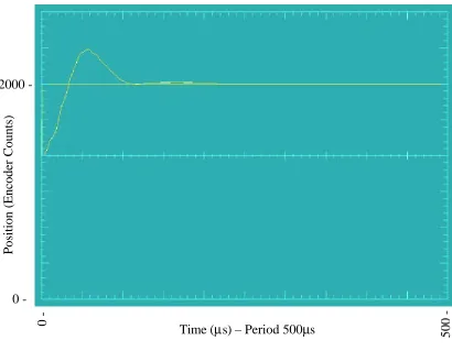
The turret is driven by a Compumotor Servo. The first order step response is
shown in Figure 4.1. The tuning gains are: P = 10, I = 20, and D = 15. Tuning the turret
servo proved to difficult. This was due to the small amount of backlash present in the
0 -
0
-
500
-
Figure 4.1 - Step Response of Turret Servo
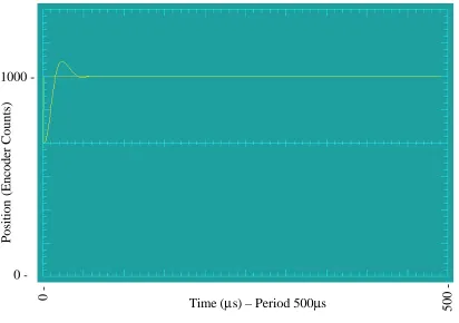
The pre-curl die and finish curl die are actuated by the IDC linear servo. Both
dies are actuated by the same type servo motor and both motors were tuned with the same
PID parameters. The first order response of the linear actuator is shown in Figure 4.2.
The tuning gains are: P = 8, I = 2, and D = 5.2. The gains gave a response that would
rise quickly and then settle to the desired value. It was desirable not to have a lot of
overshoot for these actuators so that when the actuator is programmed to move one inch,
there is only a few thousands variance from the mark. Time (µs) – Period 500µs
Position (Encoder Counts)
0 -
0
-
500
-
Figure 4.2 – Step Response of IDC Linear Actuators
4.2 Actuator Speeds and Machine Processes
Production rate is defined as the speed at which quality finished cups can be
produced. In the earlier design [2], the turret indexing speed was used as the production
speed which is incorrect. The brim curling machine production speed is based on cups per minute. The machine processes that the machine must perform to make one cup
include (Figure 4.3);
1.) Feeding the Cup 2.) Index 60o to Open Slot 3.) Index 60o to Pre-Curl Station 4.) Pre-Curl Actuation
5.) Index 60o to Finish-Curl Station 6.) Finish Curl Actuation
7.) Index 60o to Ejection Station
8.) Finished Cup Ejection from the Machine
Time (µs) – Period 500µs
Position (Encoder
Counts)
Figure 4.3 – Machine Processes to Manufacture a Cup Brim
In a manufacturing cycle, some of these processes happen simultaneously. Once the
program is started and the brim curling machine is in full operation, the production rate is
determined from the time the machine can feed a cup shell and index once. The other processes still occur but they are not a limiting factor in determining production rate.
Experiments were performed to determine the machine’s maximum production rate.
The first test was to determine the maximum production speed without any
feeding operation. The result will give a time value in milliseconds for the turret to index
60o and the linear actuator to move down and back to the home position. For this experiment a separate motion program was written to test the time value for this process.
In the motion program, the distance, velocity, and acceleration of the actuators are based
on the scaled values assigned in the program. For example, the scaled velocit y has the
units of counts/sec. The linear actuator has a maximum velocity of 20in/s and the turret
actuator with gear reducer has a maximum velocity of 112.5 rpm. The minimum time to Cup
Shell
Cup Shell Fed
Index 60o
Index 60o Pre-Curl Actuation
Index 60o Finish Curl Actuation Index 60o
Ejection Finished
complete this process was 0.45s. This yields a maximum production rate 133 cups per
minute.
The final experiment to determine the production rate used the same motion program with the feeding operation included. Using the velocities and accelerations from
the previous experiment, the time increased to 0.722s. This yields a maximum
production rate of 80 cups per minute. Therefore, it can be concluded that the cup
feeding mechanism is the rate limiting step in this process.
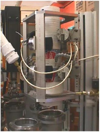
4.3 Cup Shell Feeding Mechanism
Cup shell feeding is an important issue in the production speed of this industrial
brim curling machine. A 32oz cup is difficult to feed because of the cups’ geometrical
shape and the effective stiffness of the cup shell. The cup shell must be fed in the proper
orientation and in the shortest amount of time possible. The mass of a 32oz cup shell is 0.0375lb. The feeding mechanism (Figure 4.4) uses eight stepping motors that are
driven by a Parker S-series stepping drive. These motors have foam rubber wheels
attached to the output shaft providing a friction hold on the cups until feeding is
necessary. Compressed air is used to help force the cup down into the holder as the
feeding wheels advance. The compressed air is controlled by a solenoid valve. The air is moved through four nozzles that are placed around the cup stack. The cup shells are
placed into the feeder in a stack. The advancement of the cup stack is controlled by a
series of three photoelectric sensors that detect when a cup needs to be fed. These
sensors also do error checking for proper feeding. When a cup shell needs to be fed, the
cup shells advance the air pressure blows the cup down through the guide tube and into
the cup holder. Photoelectric sensors also control when the steppers and air need to turn
off. The machine will remain at the feeding station until the sensors allow the cup shell to index to the forming station.
Figure 4.4 - Cup Shell Feeding Mechanism
Initially, the cup shell mechanism was very inconsistent in feeding the shells.
independent unit. Coordination with the rest of the machine was not robust, causing
inconsistency. Converting to the Parker S-drive allowed for more robust control due to
documentation available, and the ability to integrate into central controller. The S-drive was compatible with the 6K8 controller, which enabled the drives output to the stepping
motors to be scaled and worked seamlessly. This allowed for precise speed control and
for faster update rates to turn the stepping motors off and on. Due to the difficulty in
feeding a cup shell, it was determined that a slower velocity profile for the steppers was
far more beneficial than a fast velocity profile. Since the steppers move at 3.35in/s, the air pressure from the nozzles had the biggest affect in properly feeding the cup shells in
the shortest amount of time.
Another problem with the cup feeding process is feeding errors. Feeding errors
include; 1.) Double feeding cup shells 2.) Partially feeding cup shells 3.) Cup shells
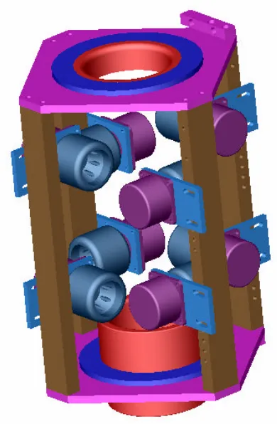
hanging between the feeder and the cup holder. These errors require operator intervention to be corrected. As shown in Figure 4.4, the stepping motors can be shifted
up or down along the vertical columns. Originally, the spacing of these motor was 9in
this allowing the cup shell stack to twist. The upper set of stepping motors were moved
together to reduce the spacing. Two of the stepping motors were positioned 6.5in apart
while the other two stepping motors were positioned 5.5in apart (Figure 4.5). This change gives the cup shell stack in the feeder more stability. The stepping motors can be
adjusted to increase or decrease the tension on the cup shell. The lower set of stepping
motors were positioned to have less pressure on the cup shell while the upper set was
stack to be held by the upper set of feeding wheels. This corrected a large percentage of
the feeding errors along with the determination of stepper motor velocity.
The biggest error that still plagued the feeding mechanism was the cup hanging between the feeder and the cup holder. This is a problem due to the distance between the
feeding mechanism and the cup holder. The cup had to travel a distance of 8in in the air
with no guidance. To solve this issue a feeding chute was installed in the bottom of the
feeding mechanism (Figure 4.5).
Figure 4.5 – Solid Model of Cup Shell Feeding Mechanism
This chute was made from a machinable plastic, Delrin. The inner diameter of the chute
was made 0.005in larger than the largest outer diameter of the cup shell. This provided
The effective distance the cup shell has to travel unguided with the feeding chute
installed is 1.75in.
Improvements to the feeding mechanism allow for optimum performance and consistency in feeding cup shells. Initially, the cup feeding mechanism could feed a cup
shell in approximately 350ms. After the modifications were complete and the velocity of
the stepping motors was set the feeding mechanism was capable of feeding a cup shell in
270ms. From the time the photoelectric sensors detect a cup shell, there is a 125ms time
delay to allow the cup to travel into the cup holder. If the cup shell does not clear these sensors in the allotted time, an error message is sent to the terminal for the operator to
check. Therefore, the cup shell must travel from the bottom of the cup stack into the cup
holder in 125ms. The other time required in feeding the cups is the result of the stepping
motors advancing the cup stack. The cup stack must advance approximately 0.4375in in
order for a cup to be released. Therefore, the time required for this advancement is 0.147s. These time values were determined experimentally with the use of internal
timers available in the 6K8 controller.
4.4 Improvements to increase production speeds
The brim curling machines is capable of producing up to 80 cups per minute. This production speed is not the maximum capability for the servos. In the optimization stage
there is a point where the machine becomes unstable. This instability is not due to poor
manufacturing of the machine, but partially due to the environment. The machine needs
a suitable base to be mounted upon. The table upon which the machine is placed moves
production speeds would be the addition of another set of brim curling stations. In order
to increase the production speed for the current brim curling machine the machine would
have to increase in size. Another feeding and ejection station would also have to be added. If the machine turret was larger in diameter then the machine speeds could
decrease as production speeds increase. Consequently, more cup holders could be
installed. This machine is very flexible and is capable of producing a high quality
product. This can be considered as an extension of this work.
5. Cup Shell Feeding Motion
The dynamics of feeding cup shells is important to the production rate of the brim
curling machine. The time the cup shell needs to leave the feeder and become seated in
the cup holder is important to the production speed of the machine. The following
analysis examines some the factors that affect the falling of the cup shell falling.
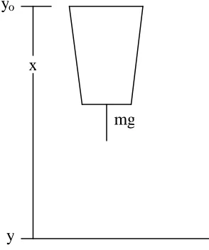
5.1 Free Falling Cup Shell
The first approach to finding the time taken for the cup to be fed was to consider a
freely falling cup (Figure 5.1). This analysis was done in order to get a baseline of how
long it took for a cup shell to travel from rest to the final destination. This base line time was done with the assumption that the forces of the surrounding air had no affect on the
time for the cup to drop. The distance the cup must travel is 8in. Also the cup is released
from rest. Therefore, the initial velocity of the cup shell is zero. In this analysis the only
force action on the cup is the force of gravity. Employing classical Newtonian mechanics
2 0
2 1
gt v
y
y− = o + (7.1)
In equation 7.1 (y) is the final distance and (yo) is the initial starting point. The
acceleration of gravity is denoted as (g), the time is give as (t), and (vo) is the initial
velocity. The time taken for the freely falling cup to reach its destination is 0.2035s.
Therefore for a cup shell to travel eight inches takes approximately 200ms. This is the
initial base line for determining how a cup shell can be fed.
Figure 5.1 - Free Body Diagram of Cup Shell
5.2 Falling Cup Shell with Initial Velocity
Now consider a falling cup shell with an initial velocity induced by the feeding
wheels (Figure 5.2). The velocity of the stepper motor was experimentally measured with a tachometer. The feed wheels have a constant velocity of 3.35in/s. The solution
yields a time value of 0.1950s. Therefore, the feeding wheels only drop approximately
50ms off the time to feed the cups versus a gravity feed. The speed of the feeding wheels
is very important. If the wheels index too far the feeder will double feed a cup shell. mg
x
Figure 5.2 - Free Body Diagram of Cup Shell and Feed Wheels.
5.3 Effects of Drag Forces on the Cup Shell
The component of the net force parallel to the uniform upstream flow is the drag
force [4]. This force acts on the moving cup shell and tries to slow it down. The drag
force, FD, is a function of the diameter, D, the fluid velocity, V, the density of the fluid, ρ,
and the viscosity, µ. The drag force can be represented in function form as:
) , , , (DV µ ρ f
FD = (7.2)
Using the Buckingham Pi theorem to evaluate the function the result is:
( )
Re2 f VD f A V FD = = µ ρ
ρ (7.3)
In equation 7.3 the cross-sectional area of the body is represented as (A). This equation is valid for incompressible flow of any body. Next, the drag coefficient is defined as:
From equation 7.3 and 7.4, the coefficient of drag can be shown as:
( )
Ref
CD = (7.5)
Since the coefficient of drag is a function of Reynolds number, the value for Reynolds number must be determined. If the value for Reynolds number is greater than 1000 the
drag coefficient will be independent of this value. For the cup shell, the Reynolds
number is around 8200. From Table 9.3 [4], the coefficient of drag for a disk is
approximately 1.15. This value is used to later determine the force of drag on the bottom
of the cup shell.
5.4 Theoretical Time Estimate to Feed One Cup & Actual Time Taken
To determine a theoretical time estimate to feed one cup shell all the forces acting
on the cup were considered and some assumptions made. The assumptions are:
• Neglect pressure build up inside the cup holder
• Drag Forces on the sidewalls of the cup shell are negligible
• Forces exerted by roller wheels is negligible compared to force of air nozzles
• Assume incompressible flow
• Assume viscous flow
• Neglect static pressure between the cups in the stack
Figure 5.3 shows the free body diagram of the cup shell. Consider Newton’s 2nd Law [5]:
( )
t x m ma FFigure 5.3 – Overall Free Body Diagram of Cup Shell
From Figure 5.3, all of the forces acting on the cup shell can be summed:
∑
F =Fair +Fgravity +Fwheels −Fdrag (7.6)Where Fair is a constant force exerted against the cup, Fgravity is equal to mg, Fwheels is
negligible and
A V C
FD D 2
2 1ρ
= (7.7)
The flow velocity is given by:
V =vo +gt (7.8)
The final result is:
( )
t F mg C(
v gt)
A xm air D o 2
..
2
1 +
− +
= ρ (7.9)
By integrating equation 7.9, displacement for the cup shell drop is a fourth order
polynomial in time.
Fgravity
Fwheels
Fdrag
Fair
x
( )
2 2 0 3 4 2 2 2 1 624 m t
Av C mg F t m g Av C t m Ag C t x D air o D D ρ ρ ρ − + + − − = (7.10)
Since x(t) is a constant, let a function G(t) be defined as:
( )
t xm Av C mg F t m g Av C t m Ag C t G D air o D D + − + − + = 2 2 0 3 4 2 2 2 1 6 24 ρ ρ ρ (7.11)
The positive root of function G(t) is the time required for a cup shell to be fed.
Numerical techniques, suc h as graphical simulations from Matlab, yields a required time
of 0.1071s for G(t) equal to 0 (Figure 5.4).
0 0.02 0.04 0.06 0.08 0.1 0.12 0.14 0.16
-0.2 -0.15 -0.1 -0.05 0 0.05 0.1 0.15 0.2 0.25 Time(seconds) G(t)
Theoretically, the time needed to feed one cup with the current system is 107ms.
Experimentally the time allowed for the system to feed a cup is 270ms. Due to the
difficulty in feeding cup shells, this is an acceptable time to feed one cup shell.
Another issue is pressure build up in the bottom of the cup holder as the cup
closes the cavity. This pressure build up can be overcome by pulling a vacuum on the
bottom of the cup holder. This will help overcome the drag force present on the cup
shell. The drawback to this idea is the cost of the extra compressed air used to create this
vacuum. Another way to reduce this pressure build up is to cut holes in the cup holders. This would allow the air to escape out the side of the cup holders. Another benefit of
these holes is a mass reduction of the cup ho lders and a decrease in rotational inertia
present on the turret plate.
6.
Finite Element Analysis of Machine Turret Plate & Turret
Coupling
Brim forming requires perfect alignment of curling iron and die for uniform brim
diameter. This is a critical attribute for snap lid assembly. If the turret plate deflects
downward then the die and iron will be nonparallel causing brim diameter variation. In order to understand the effect of turret plate deflection on die parallelism, finite element
analysis was used (Figure 6.1). This plate is constructed of ¾ in thick 6061 Aluminum.
The importance of analyzing this component is to determine if there is too much
deflection from the linear actuators creating quality issues in forming the cup as well as
environment in Unigraphics® was used to create a mesh and apply forces. The mesh
used was a triangulated mesh, Tetrahedral 4 (Figure 6.2) [6]. Boundary conditions were
assigned to rigidly hold the part in position. The points selected for the boundary conditions were where the machine turret bolts to the motor coupling. Force was applied
to the machine turret at the location where the cup die is mounted. After the mesh,
boundary conditions, and forces were applied, an Ansys® Structural file was created.
Ansys® was then used to solve the problem. The nodal solution was examined to
determine the maximum deflection of the plate.
Figure 6.2 - Machine Turret Plate with Tetrahedral 4 Meshing
6.1 Analysis of Single Load Acting on Machine Turret without Cup Dies
The first case considered was the machine turret plate with no cup dies attached
and a load of 400lb applied to one die hole. In this case, since the cup holder dies are not attached, the plate is more flexible and should have a higher deflection. After running the
Figure 6.3 - Nodal Deflection of Machine Turret Plate with Single Load
Nodal deflections from Figure 6.3 show a maximum deflection of 0.008244in at the tip of
the machine turret plate. The bar graph at the bottom of Figure 6.3 shows the deflection
distribution across the turret plate. The graph also shows the downward deflection to be
positive. That is a result of applying the force as 400lb in the negative direction. This
was done in order to show the deflection in the proper orientation.
6.2 Analysis of Double Load Acting on Machine Turret without Cup Dies
The second case considered was the machine turret plate with no cup dies
attached and a load of 400lb applied to two die holes. This case is a representation of two
As in the first case, there are no cup holder dies considered and this case should yield the
highest deflection. After running the Ansys® file, the nodal solution was determined.
Figure 6.4 - Nodal Deflection of Machine Turret Plate with Double Load
The nodal deflections from Figure 6.4 show a maximum deflection of 0.012623in at the tip of the turret plate. There was a increase of approximately 0.004in in deflection from
the extra load.
6.3 Analysis of Single Load Acting on Machine Turret with Cup Dies
The third case considered was the machine turret plate with the associated cup holders in position. For this case a single load of 400lb was applied to one cup holder.
For analysis purposes, the turret plate and the cup holder were modeled as one part. This
in essence, stiffened the turret plate. Therefore, the maximum nodal deflection should be
smaller than the first or second case.
Figure 6.5 - Nodal Deflection of Machine Turret Plate and Cup Holder for Single Load
The result of the nodal deflection analysis yielded a maximum deflection of 0.006471in
(Figure 6.5). This shows that the cup holder stiffens the turret plate however there is still
some noticeable deflection.
The final case considered double load acting on two cup holders. The load again
was 400lb applied to the top of each cup holder. This case would simulate the turret plate
deflection from a two stage brim forming process.
Figure 6.6 - Nodal Deflection of Machine Turret Plate and Cup Holder for Double Load
The resultant of the nodal deflection analysis for the double load yielded a maximum
deflection of 0.010139in (Figure 6.6). Even with the extra stiffness added by the cup
holder to the turret plate, there is only a difference reduction of 0.002in in deflection.
6.5 Effects of Machine Turret Deflection on Brim Thickness
Turret deflection will have effects on the brim thickness of the cup. The cup brim
drastically change the quality of the brim formed. Based on the finite element analysis
performed on the turret, there was noticeable amount of deflection (Table 6 -1).
Table 6 -1 - List of Maxi mum Nodal Deflections Per Case
Deflection Cases Maximum Nodal Deflection (in)
Turret Plate Single Load 0.008244
Turret Plate Double Load 0.012623
Turret Plate w\ Cup Holders Single Load 0.006471 Turret Plate w\ Cup Holders Double Load 0.010139
To show the percent change in brim thickness, the case for a single load on the machine
turret plate was used. A theoretical line was drawn from the center of the turret plate
through the center line of the cup holder position. Then, by using the nodal numbers
from Ansys®, the nodal deflections could be listed for each node corresponding to the
theoretical line drawn. The nodal values were then plotted and a best fit line could be
approximated. This, in turn, allowed for a good approximation of the turret plate
deflection along the vertical axis of the cup holder. This nodal deflection was calculated
to be 0.008in. Next, by assuming small angle approximation for the deflection, an angle
of tilt from the horizontal position could be determined. The angle theta (θ) calculated is
Figure 6.7 - Relationship between Angles of deflection
Figure 6.7 shows the relationship between the change in angle of the turret plate and the
top of the cup holder. This change in angle form the horizontal makes a 2% change in
brim thickness. The result is that the brims are formed with a thick and a thin side; a
change of approximately 0.003in.
One quality issue associated with the failure to produce a uniform brim could be
the inability for the lids to la tch properly onto the cup resulting in a recall of the product.
Another quality issue is that the brims may not curl properly causing a total loss of the
product being produced. A final quality issue is the change in brim thickness would
affect the effective stiffness of the cup brim. The turret deflection also created machine
hardware problems. This deflection will also cause misalignment of the dies and wear to
the brim forming dies. Furthermore, misalignment would cause premature failure of the
actuators from shock loads and induced side loading.
6.6 Solution to Prevent Machine Turret Plate Deflection
The solution to prevent turret plate deflections was the addition of six stud- mount
ball transfer rollers. These rollers were installed underneath the turret plate to help support the load induced from the brim curling operation (Figure 6.8 & Figure 6.9).
Figure 6.8– Right Side Mounted Ball Transfer Rollers
Figure 6.9 - Center Mounted Ball Transfer Rollers
The ball transfer rollers selected have a static load carrying capacity of 25lb each. The
composition of the main roller is nylon selected so that there would be minimal amount
rollers exert a reaction force on the outer edge of the turret plate to prevent unwanted
turret plate deflection. As a result, a tight uniform brim is formed.
6.7 Replacement of mechanical coupling
In order to improve the reliability of the machine further, another component that
was analyzed, namely the, mechanical coupling between the turret plate and the main
servo gear reducer. The original coupling was composed of 6061 Aluminum. This
coupling was designed to slide just over the shaft and be set screwed down to the shaft (Figure 6.10). This coupling caused machine alignment issues. This was a result from
the indexing load to which the machine turret is subjected. The turret plate indexes 60
degrees to the next position. In order to achieve this, the main servo must accelerate and
decelerate quickly. This operation at maximum production rate happens in about 400ms,
at a peak torque rate of 3,485 in- lbs. This shock load requires the old coupling to carry high loads on the key way. Over time, 3 years of intermittent operation, the key way
expanded and introduced unacceptable levels of play into the system. This play caused
die misalignment and defective brims.
Figure 6.10 - Original Turret Plate Coupling
To solve this problem a new coupling was designed (Figure 6.11). This coupling
is made of steel. The coupling was designed as a split coupling. Therefore the tolerances
for the shaft were tighter. The coupling was designed not only to allow the key to carry the load, but also to allow the surface area of the shaft to carry the load due to friction
between the output shaft and the collar. The split in the coupling allowed for ease in
assembly. Figure 6.11 shows another split collar that is installed on the outside of the
coupling. This collar allows the coupling to grip the gear reducer and prevent any
slippage.
Ansys® was also used to check the stresses in the new coupling. This analysis
was performed excluding the outer coupling. The analysis was first performed
considering the maximum torque of the servo. The force was first applied to the inside
face of the coupling while the turret bolt holes were fixed. The value for the force
applied to this face was distributed load of 5000lb. This gave a simulation as if the turret plate was stalled. Figure 6.12 shows the Von Mises stresses present in the coupling for
this case. The bar graph on the bottom of Figure 6.12 gives a stress range from
approximately 7psi to 2400psi for this case. The high stress region is located at the
Figure 6.12 – Von Mises Stresses on the New Coupling, Force Applied to Center Face of Coupling
In the next analysis, the center of the coupling was fixed. The force was then applied to the outer surface of the coupling.
Figure 6.13 shows the von Mises stresses present in the coupling for this case. The highest area of stress is located at the key way. The bar graph at the bottom of
Figure 6.13 – Von Mises Stresses on New Coupling, Force Applied to Outside Face of Coupling
Both cases show that the stresses are low for the new coupling. The yield stress
for machine steel is 50 to 100ksi [7]. The values of stress for the new coupling are much
smaller than the minimum value for yield. Therefore, the component is safe. These
stresses will be even lower with the addition of the split collar attached to the coupling.
The result is a well-designed coupling that will not add any external backlash to the
7.
Conclusions
Installation of the new controller and optimization of the cup forming processes has
shown that the brim curling machine is a robust mechatronic system. The performance of the machine is not based on the timing of mechanical systems working together, as in
traditional systems. The machine can be reconfigured by changing the variables and
sequences in the source code, without hardware changes. The machine shows intelligent
behavior by performing error checking to prevent loss of product or damage to the
machine itself. The installation of the 6K8 stand alone controller improved the system’s efficiency through faster processing speeds and gave the programmer multiple options to
create the motion program. The 6K8 controller provided a more reliable servo tuning
software.
The machine can produce up to 80 cups per minute. The machine is able to feed a
cup shell and form a brim in 722ms. The turret actuator is capable of indexing to the next station in 450ms with the balance of time used to feed the cup shell. The feeding
mechanism is capable of consistently feeding cup shells without errors.
Theoretical work shows that feeding a cup shell is a complex problem. There are a
number of factors that affect the falling of a cup shell. These factors limit the time a cup
shell can fall. To help speed up this process, air nozzles were used to force the cup shell down into the cup holder. It was determined that a cup shell could be fed in 107ms.
Work was also done to determine the influence of turret plate deflection on the
thickness of the brims. Finite element analysis showed that a 400lb load applied to the
To resolve this problem, ball transfer rollers were placed under the turret plate to resist
the load exerted during the brim forming process.
A redesign of the machine turret coupling allowed the machine to perform at high speeds. This coupling was analyzed by applying a 5000lb load to the outer and inner
faces of the coupling, using a finite element model. The tests show that the maximum
stress was well below the yield stress of steel. The coupling performed well under
production conditions with reduced backlash.
7.1 Recommendations for Further Development
The following list provides suggestions for additional research and product development.
1.) Add a pressure sensor to the forming dies. This sensor would be capable of sensing
the forming pressure inside of the cup. This would allow the cups to be quality tested
before the cups exited the machine, eg. Leak detection on every cup.
2.) Increase the size of the machine. This development will allow the machine to have
more forming and feeding stations. The result will be an increase in the production
rate.
3.) Make additions to the machine to complete the cup forming process. Create the cup
sealing and bottom forming apparatus. This will make the machine a complete unit. The machine will be able to take a sheet of paperboard, cut the cup shape, and form a
completed cup.
4.) Make uses of the controller’s ability to connect via the Ethernet. This will allow
machine. Therefore, a number of brim curling machines could be monitored and run
by one person in a work cell.
5.) Design and manufacture components to show that the machine can change production runs in a matter of minutes. Create a feeding mechanism that is capable of feeding
any size cup from 8oz to 32oz. This will decrease changeover time and allow the
machine to become more flexible. Produce turret plates that can be changed out to
allow for production of sma ller sized cups. Also, produce the associated dies to
complete this process and design a quick coupling to rigidly hold the dies in place after changeover is complete.
8.
References
[1] Histand, Micheal B. and Alciatore, David G. Introduction to Mechatronics and Measurement Systems McGraw Hill 1999.
[2] Swecker, Matthew Donald “Design of Mechatronic Device for High-Speed, Automated Brim Curling of Paper Containers,” M.S. Thesis, North Carolina State University, 1996.
[3] Serway, Raymond A. Physics For Scientists & Engineers. 3rd ed. Saunders College Publishing 1992.
[4] Fox, Robert W. and McDonald, Alan T. Introduction to Fluid Mechanics. John Wiley & Sons, Inc. 1992.
[5] Beer, Ferdinand P. and Johnston, Russell E. Jr. Vector Mechanics for Engineers.
5th ed. McGraw Hill 1988.
[6] Cook, Robert D., Malkus, David S. and Plesha, Michael A. Concepts and Applications of Finite Element Analysis. John Wiley & Sons, Inc. 1989.
[7] Gere, James M. and Timoshenko, Stephen P. Mechanics of Material. 3rd ed. PWS Publishing Company, Boston 1984.
9.
Appendices
9.1 Operator’s Manual for Start-Up
Start -Up Procedure for Terminal / Programming PC
1. Turn on the terminal PC.
2. Open Motion Planner Software Program
3. Motion Planner asks for Default Communications. Press OK. 4. Open motion program.
5. If motion program is not already stored in 6K8 then the file can be downloaded. Motion Program cannot be downloaded until the machine is powered.
6. Open terminal Screen
7. To start program type “SETUP”
8. The appropriate axes should initialize, then type in “MAIN”
9. Follow instructions given by motion program on the terminal screen.
Start – Up Procedure for Brim Curling Machine
1. Attach compressed air line to quick coupling on the wall. Air will flow from the machine until the machine is powered and SETUP from the PC has been run. 2. Check building pressure to ensure the pressure is at least 80psi.
3. Before powering machine, check pre-curl and finish curl actuators to make sure that they are not in any interference with the turret. “This is a machine safety precaution.” If the actuators need to be adjusted then set them just above the top of the cup holders.
4. Turn on the 230V 3-phase power disconnect. 5. Turn on the 120V single phase power.
6. At this point the PC and Motion Planner are running, and the program can be downloaded or run.
9.2 Compumotor 6K8 Onboard Programmable I/O’s and Function for Axes 1-4
Table 9-1 - Onboard Programmable I/O’s
6K8 Control Function Bit # Pin #
Function for Brim Curling Machine
Positive End of Travel Limit, Axis 1 1 23 Not Used Negative End of Travel Limit, Axis 1 2 21 Not Used
Home Limit, Axis 4 3 19 Home Switch for Turret Actuator
Positive End of Travel Limit, Axis 2 4 17 Not Used Negative End of Travel Limit, Axis 2 5 15 Not Used
Home Limit, Axis 4 6 13 Home Switch for Linear Actuator
Positive End of Travel Limit, Axis 3 7 11 Not Used Negative End of Travel Limit, Axis 2 8 9 Not Used
Home Limit, Axis 4 9 7 Home Switch for Linear Actuator
Positive End of Travel Limit, Axis 4 10 5 Not Used Negative End of Travel Limit, Axis 4 11 3 Not Used
Home Limit, Axis 4 12 1 Not Used
Note: All even pin #’s correspond to earth ground (GND)
9.3 Compumotor 6K8 Drive Connector
Table 9-2 – 6K8 Drive Connector
Pin # Wire Color Function
7 Brown Shtno
14 Yellow Common
8 Grey Shtnc
3 Black CMD+
6 Red CMD-
5 Green DRF
13 White Iso GND
15 Blue AGND
-- Orange No Connection
-- Purple Outside Jacket – No Connection
9.4Radio Shack RS -232 Cable Pin Assignments
Table 9-3 – RS-232 Cable Pin Outs
Pin # Wire Color
1 Black
2 Brown
3 Red
4 Orange
5 Yellow
6 Green
7 Blue
8 Purple
9 Grey
9.5 Apex 40 Connections to 6K8 Drive Connector
Table 9-4 –Apex 40 Servo Drive Connections
Apex 40 Signal Name
Compumotor 6K8 Signal Name
Compumotor 6K8 Connector Pin #
Enable In SHTNO 7
Fault Out DFT 5
GND AGND 15
-- COM 14 *
Command + CMD + 3
Command - CMD - 6
* -- For this connection also jump COM pin to AGND
9.6Apex 40 Connections to 6K8 Encoder Connector
Table 9-5 – Apex 40 Servo Drive Encoder Connections
Apex 40 Signal Name Compumotor 6K8 Signal Name Compumotor 6K8 Connector Pin Radio Shack RS-232 Wire Color
CHA + A+ 2 Brown
CHA - A- 3 Red
CHB + B+ 4 Orange
CHB - B- 5 Yellow
CHZ + Z+ 6 Green
CHZ - Z- 7 Blue
GND GND 9 Grey
-- -- 1 No Connection
9.7IDC B8001Connections to 6K8 Drive Connector
Table 9-6 – IDC B8001 Servo Drive Connections
IDC B8001 Signal Name
Compumotor 6K8 Signal Name
Compumotor 6K8 Connector Pin #
Enable SHTNO 7
Fault DFT 5
Common AGND 15
-- COM 14 *
Command + CMD + 3
Command - CMD - 6
* -- For this connection also jump COM pin to AGND
9.8IDC B8001 Connections to 6K8 Encoder Connector
Table 9-7 – IDC B8001 Servo Drive Encoder Connections
IDC B8001 Signal Name Compumotor 6K8 Signal Name Compumotor 6K8 Connector Pin Radio Shack RS-232 Wire Color
CHA + A+ 2 Brown
CHA - A- 3 Red
CHB + B+ 4 Orange
CHB - B- 5 Yellow
CHZ + Z+ 6 Green
CHZ - Z- 7 Blue
GND GND 9 Grey
-- -- 1 No Connection
-- -- 8 No Connection
9.9S Drive Connections to 6K8 Controller
Table 9-8 – Parker S Drive Stepping Motor Connections
S-Drive Signal Name
Pin # Compumotor 6K8 Signal Name
Pin #
Step + 1 Step + 1
Step - 14 Step - 9
Direction + 2 Direction + 2
Direction - 15 Direction - 10
Shutdown + 16 Shutdown + 11
Shutdown - 17 Shutdown - 12
Fault Output 9 Drive Fault 5
9.10 Compumotor 6K8 Triggered I/O Functions for Axes 1-4
Table 9-9 - Triggered I/O Functions
Bit # Pin # Program Function Cup Brim Forming Machine Function
1 23 Triggered Input 1 (TRIG-1A) Sunx Photoelectric Feeding Sensor #1 2 21 Triggered Input 2 (TRIG-1B) Sunx Photoelectric Feeding Sensor #1 3 19 Triggered Input 3 (TRIG-2A) Sunx Photoelectric Feeding Sensor #1 4 17 Triggered Input 4 (TRIG-2B) Sunx Photoelectric Feeding Sensor #1
5 15 Triggered Input 5(TRIG-3A) --
6 13 Triggered Input 6 (TRIG-3B) Production GO Button 7 11 Triggered Input 7(TRIG-4A) Production STOP Button
8 9 Triggered Input 8 (TRIG-4B) Omron Photoelectric Tube Clear Sensor
Note: All even pin #’s correspond to earth ground (GND)
9.11 Compumotor 6K8 Output Functions for Axes 1-4
Table 9-10 – Output Functions
Bit # Pin # Program Function Cup Brim Forming Machine Function
1 7 Output 1 Ejection Air Solenoid
2 5 Output 2 Feeding Air Solenoid
3 3 Output 3 Tube Air Solenoid
4 1 Output 4 --
9.12 Brim Curling Machine Assembly Drawing
Figure 9.1 – Solid Model Representation of Brim Curling Machine
9.13 Cup Brim Forming Motion Program
Motion Program file for Brim Curling Machine Written by: Robert Hughes
Date: 4/20/03
;Product Setup Code
; Wizard developed for 8 axes with a 6K8 using RS232 COM1
;Scaling Setup
;Distance Units - counts,counts,counts,counts,counts,counts,counts,counts SCLD 1,12000,12000,25000,1,1,1,1
;Velocity Units - rev/s,rev/s,rev/s,rev/s,rev/s,rev/s,rev/s,rev/s SCLV 13653,12000,12000,25000,4000,4000,4000,4000
;Acceleration Units - rev/s/s,rev/s/s,rev/s/s,rev/s/s,rev/s/s,rev/s/s,rev/s/s,rev/s/s SCLA 13653,12000,12000,25000,4000,4000,4000,4000
;Setup Program DEL SETUP DEF SETUP
FOLMAS 0,0,0,0,0,0,0,0 FOLEN00000000
;Enable Mode Code DRIVE00000000 ;Drive Setup
;Axis 1, Servo Control, Apex Drive, TURRET ;Axis 2, Servo Control, Other Drive, CYLINDER#2 ;Axis 3, Servo Control, Other Drive, CYLINDER#1 ;Axis 4, Stepper Control, S Drive, FEEDSTEPPERS ;Axis 5, Servo Control, No Drive
;Axis 6, Servo Control, No Drive ;Axis 7, Servo Control, No Drive ;Axis 8, Servo Control, No Drive AXSDEF 11101111
DRFLVL 11111111 DRFEN 11110000 KDRIVE 111X0000 DRES ,,,25000,,,, PULSE ,,, 0.3,,,,
DSTALL XXX0XXXX
;Scaling Setup
;Because scaling commands are not allowed in a program, ;the scaling commands will be placed at the beginning ;of the program file. This insures that motion programs ;in subsequent programs will be scaled correctly.
;Feedback Setup SFB 1,1,1,,1,1,1,1 ERES 4096,8000,8000,,4000,4000,4000,4000 SMPER 4000,4000,4000,,4000,4000,4000,4000 EFAIL 000X0000 ENCPOL 000X0000 ENCSND 000X0000 ESTALL XXXXXXXX ESK XXXXXXXX ENCCNT XXXXXXXX ;Hardware Limit Setup LH 0,0,0,0,3,3,3,3
;Software Limit Setup LS 0,0,0,0,0,0,0,0 LSAD 100,100,100,100,100,100,100,100 LSADA 100,100,100,100,100,100,100,100 LSNEG 0,0,0,0,0,0,0,0 LSPOS 0,0,0,0,0,0,0,0
;Home Limit Setup
HOMA 10,10,10,10,10,10,10,10 HOMAA 10,10,10,10,10,10,10,10 HOMV 0.25,2,2,1,1,1,1,1 HOMAD 10,10,10,10,10,10,10,10 HOMADA 10,10,10,10,10,10,10,10 HOMBAC 11100000 HOMZ 000xxxxx HOMDF 100xxxxx HOMVF 0.1,1,1,0,0,0,0,0 HOMEDG 111xxxxx LIMLVL 000000000000000000000000 ;Variable Setup
VAR1 = 13653.00000000 ;FSVARR01 VAR2 = -40.00000000 ;FSVARR02 VAR4 = -13653.33300000 ;FSVARR04 VAR5 = 0.98750000 ;FSVARR05 VAR6 = 0.68750000 ;FSVARR06 VAR7 = 0.12500000 ;FSVARR07 VAR8 = 0.00000000 ;FSVARR08 VAR13 = 0.00000000 ;FSVARR13 VAR14 = 0.00000000 ;FSVARR14 VAR15 = 0.00000000 ;FSVARR15 VAR16 = 0.00000000 ;FSVARR16 VAR17 = 0.00000000 ;FSVARR17 VAR18 = 0.00000000 ;FSVARR18 VAR20 = 0.00000000 ;FSVARR20 VARI14 = 0 ;FSVARI14
VARI16 = 0 ;FSVARI16 VARI18 = 0 ;FSVARI18
VARS1 = "0" ;INPUT#OFCUPS VARS2 = "0" ;SPEEDOFMACHINE VARS3 = "0" ;ENDPRODUCTION VARS4 = "0" ;USERERRORINPUT
LIMFNC 1-1R ;Functions for hardware limit inputs, LIMFNC 2-1S ;Functions for hardware limit inputs, LIMFNC 3-1T ;Functions for hardware limit inputs, LIMFNC 4-2R ;Functions for hardware limit inputs, LIMFNC 5-2S ;Functions for hardware limit inputs, LIMFNC 6-2T ;Functions for hardware limit inputs, LIMFNC 7-3R ;Functions for hardware limit inputs, LIMFNC 8-3S ;Functions for hardware limit inputs, LIMFNC 9-3T ;Functions for hardware limit inputs, LIMFNC 10-4R ;Functions for hardware limit inputs, LIMFNC 11-4S ;Functions for hardware limit inputs, LIMFNC 12-4T ;Functions for hardware limit inputs, LIMFNC 13-5R ;Functions for hardware limit inputs, LIMFNC 14-5S ;Functions for hardware limit inputs, LIMFNC 15-5T ;Functions for hardware limit inputs, LIMFNC 16-6R ;Functions for hardware limit inputs, LIMFNC 17-6S ;Functions for hardware limit inputs, LIMFNC 18-6T ;Functions for hardware limit inputs, LIMFNC 19-7R ;Functions for hardware limit inputs, LIMFNC 20-7S ;Functions for hardware limit inputs, LIMFNC 21-7T ;Functions for hardware limit inputs, LIMFNC 22-8R ;Functions for hardware limit inputs, LIMFNC 23-8S ;Functions for hardware limit inputs, LIMFNC 24-8T ;Functions for hardware limit inputs,
LIMLVL 000000000000000000000000
;Onboard Triggers
INLVL 011010110000000000
;Onboard Outputs
OUTFNC 1-A ;Output function assignment, EJECTRELAY OUTFNC 2-A ;Output function assignment, FEEDRELAY OUTFNC 3-A ;Output function assignment, TUBERELAY OUTFNC 4-A ;Output function assignment,
OUTFNC 5-A ;Output function assignment, OUTFNC 6-A ;Output function assignment, OUTFNC 7-A ;Output function assignment, OUTFNC 8-A ;Output function assignment,
OUTLVL 11100000
;Servo Tuner Setup
SGP 10,8,8,,0.5,0.5,0.5,0.5 SGI 20,2,2,,0,0,0,0
SGILIM 75,50,50,,0,0,0,0 SGV 15,5.2,5.2,,0,0,0,0 SGVF 0,0,0,,0,0,0,0 SGAF 0,0,0,,0,0,0,0
;Command Processing Code
;Command Processing Dur ing Motion COMEXC 0
;Enable Mode Code DRIVE11110000 ;Native Code module
WRITE" SETUP COMPLETE"
;Error Setup
;To modify the error bits,
;Please double-click on your Error Program
; Error program setup
ERRORP CRASH ; Error program setup
ERROR XXXXXXXXXXXXXXXXXXXXXXXXXXXXXXXX ; Bits tested END
;--- ;User Program
;Subroutine to home cylinder one DEL HMCYL1
;Native Code module write"homing cylinder #1"
;Home Code HOM xx1xxxxx
;Set Position Code PSET ,,0,,,,, END
;--- ;User Program
;Subroutine to home cylinder 2 DEL HMCYL2
DEF HMCYL2
;Native Code module write"homing cylinder #2"
;Home Code HOM x1xxxxxx
;Set Position Code PSET ,0,,,,,, END
;--- ;User Program
;Subroutine to Home Turret DEL HMTUR
DEF HMTUR
;Native Code module write"homing turret"
;If Code
IF(LIM=bxxxxx1xx1) ;Home Code
HOM 0xxxxxxx
;Assignment Code
VAR3 = VAR1 +VAR2 ;
;Motion Parameter Code ;Distance
D (VAR3),,,,,,,
;Motion Parameter Code ;Velocity
V .25,,,,,,,
;Go Code GO 10000000
;Native Code module TPE
ELSE NIF END
;--- ;User Program
;Subroutine to cut on the feed air DEL FEEDAR
DEF FEEDAR
;Output Code OUT x1xxxxxx END
;--- ;User Program
;Subroutine to turn feeding air off DEL FDAROF
DEF FDAROF
;Output Code OUT x0xxxxxx END
;--- ;User Program
;Subroutine to turn on Tube air DEL TUBEAR
;Output Code OUT xx1xxxxx END
;--- ;User Program
;Subroutine to turn on air to eject cup DEL EJTAIR
DEF EJTAIR
;Output Code OUT 1xxxxxxx END
;--- ;User Program
;Subroutine to turn ejection airoff DEL EJTOFF
DEF EJTOFF
;Output Code OUT 0xxxxxxx END
;--- ;User Program
;Error subroutine to clear blocked ejection tube DEL CLRTBE
DEF CLRTBE
GOSUB AIROFF ;Native Code module
write"***** Error - Ejection Tube Blocked *****\13" write"*** Make Sure Tube is Clear at Collision End ***\13" write"**** Press GO Button to Blast Out and Resume ****\13"
;Wait Code
WAIT(IN=bxxxxx1) GOSUB EJTAIR GOSUB TUBEAR ;Wait Code
;If Code
IF(IN=bxxxxxxx1) ;Native Code module
write"****** Failure to Clear Tube -- Still Clogged *****\13" write"*** Shutting Down -- Manually Clear Tube and Restart ***\13"
GOSUB CRASH ELSE
NIF END
;--- ;User Program
;Subroutine for sunx 4 sensor at entrance of ejection tube DEL TUBEIN
DEF TUBEIN
;Native Code module TIMST0
;Loop Action REPEAT
;Assignment Code VARI9 = VARI9 +1 ;
;Native Code module IF (TIM>500)
write" Tube entrance blocked" write" ending production" write" Check air pressure"
CRASH
NIF
UNTIL(IN=bxxx0) END
;--- ;User Program
;Cut the freakin air off DEL AIROFF
DEF AIROFF