ABSTRACT
SHAO, YUTIAN. Behavior of FRP-Concrete Beam-Columns under Cyclic Loading. (Under the direction of Amir Mirmiran)
Use of concrete-filled fiber-reinforced polymers (FRP) tubes (CFFT) for columns and piles has been studied extensively over the last decade. The focus, however, has been exclusively on the monotonic behavior of CFFT. An issue that has received little attention is the implications of using CFFT in seismic regions. Survey of damaged structures in recent earthquakes indicates that catastrophic failure of an entire structure may result from failure of few columns in a chain action. Since it may not be economical to design columns to respond to earthquake loads in their elastic range, dissipation of energy by post-elastic deformation is desired. Although, FRP materials are known for their linear elastic behavior, some FRP systems may exhibit non-linearity due to their laminate architecture and inter-laminar shear. Also, confinement of concrete core in CFFT improves its ductility. This study was carried out to evaluate the cyclic behavior of CFFT beam-columns, and determine whether non-linearity of FRP or confinement of concrete can provide seismic performance comparable to reinforced concrete (RC) columns or concrete-filled steel tubes (CFST).
compression. A fiber element model was employed to predict the cyclic behavior of CFFT columns. A parametric study was carried out on the cyclic behavior of CFFT beam-columns, and to compare the hysteretic response of CFFT beam-columns with those of RC and CFST members.
BEHAVIOR OF FRP-CONCRETE
BEAM-COLUMNS UNDER CYCLIC LOADING
by
YUTIAN SHAO
A dissertation to the Graduate Faculty of North Carolina State University
in partial fulfillment of the requirements for the Degree of
Doctor of Philosophy
CIVIL ENGINEERING
Raleigh
2003
APPROVED BY:
_________________________ __________________________
BIOGRAPHY
Yutian Shao received his Bachelor of Engineering degree in Civil Engineering in 1992 from
Tsinghua University, Beijing, China, and his Master of Engineering degree in Structural
Engineering in 2000 from the National University of Singapore. He recently successfully
completed the pursuit of his doctoral degree form North Carolina State University in
Structural Engineering. From1992 to 1997, he worked as a structural engineer in Beijing
Urban Engineering Design and Research Institute. In 1999, he worked as a structural
engineer in T.Y.LIN (South East Asia) Pte. Ltd. His research interests are primarily in the
area of applications of Fiber Reinforced Polymer (FRP) composite material in structural
engineering. His research at North Carolina State University was under the supervision of Dr.
ACKNOWLEDGMENTS
I would like to express my profound gratitude to my advisor, Dr. Amir Mirmiran,
Professor of Structural Engineering, P.E. for his systematic guidance, enthusiastic support
and valuable suggestions throughout the entire research work. I would also like to thank Dr.
Sami Rizkalla, Dr. Mervyn Kowalsky and Dr. Eric Klang for their time and effects in
reviewing this dissertation and serving on the committee.
I am also grateful to the National Science Foundation (NSF) and the Florida
Department of Transportation (FDOT) for providing the research funding.
Special thanks are also due to the technical and management staff of the Constructed
Facilities Laboratory of the North Carolina State University, especially Mr. Jerry Atkinson,
Mr. William Dunleavy, Mr. Jeremy Bloom and Ms. Patricia Rollins for all their help with the
experimental work.
Finally, this dissertation is especially dedicated to my mother, my father and my wife
for their patient and faithful encouragement throughout the entire course of this work. I
would also like to thank all my friends and colleagues, Wenqing Yuan, Xiaobing Chen,
Wassim Naguib, Iftekhar Ahmad, Zhenyu Zhu and Zhenhua Wu for their encouragement and
TABLE OF CONTENTS
LIST OF TABLES………. viii
LIST OF FIGURES……….……….. x
CHAPTER 1 INTRODUCTION……… 1
1.1 Problem Statement…….……….. 1
1.2 Research Objectives………. 2
1.3 Research Approach………... 3
1.4 Organization of the Dissertation……….. 5
CHAPTER 2 LITERATURE REVIEW………. 6
2.1 Introduction………... 6
2.2 Confinement Models for Concrete……… 6
2.3 Cyclic Behavior of Plain and Confined Concrete………. 9
2.4 Modeling of FRP Laminates………. 10
2.5 Applications of CFFT Beam-Columns………..………... 15
2.6 Evaluation Criteria for Seismic Performance………... 17
2.6.1 Ductility………. 17
2.6.2 Stiffness Degradation………. 19
2.6.5 Damage Index……… 22
CHAPTER 3 EXPERIMENTAL WORK………... 32
3.1 Test Plan………..……...………... 32
3.2 Large-scale CFFT Beam-Column Tests ……….………. 33
3.2.1 Test Specimens………..……… 33
3.2.2 Specimen Fabrication….……… 36
3.2.3 Instrumentation……….. 37
3.2.4 Test Setup and Procedure………... 39
3.2.5 Test Observations and Failure Modes……… 41
3.2.6 Test Results and Discussions………. 42
3.3 FRP Confined Concrete Stub Tests………...………... 50
3.3.1 Test Specimens……. ……… 50
3.3.2 Specimen Fabrication….……… 51
3.3.3 Instrumentation……….. 52
3.3.4 Test Setup and Procedure………... 52
3.3.5 Test Observations and Failure Modes……… 53
3.3.6 Test Results and Discussions………. 54
3.4.2 Instrumentation Test Setup and Procedure……..……….. 57
3.4.3 Test Observations and Failure Modes……… 58
3.4.4 Test Results and Discussions………. 59
CHAPTER 4 MODELING OF FRP-CONCRETE BEAM-COLUMNS…………... 142
4.1 Introduction………... 142
4.2 Modeling for FRP-Confined Concrete in Uniaxial Compression………. 142
4.2.1 Monotonic Model….………. 142
4.2.2 Cyclic Model……….. 144
4.2.2.1 Unloading from Envelope Curve to Zero Stress………. 144
4.2.2.2 Reloading from Zero Stress to Envelope Curve………. 147
4.2.2.3 Unloading between Arbitrary Stress Levels…………..……. 148
4.2.2.4 Reloading between Arbitrary Stress Levels………...…. 148
4.2.2.5 Validation of the Cyclic Model………..…………. 149
4.3 Modeling of FRP Laminates………..………...…………..……….. 150
4.3.1 Modeling of White Tubes in Monotonic Loading………. 150
4.3.2 Modeling of White Tubes in Cyclic Loading……… 151
4.3.3 Modeling of Yellow Tubes in Monotonic Loading…………... 151
4.4.1 Validation for the Fiber Element Analysis Tool……… 157
CHAPTER 5 PARAMETRIC STUDIES AND COMPARISONS……… 177
5.1 Parameter Selection………... 177
5.2 Parameter Assessment…………...……… 179
5.2.1 Hysteretic Response………... 179
5.2.2 Envelope Curve..…………... 181
5.2.3 Cumulative Energy…………... 182
5.2.4 Ductility………... 182
5.2.5 Pinching…………... 183
5.3 Comparison between CFFT and RC Beam-Columns…………..…….… 184
CHAPTER 6 SUMMARY, CONCLUSIONS AND RECOMMENDATIONS….... 217
6.1 Summary….……….. 217
6.2 Conclusions………... 218
6.3 Recommendations for Further Research………...……… 220
REFERENCES……… 221
APPENDIX A Cyclic Stress-Strain Relation for Steel ……..……… A-1
LIST OF TABLES
2.1 Mechanical Properties of Typical Thermoset Resins………... 24
2.2 Damage Index Classifications………...………... 24
3.1 Test Matrix of FRP-Concrete Beam-Column Specimens………..……. 62
3.2 Mechanical Properties of White FRP Tubes……… 63
3.3 Mechanical Properties of Yellow FRP Tubes……….. 63
3.4 Comparison of White and Yellow Tubes………. 64
3.5 Technical Properties of Electrical Resistance Strain Gages………...…. 65
3.6 Matrix of FRP-Confined Stub Tests……… 66
3.7 Mechanical Properties of GFRP Laminates……..………….……….. 67
3.8 Mechanical Properties of CFRP Laminates………...……….. 67
3.9 Confinement Ratio for FRP-Wrapped Concrete Stubs………...……. 68
3.10 Test Matrix of FRP Coupons……….. 69
3.11 Geometric Properties of White Coupons in Tension………..……… 70
3.12 Geometric Properties of White Coupons in Compression……….. 70
3.13 Geometric Properties of Yellow Coupons in Tension……..……….. 71
3.14 Geometric Properties of Yellow Coupons in Compression……….... 71
3.17 Average Results of Compression Tests……….………. 74
LIST OF FIGURES
2.1 Mechanical Properties of Polymers……… 25
2.2 Mechanical Properties of Fibers…….……… 25
2.3 Modes of Failure in a Laminate……….. 26
2.4 Macromechanics of FRP Composites………. 26
2.5 Helically Wound Fiber Reinforced Cylindrical Shell………. 27
2.6 Positive Rotation of Principal Material Axes from Arbitrary XY Axes…………. 27
2.7 Tensile Test Result of GFRP Coupons………... 28
2.8 Compressive Test Result of GFRP Coupons……….. 28
2.9 Definition of Displacement-Based Ductility………...……… 29
2.10 Definition of Energy-Based Ductility………..……….. 29
2.11 Cumulative Ductility Factor………... 30
2.12 Stiffness Degradation………. 31
2.13 Pinching Effects..………... 31
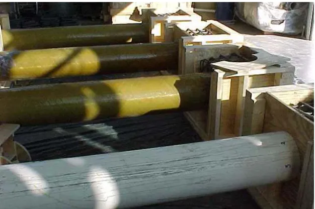
3.1 White Tube………..……… 75
3.2 Cross-Section of the White Tube….………... 75
3.3 Yellow Tube..……….. 76
3.6 Long Steel Cage……….. 77
3.7 Wooden Base Plate before Casting Concrete……….. 78
3.8 Formwork of an End Block………. 78
3.9 Overview of Specimens before Casting End Blocks………...……….. 79
3.10 Placement of a CFFT Beam-Column into an End Block………... 79
3.11 Specimens after De-Molding End Blocks……….…………. 80
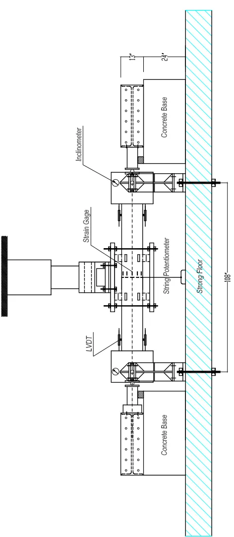
3.12 Instrumentation for Large-Scale Beam-Column Tests..……… 81
3.13 Load Cell to Measure Axial Load……….. 82
3.14 String Potentiometer……….. 83
3.15 Cross Sections of CFFT Beam-Column Specimens……….. 84
3.16 Wires of Internal Strain Gages………... 85
3.17 Location of External Strain Gages……….……… 85
3.18 Electrical Resistance Strain Gages………..………... 86
3.19 PI Gage………... 86
3.20 Potentiometer………. 87
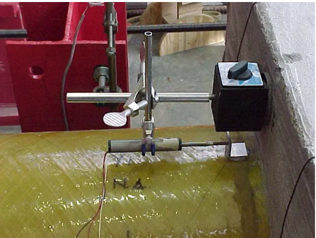
3.21 Inclinometer………... 87
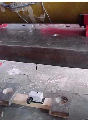
3.22 Monitoring of Support Movement………. 88
3.25 Overview of Large-Scale CFFT Beam-Column Tests………...……… 90
3.26 Horizontal Frame System with Threaded Rods……….……… 91
3.27 Steel Plate Embedded in End Block……….………. 91
3.28 Steel Plates and Vertical Loading System………. 92
3.29 Loading Regime for CFFT Beam-Column Tests………... 92
3.30 Distributed Cracking at the Top of Specimen Y1……….. 93
3.31 Crushing of White Tubes in Compression………. 93
3.32 Longitudinal Shear Splitting of White Tubes……… 94
3.33 Local Buckling of White FRP Tubes………. 94
3.34 Mid-Span Flexural Failure of Yellow Tubes………. 95
3.35 Normalized Load versus Deflection for Specimen W1………. 96
3.36 Normalized Load versus Deflection for Specimen W2………. 96
3.37 Normalized Load versus Deflection for Specimen W3………. 97
3.38 Normalized Load versus Deflection for Specimen Y1……….. 97
3.39 Normalized Load versus Deflection for Specimen Y2……….. 98
3.40 Normalized Load versus Deflection for Specimen Y3……….. 98
3.41 Normalized Envelope Curves of Load versus Deflection……….. 99
3.44 Axial Load versus Mid-Span Deflection for Specimen W3……….. 101
3.45 Axial Load versus Mod-Span Deflection for Specimen Y1……….. 101
3.46 Axial Load versus Mid-Span Deflection for Specimen Y2………... 102
3.47 Axial Load versus Mod-Span Deflection for Specimen Y3……….. 102
3.48 Normalized Load versus Steel Strain for Specimen W2……… 103
3.49 Normalized Load versus Steel Strain for Specimen W3……… 103
3.50 Normalized Load versus Steel Strain for Specimen Y2………. 104
3.51 Normalized Load versus Steel Strain for Specimen Y3………. 104
3.52 Cyclic Variation of Depth of Neutral Axial for Specimen W1……….. 105
3.53 Cyclic Variation of Depth of Neutral Axial for Specimen W2……….. 105
3.54 Cyclic Variation of Depth of Neutral Axial for Specimen W3……….. 106
3.55 Cyclic Variation of Depth of Neutral Axial for Specimen Y1………... 106
3.56 Cyclic Variation of Depth of Neutral Axial for Specimen Y2………... 107
3.57 Cyclic Variation of Depth of Neutral Axial for Specimen Y3………... 107
3.58 Normalized Total Moment versus End Rotations for Specimen Y1………. 108
3.59 Normalized Total Moment versus End Rotations for Specimen Y2…………... 108
3.60 Normalized Total Moment versus End Rotations for Specimen Y3…………... 109
3.63 Hoop Strains versus Longitudinal Strains at Bottom of Specimen W1….……… 110
3.64 Hoop Strains versus Longitudinal Strains at Top of Specimen W2……….. 111
3.65 Hoop Strains versus Longitudinal Strains at Bottom of Specimen W2….……… 111
3.66 Hoop Strains versus Longitudinal Strains at Top of Specimen W3……….. 112
3.67 Hoop Strains versus Longitudinal Strains at Bottom of Specimen W3….……… 112
3.68 Hoop Strains versus Longitudinal Strains at Top of Specimen Y1……….…….. 113
3.69 Hoop Strains versus Longitudinal Strains at Bottom of Specimen Y1…….……. 113
3.70 Hoop Strains versus Longitudinal Strains at Top of Specimen Y2……….…….. 114
3.71 Hoop Strains versus Longitudinal Strains at Bottom of Specimen Y2…….……. 114
3.72 Hoop Strains versus Longitudinal Strains at Top of Specimen Y3………...…… 115
3.73 Hoop Strains versus Longitudinal Strains at Bottom of Specimen Y3…….……. 115
3.74 Normalized Energy Dissipation Capacity……….………. 116
3.75 Ductility Factors for White Specimens………...………... 116
3.76 Displacement-Based Ductility Factor for Yellow Specimens………..…. 117
3.77 Pinching Effects Comparison ……....……… 117
3.78 Normalized Load versus Deflection for Secondary Monotonic Test of Y1…….. 118
3.79 Normalized Load versus Deflection for Secondary Monotonic Test of Y2…..… 118
3.82 Comparisons of CFFT with RC Beam-Columns………... 120
3.83 Typical GFRP and CFRP Specimens..………... 121
3.84 Test Setup for Stub Specimens……….. 121
3.85 Stub Test Equipment……….. 122
3.86 Loading Regimes for Stub Tests……… 122
3.87 Typical Failure Mode for a Single Layer Glass Wrap………... 123
3.88 Typical Failure Mode for Two-Layer Glass Wraps………... 123
3.89 Typical Failure Mode for a Single-Layer Carbon Wrap……… 124
3.90 Typical Failure Mode for a Two-Layer Glass Wrap……….. 124
3.91 Stress-Strain Response for Single Layer Glass Wraps……….……. 125
3.92 Stress-Strain Response for Two Layer Glass Wraps……….………… 125
3.93 Stress-Strain Response for Single Layer Carbon Wraps……….…….. 126
3.94 Stress-Strain Response for Two-Layer Carbon Wraps……….. 126
3.95 Typical Unloading Curves before Bend Point……….….. 127
3.96 Typical Unloading Curves after Bend Point……….. 127
3.97 Typical Reloading Curves from a Low Stress Level………. 128
3.98 Typical Reloading Curves from a High Stress Level……… 128
3.101 Test Setup for Tension Coupons………...………... 130
3.102 Test Setup for Compression Coupons………..………… 130
3.103 Typical Failure Modes for White Coupons in Tension……….….….. 131
3.104 Typical Failure Modes for Yellow Coupons in Tension………..……… 131
3.105 Typical Failure Modes for White Coupons in Compression………..…………. 132
3.106 Typical Failure Modes for Yellow Coupons in Compression………. 132
3.107 Monotonic Tests of White Coupons in Tension………..……… 133
3.108 Cyclic Test of White Coupon WTC1 in Tension……….……… 133
3.109 Cyclic Test of White Coupon WTC2 in Tension…….……… 134
3.110 Cyclic Test of White Coupon WTC3 in Tension……….……… 134
3.111 Monotonic Tests of White Coupons in Compression……….. 135
3.112 Cyclic Test of White Coupon WCC1 in Compression……… 135
3.113 Cyclic Test of White Coupon WCC2 in Compression……… 136
3.114 Monotonic Tests of Yellow Coupons in Tension………..………….. 137
3.115 Cyclic Test of Yellow Coupon YTC1 in Tension………..….………. 137
3.116 Cyclic Test of Yellow Coupon YTC2 in Tension………...………. 138
3.117 Cyclic Test of Yellow Coupon YTC3 in Tension………...………. 138
3.120 Cyclic Test of Yellow Coupon YCC2 in Compression……….……….. 140
3.121 Cyclic Test of Yellow Coupon YCC3 in Compression……….……….. 140
3.122 Reverse Cyclic Test of Yellow Coupon YCTC1……….……… 141
3.123 Reverse Cyclic Test of Yellow Coupon YCTC2……….……… 141
4.1 Monotonic Stress-Strain Envelope for FRP-Confined Concrete……… 158
4.2 Unloading and Reloading between Envelope Curve and Zero Stress………. 158
4.3 Regression Analysis of Unloading Slope…………...………. 159
4.4 Comparison of Predicted and Experimental Values of Unloading Slope..………. 159
4.5 Unloading Curve 1……….. 160
4.6 Unloading Curve 2……….. 160
4.7 Unloading Curve 3……….. 161
4.8 Unloading Curve 4……….. 161
4.9 Normalized Unloading Curves……… 162
4.10 Reloading from G1 Series Stubs……… 162
4.11 Reloading from G2 Series Stubs……… 163
4.12 Reloading from C1 Series Stubs……… 163
4.13 Reloading from C2 Series Stubs……… 164
4.16 Reloading from an Arbitrary Stress Level………. 166
4.17 Comparison of Proposed Model with Two-Layer CFRP Stub Unloaded to Zero Stress………...………... 167
4.18 Comparison of Proposed Model with Two-Layer CFRP Stub Unloaded to Non-Zero Stress………... 167
4.19 Comparison of Proposed Model with Three-Layer CFRP Stub Unloaded to Zero Stress………. 168
4.20 Comparison of Proposed Model with Three-Layer CFRP Stub Unloaded to zero and Non-Zero Stress………..………...………. 168
4.21 Monotonic Tension Model for White Tubes…..………... 169
4.22 Monotonic Compression Model for White Tubes………. 169
4.23 Monotonic Tension Model for Yellow Tubes………...…. 170
4.24 Monotonic Compression Model for Yellow Tubes………...……… 170
4.25 Proposed Cyclic Model for Yellow Tubes………. 171
4.26 Fiber Representation of Concrete-Filled FRP Tube……….. 171
4.27 Degrees of Freedom for 3-Node Element Based on Kirchhoff Beam Theory…... 172
4.28 Kinematics of the Section with Slippage………... 173
4.31 Comparison of Specimen Y2 with Proposed Model……….………. 174
4.32 Comparison of Specimen Y3 with Proposed Model……….………. 175
4.33 Comparison of Specimen W1 with Proposed Model………...………….. 175
4.34 Comparison of Specimen W2 with Proposed Model………...……….. 176
4.35 Comparison of Specimen W3 with Proposed Model………...…….. 176
5.1 Beam-Column Model for Parametric Study………... 188
5.2 Monotonic Stress-Strain Relations for Linear FRP, Non-Linear FRP and Grade 60 Steel………. 189
5.3 Hysteretic Stress-Strain Relations for the Linear FRP and Non-linear FRP…... 189
5.4 Effect of FRP Type without Internal Steel……….. 190
5.5 Effect of FRP Type with Internal Steel………... 190
5.6 Effect of Internal Steel Reinforcement for Linear FRP……….. 191
5.7 Effect of Internal Steel Reinforcement for Non-Linear FRP……….. 191
5.8 Effect of D/t Ratio for Linear FRP without Internal Steel……….. 192
5.9 Effect of D/t Ratio for Non-Linear FRP without Internal Steel……….. 192
5.10 Effect of D/t Ratio for Linear FRP with Internal Steel………. 193
5.11 Effect of D/t Ratio for Non-Linear FRP with Internal Steel………. 193
5.14 Effect of L/D Ratio for Linear FRP with Internal Steel……… 195
5.15 Effect of L/D Ratio for Non-Linear FRP with Internal Steel……… 195
5.16 Effect of P/Po Ratio for Linear FRP without Internal Steel……….. 196
5.17 Effect of P/Po Ratio for Non-Linear FRP without Internal Steel……….. 196
5.18 Effect of P/Po Ratio for Linear FRP with Internal Steel………... 197
5.19 Effect of P/Po Ratio for Non-Linear FRP with Internal Steel………... 197
5.20 Effect of D/t Ratio on the Envelope Curves for Linear FRP without Internal
Steel………... 198
5.21 Effect of D/t Ratio on the Envelope Curves for Non-Linear FRP without
Internal Steel……….……… 198
5.22 Effect of D/t Ratio on the Envelope Curves for Linear FRP with Internal Steel... 199
5.23 Effect of D/t Ratio on the Envelope Curves for Non-Linear FRP with Internal
Steel………... 199
5.24 Effect of L/D Ratio on the Envelope Curves for Linear FRP without Internal
Steel………..………. 200
5.25 Effect of L/D Ratio on the Envelope Curves for Non-Linear FRP without
Internal Steel……….……… 200
5.27 Effect of L/D Ratio on the Envelope Curves for Non-Linear FRP with Internal
Steel………...……… 201
5.28 Effect of P/Po Ratio on the Envelope Curves for Linear FRP without Internal
Steel………..………. 202
5.29 Effect of P/Po Ratio on the Envelope Curves for Non-Linear FRP without
Internal Steel……….……… 202
5.30 Effect of P/Po Ratio on the Envelope Curves for Linear FRP with Internal Steel. 203
5.31 Effect of P/Po Ratio on the Envelope Curves for Non-Linear FRP with Internal
Steel………...… 203
5.32 Effect of D/t Ratio on Cumulative Energy for Linear FRP without Internal Steel 204
5.33 Effect of D/t Ratio on Cumulative Energy for Non-Linear FRP without Internal
Steel……… 204
5.34 Effect of D/t Ratio on Cumulative Energy for Linear FRP with Internal Steel…. 205
5.35 Effect of D/t Ratio on Cumulative Energy for Non-Linear FRP with Internal
Steel………...……… 205
5.36 Effect of L/D Ratio on Cumulative Energy for Linear FRP without Internal
Steel………...……… 206
5.38 Effect of L/D Ratio on Cumulative Energy for Linear FRP with Internal Steel… 207
5.39 Effect of L/D Ratio on Cumulative Energy for Non-Linear FRP with Internal
Steel………...……… 207
5.40 Effect of P/Po Ratio on Cumulative Energy for Linear FRP without Internal
Steel………...……… 208
5.41 Effect of P/Po Ratio on Cumulative Energy for Non-Linear FRP without
Internal Steel………...……….. 208
5.42 Effect of P/Po Ratio on Cumulative Energy for Linear FRP with Internal Steel... 209
5.43 Effect of P/Po Ratio on Cumulative Energy for Non-Linear FRP with Internal
Steel………...……… 209
5.44 Effect of D/t Ratio on Ductility……….. 210
5.45 Effect of L/D Ratio on Ductility……… 210
5.46 Effect of P/Po Ratio on Ductility……… 211
5.47 Effect of D/t Ratio on Pinching……….. 211
5.48 Effect of L/D Ratio on Pinching……… 212
5.49 Effect of P/Po Ratio on Pinching……… 212
5.50 Sectional Equivalency of Linear FRP, Non-Linear FRP and Steel Tubes………. 213
5.53 Envelope Curves of Linear CFFT, Non-Linear CFFT, CFST and RC
Beam-Columns………...………. 215
5.54 Cumulative Energy Dissipation of Linear CFFT, Non-Linear CFFT, CFST and
RC Beam-Columns………... 215
5.55 Ductility and Pinching Behavior of Linear CFFT, Non-Linear CFFT, CFST and
RC Beam-Columns………..……. 216
A.1 Menegotto-Pinto Steel Cyclic Model………. A-4
CHAPTER 1
INTRODUCTION
1.1 Problem Statement
Environmental effects on concrete bridge pier columns and piles could significantly
deteriorate their long-term durability and structural integrity. The key problems are
permeability of concrete and corrosion of the embedded steel reinforcement. The concept of
using concrete-filled fiber reinforced polymer (FRP) tubes (CFFT) as columns or piles was
first introduced by Mirmiran and Shahawy (1995) to address these problems for the Florida
Department of Transportation. As an alternative to conventional reinforced concrete (RC)
columns or prestressed concrete piles, CFFT members can increase both durability and
strength of the structure. The benefits of CFFT members are twofold; protection of concrete
against harsh environmental effects especially in coastal areas, and strength enhancement of
concrete due to its confinement. Previous studies on confined concrete have shown that
lateral confinement with FRP tube not only increases its ultimate compressive strain (Samaan
et al. 1998), but also results in a compressive strength larger than the sum of the individual
strengths of concrete core and the tube (Fam 2000).
Due to these advantages, applications of CFFT systems have been studied extensively
in recent years. The focus, however, has been exclusively on the static and creep behavior of
such hybrid systems. Survey of damaged structures in recent earthquakes indicates that
catastrophic failure of an entire structure may be triggered by the failure of a few columns in
other hand, FRP materials are well known for their linear elastic behavior until failure. An
issue that has received little attention is the implications of using CFFT columns and piles in
seismic regions. This issue has design implications as to whether confinement alone can
provide adequate ductility for this type of structural members, or they need some internal
steel reinforcement, particularly in the plastic hinge regions of the member. Also some FRP
structures may exhibit non-linearity due to their laminate architecture and inter-laminar shear.
Another issue of great concern in FRP structures is the definitions of ductility. In RC
structures, ultimate displacements are measured against a reference displacement at the first
yield of steel reinforcement. However, there is no such yield criteria for FRP-RC members.
Therefore, one needs to develop a better understanding of the ductility measures that lend
themselves to non-yielding materials such as FRP.
The present study addresses the need for better understanding of the cyclic behavior
of CFFT and its components, FRP-confined concrete and FRP tubes. This study explores the
effects of FRP laminate architecture on its cyclic response to determine whether it is possible
to develop sizeable ductility and dissipate adequate energy in CFFT columns without any
internal steel reinforcement. Finally, the study will compare the cyclic behavior of CFFTs
with their RC and concrete-filled steel tube (CFST) counterparts.
1.2 Research Objectives
The following objectives were identified for this study:
1. Investigate cyclic response of FRP-confined concrete in uniaxial compression;
3. Investigate cyclic response of FRP laminates with different levels of fiber
reinforcement under uniaxial tension and compression loading;
4. Develop cyclic models for FRP laminates with different levels of fiber reinforcement
under uniaxial tension and compression loading;
5. Investigate the behavior of CFFT beam-columns, with different levels of fiber
reinforcement, and with or without internal steel reinforcement, under constant axial
loading and reverse transverse loading;
6. Employ an analytical tool to study the cyclic response of CFFT beam-columns under
different influencing factors, particularly the levels of fiber reinforcement and internal
steel reinforcement; and
7. Compare cyclic response of CFFT beam-columns with those of reinforced concrete
(RC) and concrete-filled steel tubes (CFST).
1.3 Research Approach
The CFFT system used in this research consists of three components, namely FRP
tube, concrete core and internal steel reinforcing bars. In order to study the cyclic behavior of
CFFT beam-columns, which can also cover some general conditions such as arbitrary axial
load levels, fiber orientations, and concrete strengths, the following four logically correlated
steps were carried out as the main elements of this research:
Firstly, the constitutive relations for each of the components were experimentally
investigated under cyclic loading. This included coupons of the FRP tube under uniaxial
uniaxial compression. Some experimental details were specially designed to help identify the
phenomenological behavior in order to accurately establish the cyclic models.
Secondly, the cyclic behavior of CFFT beam-columns was experimentally
investigated using a number of specimens with two different types of FRP tubes and three
different levels of internal steel reinforcement, including specimens with no internal
reinforcement. The specimens were loaded under constant axial loading and reverse
transverse loading in four point flexure. Special attention was given to the support conditions
and instrumentation to accurately capture the behavior of tested specimens.
Thirdly, the loading, unloading and reloading constitutive rules for all components of
CFFT were developed based on test observations, and regression analysis of the experiment
results. These models were then verified against the experimental data of the present study or
those of independent investigations.
Finally, a fiber element model was adopted and modified for use in the study of the
cyclic behavior of CFFT beam-columns. The cross section of CFFT was discretized into fiber
elements of FRP, concrete, and reinforcing bars. The constitutive laws for each type of
element was used accordingly to establish the overall cyclic response of the beam-columns.
The model was verified against the experimental results of the present study. It was then used
for a parametric study of different influencing factors, including type of FRP tube,
reinforcement ratio of internal steel (if any), diameter-to-thickness and length-to-diameter
ratios of the tube, and the level of axial loads as a fraction of the axial capacity of the column.
The model was also used to compare the cyclic behavior of CFFT beam-columns against its
1.4 Organization of the Dissertation
This dissertation consists of six chapters and an appendix, as follows:
Chapter 1 (this chapter) highlights the problem statement, and the significance,
objectives and methodologies of the research undertaken in this study. Chapter 2 presents a
literature review of the previous work on modeling of concrete confined with FRP, modeling
of FRP laminates, experimental work on CFFT beam-columns, and evaluation criteria for
seismic performance of RC structures in general. Chapter 3 summarizes the results of the
experimental work on FRP-confined concrete stubs and the FRP coupons under cyclic
uniaxial loading, and the CFFT beam-columns under constant axial loading and reverse
transverse loading. Chapter 4 presents the cyclic models developed for the components of the
CFFT systems, namely FRP-confined concrete and the FRP tube. It also discusses a fiber
element model that was utilized to study the cyclic behavior of CFFT beam-columns. The
described models are verified against experimental data. Chapter 5 reports on parametric
studies of CFFT beam-columns under different factors affecting their cyclic behavior. It also
compares the cyclic response of CFFT beam-columns with their equivalent RC and CFST
counterparts. Chapter 6 summarizes the research undertaken in this study, and provides
concluding remarks in addition to recommendations for future research. Appendix A
describes details of the fiber element model used in this study, and the hysteretic model that
CHAPTER 2
LITERATURE REVIEW
2.1 Introduction
Cyclic performance of CFFT beam-columns is a new research area that has not been
explored in the past. Literature review in this chapter seeks relevant studies for various
aspects of the problem, including confinement models for concrete, cyclic response of
unconfined and confined concrete, behavior of FRP laminates, applications of CFFT
members, and evaluation criteria for seismic performance of concrete structures.
2.2 Confinement Modeling of Concrete
Over the years, a number of confinement models have been developed for concrete.
Until a few years ago, majority of the models were developed and calibrated for concrete
confined by transverse steel. Only in recent years, a need has been recognized for modeling
of FRP-confined concrete. In this section, a brief overview of the previous work on the
subject is presented.
The most widely used model for concrete confined by steel spirals or ties is that of
Mander et al. (1988), whose simple equations describe the entire stress-strain curve. It also
accommodates cyclic loading and different strain rates. An energy balance approach is
adopted to predict the ultimate compressive strain of concrete based on the first fracture of
the transverse steel reinforcement. Fardis and Khalili (1982) made the first attempt at
re-applicable to concrete stubs wrapped with glass FRP wires. Priestley et al. (1992) studied the
use of glass FRP wraps to enhance flexural and shear performance of seven RC bridge
columns in seismic regions. Test results showed that properly designed FRP wraps could
prevent lap-splice failures in plastic hinge regions, and provide sufficient shear strength for
columns. They slightly modified the model of Mander et al. (1988) to make it applicable to
FRP-wrapped concrete columns. On the other hand, Saadatmanesh et al. (1994) directly used
the model of Mander et al. (1988) with no modification, and conducted a parametric study of
circular and rectangular columns strengthened with glass or carbon FRP straps. They did not
verify their analytical results with any test data.
The first tests on concrete-filled FRP tubes were carried out by Kargahi (1995), and
showed significant improvement in strength and ductility of concrete. Mirmiran and
Shahawy (1995) described the deficiencies of the model of Mander et al. (1988) for
FRP-confined concrete, and developed an iterative strategy to ensure strain compatibility between
the concrete core and the FRP wrap in the circumferential direction. The concept of
enforcing strain compatibility was later adopted by other investigators (Spoelstra and Monti
1999). Later on, Harmon et al. (1998) articulated the reason why the energy balance
approach of Mander et al. (1988) does not apply to FRP-confined concrete. They used
fracture mechanics instead to model confined concrete. Mirmiran and Shahawy (1997a,
1997b) reported on the unique dilation characteristics of FRP-confined concrete. In an effort
to combine the confining effects of internal steel hoops and external FRP wraps, Restrepol
and DeVino (1996) proposed analytical expressions based on the model of Mander et al.
Picher et al. (1996) examined the effect of fiber orientation on FRP-confined concrete.
They concluded that different fiber orientations may affect stiffness and strength of concrete,
yet its ductility remains almost the same. They also recommended rounding the corners of
square or rectangular sections to improve their confinement effectiveness. Bavarian et al.
(1996) studied the effect of different fiber types, including glass and aramid, and showed that
the behavior of confined concrete directly depends on the stiffness and strength of the FRP
jacket. Mastrapa (1997) reported that adhesive bond between FRP and concrete does not
significantly affect the strength or ductility of confined concrete. El Echary (1997) assessed
the effect of length-to-diameter ratio of the FRP tube on the confinement of concrete, and
reported a maximum of 20% strength reduction at a length-to-diameter ratio of 5:1.
Miyauchi et al. (1997) tested a number of carbon-wrapped concrete stubs, and
proposed a new model that consisted of a parabola and a tangential straight line at the end.
The model was used to perform a time history response analysis for existing RC pier
columns strengthened with FRP and subjected to earthquake motion. The analytical results
showed that the existing pier columns with only two layers of carbon wrap could withstand
the Southern Hyogo Prefecture earthquake.
Watanabe et al. (1997) and Zagers (1998) used finite elements for the analysis of
FRP-confined concrete. Samaan et al. (1998) proposed a bilinear model to trace the entire
stress-strain curve for the FRP-confined concrete in monotonic compression. The model
correlates the dilation rate of concrete with the hoop stiffness of the FRP. The parameters of
the model are directly related to the material properties of the FRP and the concrete core. In
2.3 Cyclic Behavior of Plain and Confined Concrete
While the ultimate strength theory was being developed as a new method to analyze
RC sections under monotonic loading, Sinha et al. (1964) began their pioneering work on the
cyclic behavior of concrete. Based on tests of 36 plain concrete cylinders, they suggested that
the envelope curve may be considered unique for each strength level of concrete. They also
defined a “shakedown limit” for the stress-strain relations of plain concrete, as the locus of
points where the reloading and unloading portions of each cycle cross. While stressing above
this shakedown limit would lead to additional strains, unloading and reloading at or below
this limit would not develop permanent strains. Later, Karsan and Jirsa (1969) confirmed the
hypothesis of unique envelope curve for concrete. They also studied the distribution of
common points, where the reloading and unloading paths cross each other. They concluded
that plain concrete would fail under repeated loading, if stresses exceed 63% of the
compressive strength of concrete.
Using theory of internal crack propagation, Popvics (1970) showed that rate of loading,
number cycles, and the stress level greatly influence short-term stress-strain response of
concrete. Park et al. (1972) implemented the cyclic stress-strain curve for concrete and steel
in a computer program to develop the hysteretic moment-curvature response of RC members.
Desayi et al. (1979) and Shah et al. (1983) both confirmed the unique envelope curve
for confined concrete. However, the latter found two exceptions, when cyclic load is applied
slowly or when the number of cycles to failure is too large. In those cases, the total strain
under cyclic load may exceed the envelope curve under monotonic load. However, these
As stated earlier, the model of Mander et al. (1988) describes detailed rules of
unloading and reloading for confined concrete. In recent years, Bahn and Hsu (1998)
proposed a new model for stress-strain behavior of concrete under cyclic loading. Also,
Cabrera (1996) extended the monotonic model of Samaan et al. (1998) for the FRP-confined
concrete, and incorporated the unloading and reloading rules similar to those in the model of
Mander et al. (1988). The model was then used to study the hysteretic response of
FRP-confined concrete. She noted significant pinching in the response of FRP-FRP-confined concrete.
However, no experimental data was available at the time to verify her analytical results.
2.4 Modeling of FRP Laminates
Mechanical properties of polymers are highly dependent upon the magnitude, rate and
frequency of loading as well as the ambient temperature. Therefore, it is not feasible to
obtain a single stress-strain curve for polymers. Figure 2.1 shows a typical set of such curves
for different rates of loading. As the loading rate increases, the response becomes more linear,
whereas at sufficiently low rates of loading considerable plastic flow and yielding is evident.
Higher temperatures generally result in a characteristic behavior similar to that for low rates
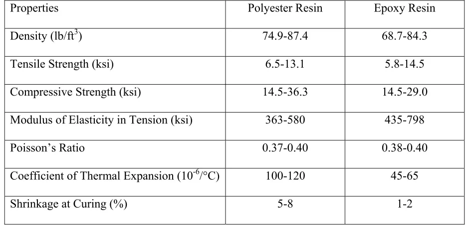
of loading. Tables 2.1 provides mechanical properties for two typical thermoset resins:
polyester and epoxy.
Adding fibers to the polymer matrix greatly reduces the above effects. The main
function of the fibers is to carry the majority of the load applied to the composites, while the
matrix distributes the loads between the fibers. Figure 2.2 compares typical tensile
Mechanical properties of FRP materials depend on the fabrication technique, type and
properties of its components, particularly the fibers, and the volume fraction of the fibers in
the overall mix. Pressure or vacuum molding generally results in a higher fiber volume
fraction as compared to hand lay-up. While the ultimate strength of FRP materials depends
on the strength and modulus of the fibers, its in-service properties are functions of the matrix.
Fibers generally exhibit linear elastic behavior, while resins are visco-elastic or visco-plastic.
As such, linear elastic behavior of fibers is generally the dominant factor in the response of
unidirectional FRP materials loaded in the direction of the fibers. However, a nonlinear
behavior is often observed in the off-axis direction, under certain fiber orientations and fiber
volume ratios, as the matrix resists the pull out of broken fibers in shear.
FRP materials are laminate structures made up of a stack of lamina with various fiber
orientations. Bonding of the plies or layers of a laminate is often made with the same matrix
used in the lamina. In the filament-winding of a tube, for example, each fiber orientation
represents a ply, and the entire laminate is made with the same matrix in a single batch.
Figure 2.3 shows the different modes of failure in laminate structures, including fiber rupture,
transverse or longitudinal cracking of the matrix, debonding at the fiber-matrix interface, and
delamination between different layers.
Because of their inherent heterogeneous and anisotropic nature, FRP materials are
studied from two points of view: micromechanics and macro-mechanics. The former is a
study of FRP at the level of its constituent materials and their interaction at a microscopic
scale, whereas the latter is a study of FRP materials at a macroscopic scale, assuming
can be engineered or tailored for optimum properties in different directions. The tailoring
process includes selecting appropriate constituents, fiber volume fraction, fiber orientation,
and the stacking sequence of plies.
Figure 2.4 shows fibers uniformly dispersed within a matrix in a unidirectional
lamina. Perfect bond is assumed at the interface between fibers and the matrix. The lamina,
therefore, has orthotropic properties with the greatest stiffness and strength in the direction of
fibers. The primary modulus of elasticity E11 can be calculated as
f f m mV E V
E
E11= + (2.1)
where E and V are the elastic modulus and volume fraction, respectively, and subscripts f and
m denote fibers and the matrix, respectively. The above equation, known as the “law of
mixture,” can be derived from the resultant axial force P11in the lamina, as given by
f
m P
P
P11= + (2.2)
where Pm and Pf are the resultant forces in the matrix and the fibers, respectively. The equation can be written in terms of stresses as
f f m
mA A
A σ σ
σ11 11= + (2.3)
where σ and A are the stress and area identified with subscripts for each phase, and therefore,
in terms of volume fractions, it can be written as
f f m mV σ V
σ
σ11= + (2.4)
from which, one can derive Equation (2.1), assuming strain compatibility. Similarly, the
Poisson's ratio ν12 of the lamina can also be written as
f f m mV ν V
ν
where νm and νf are the Poisson’s rations for the matrix and the fibers, respectively. The transverse modulus of elasticity E22 can be written as
(
m f f m)
m
fE E V E V
E
E22 = + (2.6)
Finally, the shear modulus G12 is expressed as
(
m f f m)
m
fG G V G V
G
G12 = + (2.7)
At the macromechanics level, the stress-strain relationship of uni-directional lamina
can be sufficiently described using the generalized Hooke's law, as
= 12 31 23 3 2 1 66 55 44 33 23 13 23 22 12 13 12 11 12 31 23 3 2 1 0 0 0 0 0 0 0 0 0 0 0 0 0 0 0 0 0 0 0 0 0 0 0 0 γ γ γ ε ε ε τ τ τ σ σ σ C C C C C C C C C C C C (2.8)
where σi (i = 1, 2, 3) and εi (i = 1, 2, 3) are the normal stresses and strains in the three principal material directions (see Figure 2.4), respectively, and τij (i,j = 1, 2, 3) and γij (i,j = 1, 2, 3) are the shear stresses and strains, respectively, and Cij are stiffness coefficients. For a thin orthotropic shell, transverse strains are negligible, and therefore, it can be shown that
0 0 0 0 0 0 3 3 23 23 13 13 = ⇒ = ≠ ⇒ = ≠ ⇒ = σ ε τ γ τ γ (2.9)
As such, the constitutive equations can be simplified in the principal material
directions of the orthotropic material as
=
1 11 12 1
where Qij denote the reduced stiffness of an orthotropic lamina, and are related to the engineering properties measured along the principal directions, as given by
21 12
1 11
1−ν ν
= E Q ; 21 12 2 12 12
1 ν ν
ν − = E Q ; 21 12 2 11
1−ν ν
= E
Q ; Q66 =G12 (2.11)
The above relations were developed for the principal materials directions in an
orthotropic material. However, the principal directions of orthotropy often do not coincide
with the geometric coordinate system, as evident in a helically wound glass FRP tube (see
Figure 2.5). Transformation from the principal materials direction to an arbitrary coordinate
system can easily be done, as shown in Figure 2.6, using the following equation:
− ⋅ − ⋅ ⋅ ⋅ − = 12 2 1 2 2 2 2 2 2 sin cos cos sin cos sin cos sin 2 cos sin cos sin 2 sin cos τ σ σ ϕ ϕ ϕ ϕ ϕ ϕ ϕ ϕ ϕ ϕ ϕ ϕ ϕ ϕ τ σ σ θ θ x x (2.12)
where ϕ is the angle of rotation. Similar transformations can be applied to the strains and
material properties of the shell.
As stated earlier, nonlinearity in the off-axis direction could be significant. Hahn and
Tsai (1973) used a complementary energy density function to derive nonlinear relations for
in-plane shear. Hahn (1973) extended the nonlinear theory of unidirectional lamina to that of
laminated composites. Lifshitz (1998) studied the shear modulus of T300-934 graphite/epoxy
lamina with four layers at fiber orientations of ±45º. Hu (1993) reported that unidirectional
FRP may exhibit severe nonlinearity in its in-plane shear stress-strain relation. Also, some
deviation from linearity may be observed under in-plane transverse loading, but the degree of
shear tests were performed on off-axis coupons cut at different angles of 0°, 15°, 30°, 45°,
60°, and 90°. The overall linear elastic properties were identified along with the nonlinear
stress-strain behavior under in-plane multi-axial tension and compression loading. The
material had a lower ultimate tensile stress and initial stiffness in tension compared to the
corresponding values from compression tests, regardless of thickness and orientation. This
was attributed to the existing voids and micro-cracks that are more pronounced in
matrix-mode tensile loading. The difference between the compressive and tensile properties
increased for off-axis angles approaching 90°.
2.5 Applications of CFFT Beam-Columns
In 1995, Mirmiran and Shahawy developed the concept of concrete-filled FRP tubes
to address the corrosion problems for the Florida Department of Transportation. Cabrera
(1996) conducted several shear tests on short beams with square sections. Half of the beams
had shear connectors, while the other half had smooth internal surface. The beams were
loaded to failure in a four-point loading test. Test results demonstrated that slippage between
FRP and concrete could be completely arrested using shear connectors. She also conducted a
study on the seismic performance of concrete-filled FRP tube based on a cyclic stress-strain
model. Mirmiran et al. (1998b) presented the design, fabrication and testing of the new
hybrid column with internal shear connector ribs in the longitudinal and transverse directions.
Based on the experimental interaction diagram for the proposed column, Mirmiran et al.
(1999a) showed the new system to be equivalent to RC columns with over 5% steel
Seible et al. (1995) studied the composite carbon shell systems for bridge columns
under seismic loads. The new structural system was evaluated experimentally under
simulated seismic loads using pilot test units which incorporated different design
assumptions with the objective of matching or exceeding the performance of conventionally
reinforced concrete columns. Consequently, a rational and comprehensive design procedure
was developed to incorporate the mechanical characteristics of advanced composite materials
into the design methodology conventional columns.
Mirmiran et al. (2000a) further showed that off-the-shelf tubes with no surface
preparation could be comparable to reinforced or prestressed concrete columns. The CFFT
system, with an equivalent reinforcement ratio of only 1.4%, performed better than a 6%
reinforced concrete section or a prestressed concrete section with 33% more concrete area.
Fam (2000) also studied the behavior of concrete-filled FRP tubes under axial/flexural
loading conditions. The specimens ranged from 3.5 to 34 ft span length and from 3½ to 37 in
diameter. Mirmiran et al. (2000b) investigated the enhancement of serviceability, strength
and ductility of concrete-filled tubes under flexural loads by partial prestressing of the
section. They recommended to keep the effective prestress within 10%-25% of the
unconfined strength of concrete core, and to limit tendon eccentricities to the kern distance to
avoid tensile stresses at the interface of the concrete core and the FRP tube, unless the tube is
equipped with ribs or shear connectors.
Davol et al. (2001) extended the studies of concrete-filled tubes to carbon FRP
laminates. They tested two different laminate structures. The first shell with a lay-up of [90o,
longitudinal strain of 0.55%. The second shell with a lay-up of [90o
2, ±10o2, 90o, ±10o2, 90o,
±10o, 90o2, ±10o, 90o3] failed in compression at a much higher strain of 0.83%.
Fan et al. (2000) studied the seismic performance of reinforced concrete columns
confined by FRP tube under low cycle reverse loading. The FRP tubes acted as formwork as
well as lateral confining system. There was a 2 in. gap between FRP tubes and the footing of
columns. The experimental results showed that the FRP tube did not increase the capacity of
the column, but it greatly enhanced its ductility ratio up to 10.
Yuan et al. (2002) proposed a novel hybrid GFRP tube filled with concrete. They
reported that the FRP tube enhanced the strength of concrete by 2½ times. Fiber orientations
in the tubes were ±45°. Coupons of the tube were cut and tested under monotonic tension and
compression. Tests showed a bilinear response in tension (Figure 2.7) and compression
(Figure 2.8), with similar moduli of elasticity. However, the ultimate tensile strength was
lower than the ultimate compressive strength.
2.6 Evaluation Criteria for Seismic Performance
In search of finding appropriate measures for CFFT systems, several criteria for
evaluating seismic performance of a concrete structure are discussed in this section.
2.6.1 Ductility
Ductility of a member is defined as its ability to sustain inelastic deformations prior to
collapse, without significant strength or stiffness degradation. A ductile system displays
selected deformation component may be deflection, curvature, or rotation. However, such
definition of ductility is not directly applicable to FRP or FRP-reinforced concrete (FRP-RC)
members. Mirmiran et al. (1999b) summarized the following two ductility factors for
FRP-RC members, especially CFFT members:
1. The yield-based ductility index follows the conventional definition of ductility, as
y u
D ∆
∆ =
µ (2.13)
where ∆u and ∆y are the ultimate and yield deflections, respectively. The ultimate deflection is generally considered to be the deflection at the time of collapse as long
as the load drops is no more than 15% of the capacity of the member (Park and
Paulay 1975). The yield deflection is defined as that of an equivalent elasto-plastic
system with the same elastic stiffness and ultimate load as those of the real system
(Figure 2.9). This definition was first suggested by Park (1989) for use with nonlinear
materials or when various parts of a system commence their yielding at different load
levels.
2. The energy-based ductility index takes into account the portion of the total
absorbed energy, ETOT (i.e., toughness), that is elastically released at the time of failure, EEL. This definition was first suggested by Naaman and Jeong (1995) for concrete beams prestressed with FRP tendons, and is given by
+
= 1
2 1
*
EL TOT D
E E
µ (2.14)
of the load-deflection curve (Figure 2.10). This has been justified for CFFTs by several
uniaxial cyclic load tests (Mirmiran and Shahawy 1997a). Both ductility measures
(yield-based and energy-(yield-based ratios) indicate that whereas CFFTs are not as ductile as the
conventional RC columns in the tension failure region, they are quite comparable to RC
sections at higher levels of axial load.
Under cyclic loading, due to opening and closing of crack and apparent stiffness
degradation, performance of concrete structures depends greatly on the loading regime. Kaku
and Asakusa (1991) proposed the concept of the cumulative ductility factor, which is used to
evaluate the deformability and energy dissipation capacity of concrete structures. As shown
in Figure 2.11, the cumulative ductility factor (CDF) may be defined as the sum of the
ductility ratios at each loading cycle up to the failure of the structure, and normalized as
follows:
∑
×
=
(
n
δ
n)
/
δ
1CDF
(2.15)2.6.2 Stiffness Degradation
Numerous experimental studies have shown that repeated cyclic loading may cause
three distinct effects in the response of an RC structure: (a) reduction in stiffness, (b)
deterioration in strength, and (c) a characteristic known as pinching, which is caused
primarily by bond-slip behavior of reinforcement. Mander et al. (1988) studied the cyclic
behavior of steel-RC columns, and put forth a cyclic model for confined RC sections taking
into account the first two of these distinct effects, as shown in Figure 2.12, and described
2. When RC column is reloaded again from a certain reloading strain of εroto the same unloading strain, εun, there is a strength reduction from fun to fnew, which leads to a stiffness degradation for the confined concrete; and
3. After the transition region, the reloading curve finally returns to the envelope curve of
the monotonic response.
2.6.3 Pinching Effect
When concrete is subjected to cyclic loading, the shape of its stress-strain curve is
greatly influenced by the shape of the stress-strain loop for the steel, because the applied
moment is carried largely by the reinforcement placed in the section, especially after the first
yielding. The Bauschinger effect of steel makes the stress-strain relationship curved and
accompanied by some rounding. The so-called “pinching effect” appears in the hysteretic
stress-strain response of some RC members, when subjected to cyclic loading. It reflects the
strength decay due to several factors, primarily the bond-slip of the reinforcement, yielding
of the reinforcement, and the loss of shear resistance after formation of cracks (Monti and
Spacone 2000). As shown in Figure 2.13, the pinching effect implies that there is less energy
dissipation per cycle than in the generally assumed parallelogram of classical elasto-plastic
behavior.
The pinching effect is often a direct result of bar slippage. This effect is especially
important in structures predominantly controlled by shear. When there is considerable
Since there is no quantitative measure for the pinching effect, in this dissertation it is
defined as the ratio between the maximum width of the hysteretic response and its width at
the origin. The higher the ratio is, the larger the pinching effect would be.
2.6.4 Energy Absorption Capacity
Energy absorption capacity was first adopted as a measure of seismic performance by
Gosain et al. (1977), who proposed a simple cumulative energy ratio, as follows:
∑
=
i y y
i i e
F
F
D
δ
δ
(2.16)
where Fi and δi are the force and deflection at the ith loop, respectively, and Fy and δy are the
force and deflection at the yield point, respectively. Only the hysteretic loops for which Fi/Fy
> 0.75 are included in the summation. This is based on the assumption that when the peak
force has dropped below 75% of the yield force, the remaining capacity of the member may
be considered negligible.
Nmai and Darwin (1986) used the concept of energy dissipation index Di to evaluate the cyclic performance of an RC member. The energy dissipation index normalizes the total
dissipated energy E with respect to the elastic energy Ey at the initial yield for an equivalent full span beam, and is given by
] ) ( 1 [ 5
.
0 ' 2
s s y
y y
i
A A P
E E
E D
+ ⋅ ∆ ⋅ ⋅ =
= (2.17)
face of the support, and A’s is the area of bottom reinforcement at the face of the support. From the above equation, it is clear that the higher the value ofDi, the better the performance
of the member would be under seismic loads.
2.6.5 Damage Index
The best known and most widely used damage index is the cumulative index
suggested by Park and Ang (1985) and summarized by Williams and Sexsmith (1995), which
consists of a simple linear combination of normalized deformation and energy absorption:
u y e u m
F dE D
δ
β
δ
δ
+∫
= (2.18)
where δm is the maximum deformation experienced, δu is the ultimate deformation under monotonic loading, Fy is the calculated yield strength, dE is the dissipated energy increment, and
w t
e n
d
l ρ ρ
β =(−0.447+0.73 +0.24 0 +0.314 )⋅0.7 (2.19)
where l/d is the ratio of shear span to beam depth, no is the normalized axial force, ρw is the reinforcement ratio for confining steel, and ρt is the reinforcement ratio for the longitudinal steel.
The above damage index consists of two terms. The first term is a simple,
pseudo-static displacement measure. It takes no account of the cumulative damage, which is
including some instances of shear and bond failure. Park et al. (1985) suggested the use of D
= 0.4 as a threshold value between repairable and irreparable damage, while the same authors
later (Park et al. 1987) suggested a more detailed classification, as reported in Table 2.2.
A number of difficulties arise in using Equation (2.18). A major problem is the
determination of the ultimate deformation δu and the strength deterioration parameter βe. Park and Ang (1985) proposed regression equations for the two parameters related to the
confining reinforcement ratio and material strengths. However, the equation for βe yields very small values, so that the energy term makes a negligible contribution to the overall
index, which therefore takes virtually no account of the hysteretic effect. In this dissertation,
no attempt was made at developing an equivalent damage index for the CFFT specimens, due
Table 2.1 Mechanical Properties of Typical Thermoset Resins (Hollaway, 1990)
Properties Polyester Resin Epoxy Resin
Density (lb/ft3) 74.9-87.4 68.7-84.3 Tensile Strength (ksi) 6.5-13.1 5.8-14.5
Compressive Strength (ksi) 14.5-36.3 14.5-29.0
Modulus of Elasticity in Tension (ksi) 363-580 435-798
Poisson’s Ratio 0.37-0.40 0.38-0.40
Coefficient of Thermal Expansion (10-6/°C) 100-120 45-65 Shrinkage at Curing (%) 5-8 1-2
Table 2.2 Damage Index Classifications (Park and Ang 1985)
Category Damage Index Damage Level
1 D < 0.1 No damage or localized minor cracking
2 0.1 ≤ D < 0.25 Minor damage: light cracking throughout
3 0.25 ≤ D < 0.4 Moderate damage: severe cracking, localized spalling
4 0.4 ≤ D < 0.8 Severe damage: concrete crushing, reinforcement exposed
Figure 2.1 Mechanical Properties of Polymers (Hollaway 1990)
Figure 2.2 Mechanical Properties of Fibers 0
100 200 300 400 500 600
0 0.5 1 1.5 2 2.5 3 3.5 4
Strain (%)
Stres
s (k
si
)
Carbon (High Strength) Carbon
(High Modulus)
S-Glass
E-Glass
Stress
(GPa)
Figure 2.1 Mechanical Properties of Polymers (Hollaway 1990)
Figure 2.2 Mechanical Properties of Fibers 0
100 200 300 400 500 600
0 0.5 1 1.5 2 2.5 3 3.5 4
Strain (%)
Stres
s (k
si
)
Carbon (High Strength) Carbon
(High Modulus)
S-Glass
E-Glass
Figure 2.3 Modes of Failure in a Laminate (Berthelot 1995)
Figure 2.4 Macromechanics of FRP Composites (Hollaway 1990) Figure 2.3 Modes of Failure in a Laminate (Berthelot 1995)
Figure 2.5 Helically Wound Fiber Reinforced Cylindrical Shell (Jones 1975)
Figure 2.6 Positive Rotation of Principal Material Axes from Arbitrary XY axes (Jones 1975)
Figure 2.5 Helically Wound Fiber Reinforced Cylindrical Shell (Jones 1975)
Figure 2.7 Tensile Test Result of GFRP Coupons (Yuan et al. 2002)
Figure 2.8 Compressive Test Result of GFRP Coupons (Yuan et al. 2002)
Strain
Strain
Stress (MPa)
Stress (MPa)
Figure 2.7 Tensile Test Result of GFRP Coupons (Yuan et al. 2002)
Figure 2.8 Compressive Test Result of GFRP Coupons (Yuan et al. 2002)
Strain
Strain
Figure 2.9 Definition of Displacement-Based Ductility (Park and Paulay 1975, Mirmiran et al. 1999) Figure 2.9 Definition of Displacement-Based Ductility
F
ig
ur
e 2
.1
1 C
umu
la
ti
ve
D
uc
tilit
y F
ac
to
r
(K
ak
u
an
d
As
ak
us
a 1
99
1
)
F
ig
ur
e 2
.1
1 C
umu
la
ti
ve
D
uc
tilit
y F
ac
to
r
(K
ak
u
an
d
As
ak
us
a 1
99
1
εc
fc
(εun, fnew)
(εun, fun)
(0, 0)
Figure 2.12 Stiffness Degradation
Figure 2.13 Pinching Effects (Budek et al. 2002)
High Pinching Low Pinching
εc
fc
(εun, fnew)
(εun, fun)
(0, 0)
Figure 2.12 Stiffness Degradation
Figure 2.13 Pinching Effects (Budek et al. 2002)
CHAPTER 3
EXPERIMENTAL WORK
3.1 Test Plan
A detailed experimental program was carried out with three different components, as
follows, to evaluate the cyclic behavior of concrete-filled FRP tubes (CFFTs):
1. Beam-column tests: Six (6) large-scale CFFTs with two different types of FRP tubes
and three different levels of internal steel reinforcement were tested under constant
axial compression loading and reversed cycles of transverse loading in four-point
flexure. The objective of these tests was to establish the cyclic response of hybrid
FRP-concrete columns with and without steel reinforcement.
2. Stub tests: Twenty-four (24) short stubs of FRP-wrapped concrete were tested under
cycles of loading and unloading in uniaxial compression. The objective of these tests
was to develop the cyclic model for concrete confined with different amounts of FRP.
3. FRP coupons: Twenty-five (25) coupons cut from the two types of FRP tubes were
tested under cycles of loading and unloading in uniaxial tension or compression, as
well as reverse cyclic loading in tension and compression. The objective of these tests
was to establish the material models for the FRP tubes.