A STATISTICAL AND FINITE ELEMENT MODELLING APPROACH
USED IN THE DERIVATION OF MODERATOR GRAPHITE
BEHAVIOUR
M Fahad1, G Hall1, K McNally2, B J Marsden1, P Mummery1, and N Warren2
1Nuclear Graphite Research Group, School of MACE, The University of Manchester, Manchester,
England M13 9PL
2Statistical Modelling Team, Mathematical Sciences Unit, Health and Safety Laboratory, Harpur Hill,
Buxton, England SK17 9JN
ABSTRACT
In Advanced Gas-cooled Reactors, fast neutron irradiation and radiolytic oxidation cause complex dimensional and material properties changes in the graphite moderator bricks. These changes, primarily dimensional change and irradiation creep, have an effect on the internal stresses produced in the graphite bricks that could lead to cracking. Stresses in the moderator brick can be predicted using the finite element method in combination with constitutive equations derived from experimental data. Although much data are available for changes in an inert environment, there is a lack of data for changes due to combined fast neutron irradiation and radiolytic oxidation. This paper presents a combined finite element and statistical modelling approach to determine the behaviour of graphite in an irradiation and oxidizing environment from reactor inspection data.
KEYWORDS
Nuclear Graphite, Fast Neutron Irradiation, Radiolytic Oxidation, Finite Element Modelling, Bayesian emulator.
INTRODUCTION
Nuclear graphite in an Advanced Gas Cooled Reactor (AGR) acts as a moderator and forms channels for fuel and control rods and channels for coolant. Thus, it is important that the graphite moderator bricks retain their structural integrity. Fast neutron irradiation causes complex dimensional and material properties changes in the graphite moderator bricks. According to Kelly (1982) all of the graphite properties will change when it is in a reactor. Furthermore, fast neutron irradiation causes dimensional changes which lead to a buildup of internal stresses within the brick. Nuclear graphite also undergoes “irradiation creep” (Chang, 1974), which relieves the internal stresses to some extent. However, the stresses can still build up and the structural integrity of the bricks may eventually be compromised.
Many studies have been conducted to study the behaviour of nuclear graphite under fast neutron irradiation. Most of the reactors in operation in UK are carbon dioxide cooled including the AGRs. Although, there are advantages of using carbon dioxide as a coolant including ease in the variation of the density of the coolant and independence of phase change of the gas on reactor operating conditions (Tsang and Marsden, 2006), the graphite undergoes radiolytic oxidation in addition to the fast neutron irradiation. The radiolytic oxidation leads to weight loss and develops further internal porosity which significantly reduces the strength (Neighbour, 2001).
2
channels. However, there are limited data available for dimensional changes and irradiation creep under a combined effect of an irradiating and oxidising environment and to fluences that are applicable to the AGR. The measurement of the brick shape changes are being carried out at regular intervals during the reactor outage using a device called Channel Bore Measurement Unit (CBMU).The Finite Element Analysis (FEA) of graphite components in a reactor are normally carried out using empirical relationships derived from MTR data and tuned to trepanned data. The predicted stresses can be compared with the strength data from MTR programs and trepanning campaigns to give an indication of the likelihood of cracking. Current analyses predict that the moderator bricks should not be cracking although cracks have been observed in operating AGRs. One possible explanation for this discrepancy is that the predicted stresses are incorrect due to the uncertainties in the modelling of dimensional change and irradiation creep in a combined fast neutron irradiation and radiolytic oxidation environment. At present the predicted stresses cannot be validated against the actual stresses in the moderator bricks. However, a large amount of reactor data in the form of CBMU data does exist and may lend itself to the validation or improvement of component behaviour.
The UK’s Office for Nuclear Regulation established the AGR Brick Cracking Network (AGR BCN) with the aim of investigating the cracking phenomenon and improving our understanding of the causes. The AGR BCN consists of the Health and Safety Laboratory (HSL), the University of Birmingham (UoB) and the University of Manchester (UoM). This paper presents a combined effort of HSL and UoM to devise a methodology that can be used to improve the Finite Element Modeling (FEM) assessments for irradiated and oxidized graphite. This is carried out through a calibration of FE models to experimental and CBMU measurements, using a statistical emulator. The model could reduce the uncertainties in the prediction of future behaviour and ultimately assist in understanding the cracking observed in AGR graphite components. The proposed modelling strategy will incorporate the use of FEA with the empirical relationships.
METHODOLOGY
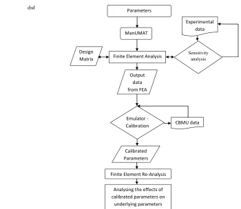
Figure 1 shows a methodology combining FEM and Statistical Modelling (SM) to estimate improved parameters in Finite Element (FE) models for irradiated and oxidized graphite through a calibration of FE models to CBMU measurements, using a Bayesian emulator. Each step is discussed under their headings in the paper.
3
dsd Parameters
Sensitivity analysis
Finite Element Analysis ManUMAT
Design Matrix
Output data from FEA
Emulator - Calibration
Calibrated Parameters
Finite Element Re-Analysis
Experimental data
CBMU data
Analysing the effects of calibrated parameters on
underlying parameters
Figure 1. Methodology for the calibration of parameters
FINITE ELEMENT MODELING
Mesh and modeling technique
4
(a) (b)
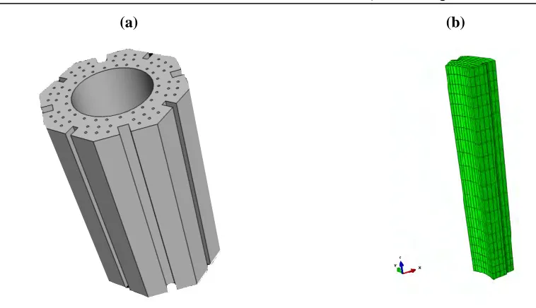
Figure 2. Geometrical model (a) and FE meshed octant model (b) of an AGR nuclear graphite brick.
Loadings
In the finite element analyses, the temporal and spatial distributions of the loads for the brick were used in the form of field variables that describe the distributions of fast neutron fluence, irradiation temperature, and weight loss. Examples of the field variables are shown in Figure 3.
(a) (b) (c)
5
Baseline parameters
The ManUMAT subroutine is a combination of models originally developed at British Energy (2003) and the new models derived by Eason et al. (2005 & 2008). The standard inputs or baseline parameters for the ManUMAT and for the FEA of reactor, graphite components were obtained from the other ongoing research project within the BCN, British Energy (2003), MTR and other experimental means. Typical example of the baseline parameters are shown in Table 1.
Table 1: Example of baseline dimensional change parameters
Parameter Baseline value
Dimensional change coefficient A1 2.762
Dimensional change coefficient A4 0.965
Dimensional change weight loss term z 0.05
SENSITIVITY ANALYSIS
The model presented here starts with the step of sensitivity analysis. Empirical equations and FEM were used and the baseline parameters are varied and compared with the available experimental, MTR or CBMU data (whichever was appropriate). Here in this paper to show the concept, the dimensional change [Equation 1- Eason et al. (2005)] in the brick is compared with the experimentally measured data by varying dimensional change parameters (Table 2) (as an example). Each of these inputs was varied independently (and in some cases, combined as well) between perceived ‘realistic’ limits i.e. between the experimental data range. Those parameters were identified which caused a notable change in radial displacement which was greater than 0.02%. These were found to be of major importance i.e. greater than 0.05% which are dimensional change terms A1 and A4, and weight loss term z (Example is
shown in Figure 4). Once the parameters were identified, these were then used in the construction of design matrices for FE iterative runs.
DimChg=DRB3 [B1(DR-A4)2-B2] (1)
where, DR is a dose ratio, B2 and B3 are fitting functions and B1 is a dependent function of fitting
functions, initial dose ratio, irradiation temperature and dimensional change coefficients.
Table 2: Example of limits for sensitivity analysis
Parameter Maximum Minimum
Dimensional change coefficient A1 3.05 2.15
Dimensional change coefficient A4 1 0.89
6
A1 A4
Figure 4. Variation of dimensional change coefficients
DESIGN MATRIX
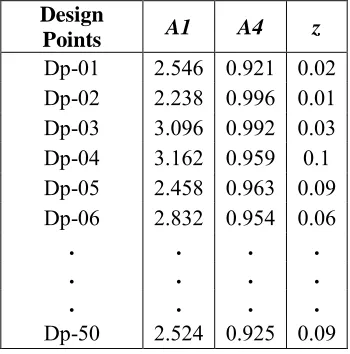
To get the input matrix for the emulation and calibration purpose, it is important to have enough data to cover the design space being investigated. For this purpose a design matrix was built using the identified parameters (from the previous step i.e. sensitivity analysis). The limits (Table 2) were then used to build a design matrix. In the current investigation a design matrix of 50 points was built (a typical example can be found in Table 3) and these were implemented into a set of FEA. Other parameters (which were not sensitive) were kept at their baseline values in the FEA.
Table 3: Typical example of design matrix for FEM
Design
Points A1 A4 z
Dp-01 2.546 0.921 0.02 Dp-02 2.238 0.996 0.01 Dp-03 3.096 0.992 0.03 Dp-04 3.162 0.959 0.1 Dp-05 2.458 0.963 0.09 Dp-06 2.832 0.954 0.06
. . . .
. . . .
. . . .
Dp-50 2.524 0.925 0.09
7
125 126 127 128 129 130 131 1320 5 10 15 20 25 30
B o re m id -h ei g h t a g er a g e ra d iu s (m m ) Time (years)
---Maximum Minimum CBMU Baseline
Figure 5. Examples of bore mid-height average radii from the design point FEA
EMULATION AND CALIBRATION
The Bayesian emulator used in this research was built in HSL (details are not presented in this paper) and is based on a Gaussian Process (GP) regression model. Emulator used as a substitute for the FEM and is designed in such a way that it helps in reducing the number of runs of FEM. This approximation technique is adopted to cover those design points which were not covered by FEM i.e. points which were not covered by the design matrix. Here in this research, the model links predictions of brick bore average radii at mid-height from the emulator to CBMU observations and fine tune discrepancies between predictions and observations and output the results at the best fit.
Calibration can be conducted for each layer as well as for a completed channel (multiple layers) using different themes. In this paper three themes were used, which are: (1) All three parameters could vary per layer, (2) All parameters are set same for the whole channel, (3) Two of the parameters (A1 and A4) remain common to all layers but the third (dimensional change weight loss term z) vary per layer. The
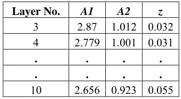
expectation was that the parameters would be common per reactor as there should only be scatter in the underlying behaviour and properties in the graphite per layer due to inhomogeneity in the material, batch differences etc. In the current example the output from the emulator deduced that by using theme 3 the calibration gives a better agreement with the CBMU data as compared to the theme 2 and to single layer calibrations. Typical examples of calibrated parameter are given in Tables 4.
Table 4. Example of calibrated parameters
Layer No. A1 A2 z
3 2.87 1.012 0.032 4 2.779 1.001 0.031
. . . .
. . . .
8
The main aim of this paper is to present the methodology devised, therefore, here the results are not discussed technically. The model presented here has provided some promising results including calibrated parameters which can be used to analyze other underlying parameters to study the behaviour of nuclear graphite under combined effect of both irradiation and radiolytic oxidation. The technique presented here is the first step towards the wide scope of BCN project.CONCLUSION
A model is devised using the combined finite element and Bayesian emulator approach. The model is applied to the investigation of dimensional changes of the graphite in both fast neutron irradiation and oxidizing environment. Application of this approach in the presented paper devised that, except the dimensional change parameters A1 (WG), A4 (WG) and the oxidation term z, the bore
mid-height average radius is insensitive to all other parameters. In future, the focus will be placed on determining the suitable matrix for stresses and ovality and conducting a similar combined finite element and statistical approach to study the ovality and the stress behavior under oxidation environment. The work which is being conducted in BCN is the anticipation for the future prediction and may lead to the understanding of cracking behaviour of the brick bore and hence the key way root of the nuclear graphite.
ACKNOWLEDGEMENT
The authors wish to thank the Office for Nuclear Regulation (Health & Safety Executive), UK for sponsoring this project.
DISCLAIMER
Any views or opinions presented are those of the authors and do not necessarily represent those of the sponsor.
REFERENCES
British Energy Generation Ltd, (2003). "Compendium of CAGR core and sleeve data and methods,"
British Energy Generation Limited, CSDMC, Paper 28.
Chang, S.J. (1974). "Viscoelastic analysis of irradiated graphite with variable creep coefficient," Journal of Nuclear Engineering and Design, 30, 286-292.
Eason E, Hall G, Marsden B, Heys G. (2005), " Development of a Model of Dimensional Change in AGR Graphites irradiated in Inert Environments," Conference on Ageing Management of Graphite Reactor Cores, Wales, 43-45.
Eason E, Hall G, Marsden B, Heys G. (2008),"Development of a Youngs modulus model for Gilsocarbon graphites irradiated in inert environments," Journal of Nuclear Materials, 381(1-2): 145-151.
Kelly, B.T. (1982). "Graphite - The most fascinating nuclear material," Carbon, 20(1), 3-11.
Neighbour, G.B. (2001). "Modelling dimensional change with radiolytic oxidation in AGR moderator graphite, Ageing studies and lifetime extension of materials," Chapter 2, Part 4, Springer, US, 419-427.
Tsang, D.K and Marsden, B.J. (2006), "The development of a stress analysis code for nuclear graphite components in gas-cooled reactors," Journal of Nuclear Materials, 350, 208–220.