real world solutions for storage networking
1·888·AT·VIXEL / www.vixel.com
Vixel HQ / 11911 North Creek Parkway South / Bothell, WA 98011 / USA
tel 425 806 5509 / fax 425 806 4050
Vixel Europe / P.O. Box 261 / Great Missenden / England / HP16 0XX
tel 011 44 1494 890666 / fax 011 44 1494 863331
Vixel Asia Pacific / 11911 North Creek Parkway S / Bothell, WA 98011 / USA
tel 626 858 2430 / fax 626 915 0759
Managed Storage Switch
InSpeed Model 335
O
N
&
C
O
N
FI
GU
RA
TIO
N
guide
without the written consent of Vixel Corporation.
Information furnished by Vixel Corporation is believed to be accurate and reliable. However, no responsibility is assumed by Vixel Corporation for its use; or for any infringements of patents of other rights of third parties which may result from its use. No license is granted by implication or otherwise under any patent or patent rights of Vixel Corporation.
Vixel and InSpeed™ are registered trademarks of Vixel Corporation. All other brand or product names referenced herein are trademarks or registered trademarks of their respective companies or organizations.
Vixel Corporation provides this manual “as is,” without any warranty of any kind, either expressed or implied, including but not limited to the implied warranties of merchantability or fitness for a particular purpose. Vixel Corporation may make improvements and changes to the product described in this manual at any time and without any notice. Vixel Corporation assumes no responsibility for its use, nor for any infringements of patents or other rights of third parties that may result. Periodic changes are made to information contained herein; although these changes will be incorporated into new editions of this manual, Vixel Corporation disclaims any undertaking to give notice of such changes.
Table of Contents
1
Introduction... 1
2
Installation... 3
3
Management ... 11
4
Technical Reference... 54
A p p e n d i x e s . . . 57
A
Specifications ... 58
B
CLI Console Commands ... 60
C
Event Messages ... 63
D
Loop ID—AL_PA Cross References ... 67
E
Glossary... 68
Introduction
A bo ut T h i s G u i de
This guide is designed to provide the user with the necessary information to install the Vixel Model 335 Switch and associated Small Form-Factor Pluggable Transceivers (SFPs) for use in Fibre Channel applications in typical Storage Area Networks (SANs).
O v e rv i e w
The twelve-port switch provide 1 or 2 Gigabit per second (Gb/s) Fibre Channel support and the flexibility of SFP-based design in a 1U full-rack size. The switch is designed as a twelve-port central interconnect for Fibre Channel applications and supports the ANSI FC-AL standard.
Note: Nodes include host computers, servers, and storage arrays.
Devices are connected to the switch through Small Form-factor Pluggables (SFPs) transceivers and cables. Each attached node has 1 or 2 Gigabit-per-second (Gb/s) of available bandwidth; however, all ports must be set to the same speed. Ports with no inserted SFPs or with inoperative nodes are bypassed. The switch’s LED indicators provide status information to service personnel to indicate whether the port is active or bypassed.
F e a t u r es
The switch incorporates the following features: • InSpeed™ Te chn ology
• Operating speeds of either 1.0625 or 2.125 Gb/s.
• Standard 1U size for easy installation into standard rack or placement on a tabletop. • Twelve SFP ports for total cabling flexibility and scalability.
• Management through the switch’s integrated web server or command line interface (CLI).
• 10BaseT Ethernet and RS-232 Serial ports on the switch. • Switching and non-switching operating modes.
• System and port status LED indicators
• Auto-sensing, universal power supply supporting 100 to 250 VAC and 50 or 60 Hz. About This Guide 1
Overview 1
Features 1
Fibre Channel-Arbitrated Loop 2
InSpeed™ Technology 2
F i b r e C h a n n e l - A r b i t ra t e d L o o p
The Fibre Channel-Arbitrated Loop (FC-AL) is an ANSI standard (X3T11) designed to provide shared bandwidth over low-cost media. Early adopters primarily use the SCSI protocol transported over Fibre Channel for distributed server and storage cluster applications. The switch is a central point of interconnect designed to maintain a fault-tolerant physical loop topology.
I n S p e e d ™ Te c h n o l o g y
Vixel’s InSpeed™ technology enables the switch’s router to properly utilize the switch core in sending data from one port to another. This process allows for multiple, simultaneous conversations between ports — effectively multiplying bandwidth. Using an advanced switching architecture that couples a non-blocking crossbar switch with unique port logic and per-port SERDES', the InSpeed™ technology creates the industry’s highest-density Fibre Channel switch.
This technology provides the same performance as switches that support FC-SW2, while solving the latency problems associated with large FC-AL loops. During initialization, InSpeed™ connects all devices together in a standard FC-AL2 loop. Upon completion of the initialization process, InSpeed™ transitions to switching mode. When arbitration is attempted, InSpeed™ analyzes connections and routes traffic directly to the destination port.
Installation
U n p a c k i n g t h e S w i t c h
To unpack the switch:
1. Inspect the outer shipping container for any damage that may have occurred in shipping and report any sign of damage to the appropriate shipping agency. 2. Remove the switch from the shipping container; save the shipping container, foam,
and anti-static bags—returning the switch in any other container or packing material may void its warranty.
3. Inspect the switch thoroughly. (If any signs of damage are seen, notify your sales representative and/or the shipping agency.)
I n s t al l i n g t h e S w i t c h
You can install the switch into an equipment rack or place it on a desktop.
Note: For information on environmental
requirements, see
“Operating Conditions” on page 59.
To mount the switch in a rack, consult the installation documentation that shipped with the rack-mounting kit (ordered separately).
To place the switch on a desktop:
1. Turn the switch upside down so the case bottom is facing up.
2. Install a self-adhesive pad on each corner of the switch (prevents surface damage) at the corner marks on the switch underside.
3. Turn the switch right side up so the case bottom is facing down. Note: The plug on the
power cord is intended to serve as the disconnect device. To cycle power to the switch, remove and reconnect the switch’s power cord.
4. Attach one end of the switch’s power cord to the switch’s power inlet socket and the other end to a properly earthed receptacle (outlet).
5. Insert the power cord firmly into the power inlet socket.
The switch is now powered on. The switch automatically executes a Power-On Self Test (POST) and its LEDs display the test results (for a description of the POST sequence, see “Performing a Power On Systems Test” on page 4).
Unpacking the Switch 3
Installing the Switch 3
Using Small Form-Factor Pluggable (SFP) Transceivers 4
Performing a Power On Systems Test 4
Setting Up the Switch 5
Attaching Devices 5
Understanding the Switch’s LEDs 6
U s i n g S m a l l F o rm - F a c t o r P l u g g a b l e (S F P ) Tr a n s c e i v e rs
The switch supports any SFP module that complies with the SFP specification as produced by MSA consortium.
The SFPs are “hot-pluggable” into the switch which allows host computers, servers and storage modules to be added dynamically without requiring power removal from the switch or any connected devices.
Small Form-Factor Pluggable (SFP) Installation
An SFP plugged into the switch will be automatically inserted when it is ready to begin initialization.
To insert an SFP, slide the SFP into the port, ensuring the correct orientation, until the latch clicks into place.
Small Form-Factor Pluggable (SFP) Removal
Removal of SFPs from a switch port causes the automatic bypass of that port. The remaining switch ports continue to operate normally with no degradation of system performance.
To extract an SFP, determine first what kind of extraction mechanism the SFP has.
Note: Most SFPs require you to remove the cable prior to removing the SFP from the port.
If the SFP has a removal tag, pull the removal tag to extract the SFP from the port.
If the SFP has a small plastic slider on the bottom side under the optical connector,
simultaneously push in the slider and pull out the SFP.
If the SFP has a bale (small metal clasp), unlatch the bale and pull on it to extract
the SFP from the port.
Pe r fo rm i n g a P o w e r O n S y s te m s Te s t
When the switch is powered on, the switch runs through Power-On Self Test (POST) diagnostics to verify the fundamental integrity of the switch box.
1. All switch LEDs turn on (LEDs illuminate) for approximately two seconds during power on, then all LEDs—except for the Power LED—turn off (LEDs extinguish).
S e tt i n g U p t h e S w i tc h
Before the switch can establish communication with your network, its IP Address needs to be changed from its default value.
To set the IP Address:
1. Attach one end of an RS-232 null modem cable to the serial port on the workstation; attach the other end to the RS-232 port on the switch.
2. For Unix workstations, type the following command at a Unix prompt (where
SerialPortDevicePath is the filepath to the serial port used for connection):
cu -s 19200 -b 8 -1 SerialPortDevicePath
For Windows® platforms, open a terminal session through a terminal emulation
program (such as HyperTerminal) with the appropriate serial port (for example, COM1) and the following serial port parameters:
• Bits per second: 19200 • Data bits: 8
• Parity: None • Stop bits: 1
• Flow control: Xon/Xoff
You are now connected to the CLI.
3. To log onto the CLI, type li at the prompt, then type the password (the default pass-word is password).
4. To change the switch’s IP parameters, type co and then type 1 to change the switch’s IP address.
5. If you want to change the switch’s netmask and default gateway, type 2 and 3, respectively.
6. Type 5 to save changes and reset the management agent. (The management agent must be reset for the change to take affect.)
7. To log off the CLI, type lo at the prompt.
For more information on configuring the switch through the CLI, see “Using the Command Line Interface (CLI)” on page 36.
A t ta c hi n g D e v i c e s
To attach devices to the switch:
1. Insert an active (that is, Ethernet hub- or Ethernet switch-attached) Ethernet RJ-45 twisted pair cable into the switch’s 10BaseT management port and ensure that the Enet Act (Green) LED is on (LED illuminates).
Note: You can attach cables to SFPs before or after SFP insertion (the switch bypasses ports that do not have attached cables).
2. Remove dust covers or plugs from the SFPs, if provided. 3. For each device:
a. Attach a cable to the device.
CAUTION: Forcing an SFP into a port may damage the SFP and/or port.
Note: FC-AL compatible nodes must perform initialization procedures upon power-up in order to function properly. It is the responsibility of the Fibre Channel driver software on FC-AL nodes to perform the initialization or re-initialization (depending on its prior state of operation).
4. Make sure the switch and any other connected switches or hubs are powered on. 5. Power on the storage devices (such as JBODs and RAIDs), then power on the hosts.
The network initializes.
6. Check all port LEDs. For more information on Port LED status, See “Port LEDs” on page 7.
7. Check the green Switch Op (Switch Operational) LED. If the Switch Op LED is lit, all zones with inserted devices are operational. If the Switch Op LED is blinking in a multiple zone configuration, one or more zones are operational while others are not. If the Switch Op LED is off, no operational zones exist or no devices are attached. Note: Improper initialization could be the result of a defective or inoperative host bus adapter card or device. Consult the vendor’s documentation for adapter diagnos-tic procedures.
U nd e rs t a nd i ng t he S w i tch ’s L E D s
You can check the system and port status through the Light-Emitting Diodes (LEDs) on the switch.
The switch utilizes two sets of LEDs to indicate switch and port status:
1. System LEDs – Six separate LEDs that indicate the status of the switch separate from the Port LEDs.
2. Port LEDs – Two LEDs per switch port that indicate status of that specific port
Figure 2-1. Switch features diagram
Power On
When powering on the switch, all LEDs turn on for two seconds and then off for two seconds except for the Power LED, which remains lit while the switch is powered.
System LEDs
There are six LEDs that indicate the status of the switch, independent of the port LEDs:
Figure 2-2. System LEDs
Switch Fault
Switch Operational
Switch Speed
Port LEDs
Port LEDs indicate the current status of the particular port.The switch uses two port LEDs: SFP Status and Port Bypassed/Port Activity. The Port Bypassed and Port Activity LEDs share the same yellow/green LED.
Figure 2-3. Port LEDs
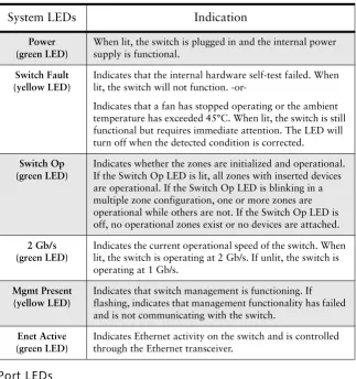
System LEDs
Indication
Power (green LED)
When lit, the switch is plugged in and the internal power supply is functional.
Switch Fault (yellow LED)
Indicates that the internal hardware self-test failed. When lit, the switch will not function.
-or-Indicates that a fan has stopped operating or the ambient temperature has exceeded 45°C. When lit, the switch is still functional but requires immediate attention. The LED will turn off when the detected condition is corrected.
Switch Op (green LED)
Indicates whether the zones are initialized and operational. If the Switch Op LED is lit, all zones with inserted devices are operational. If the Switch Op LED is blinking in a multiple zone configuration, one or more zones are operational while others are not. If the Switch Op LED is off, no operational zones exist or no devices are attached.
2 Gb/s (green LED)
Indicates the current operational speed of the switch. When lit, the switch is operating at 2 Gb/s. If unlit, the switch is operating at 1 Gb/s.
Mgmt Present (yellow LED)
Indicates that switch management is functioning. If flashing, indicates that management functionality has failed and is not communicating with the switch.
Enet Active (green LED)
An explanation of the Port LED indicators is listed below:
SFP
Status
LED
Port
Bypassed/
Activity
LED
Indication
Off Off Normal status of operation for ports in which SFPs are not installed.
The port will be in the bypass state, which precludes the port from participating in the network.
On Off Normal operation. Port and device are operational.
On On
(Yellow)
Bypass. The port is non-operational due to loss of signal, poor signal integrity, or the attached node is sending LIP(F8,xx).
This is the normal status condition when the SFP is present but not attached to a FC-AL node, or if it is only attached to a cable assembly with nothing attached at the opposite end. Replacing such a port (or replugging the same port twice) is considered to be a configuration change, which should initiate the Loop Initialization Procedure by the attached device.
Off On
(Yellow)
Tx Fault. The port is non-operational due to an SFP transmitter fault or improperly-seated SFP.
Off Blinking
(Yellow)
The port is being manually controlled by a management entity.
Blinking Blinking (Yellow)
A management entity is forcing a port beacon to locate a particular port on the switch.
On On
(Green)
C a s ca d i ng S w i t c h e s
Cascading allows you to connect two or more switches together to increase the number of ports and available devices. The switch allows you to link up to 12 switches. Multiple cascades between switches provide link and communication redundancy. You may have up to three cascades between a pair of switches.
Note: The primary switch disables the transceivers on all redundant connections, so only the primary cascade is enabled. If the primary cascade goes down, another cascade is then enabled.
The primary cascade is determined by the order of discovery in the primary switch (the switch with the lower Serial Number). If the primary cascade fails in either switch, an automatic failover occurs on one of the other cascades.
Figure 2-4. Cascading Switches in Overlapping Zones
Cascading with Non-Overlapping Zones
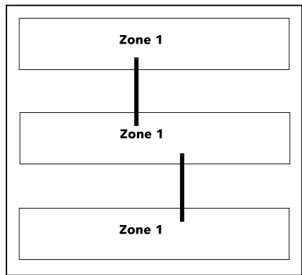
There are certain cascade restrictions when using non-overlapping zones. The following examples outline these restrictions.
1. You may only have multiple cascades between switches in Zone 1.
Figure 2-5. ACCEPTABLE: Multiple Cascades in Zone 1 Zone 1
Zone 1
Zone 1
Zone 1 Zones 2-12
2. You may not have multiple cascades in Zones 2-12.
Figure 2-6. NOT ACCEPTABLE: Multiple cascades in Zones 2-12
3. You may have a single cascade in Zones 2-12 only.
Figure 2-7. ACCEPTABLE: Single Cascade in Zones 2-12 Only
4. You may not create a cascade in Zone 1 and another cascade in Zones 2-12.
Figure 2-8. NOT ACCEPTABLE: Cascades in Zone 1 and Zones 2-12
For more information on zoning, see “Zone Settings” on page 31.
Zone 1 Zones 2-12
Zone 1 Zones 2-12
Zone 1 Zones 2-12
Zone 1 Zones 2-12
Zone 1 Zones 2-12
Management
O v e rv i e w
The switch utilizes both a Web Manager interface and a Command Line Interface (CLI) to manage the switch. You can change the switch’s device identification, upgrade firmware, configure switch settings and policies, define severity levels for event messages, and configure zoning.
U s i n g t he We b M a n a g e r
The Web Manager enables you to manage and monitor a switch from any network-connected computer. (Supported browsers are Netscape Navigator 4.7 or higher and Microsoft Internet Explorer 5.0 or higher. The browser needs to be Javascript-enabled.) With the Web Manager, you have the added benefits of easy navigation, simultaneous configuration of multiple ports, and named—rather than enumerated values within complex tables.
Connecting to the Web Manager
For a workstation to connect to the Web Manager, it must have access to the network on which the switch is connected.
If you need to verify the switch’s IP address, log into the switch’s command line interface through a serial link (see “Connecting to the CLI” on page 36).
To connect to the Web Manager:
1. Make sure the switch is connected to your network.
2. On a network-connected computer, open a web browser (such as Netscape Navigator or Microsoft Internet Explorer); in the URL text box, enter the switch’s address (DNS name or IP Address).
Overview 11
Using the Web Manager 11
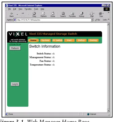
Figure 3-1. Web Manager Home Page
The Web Manager for the selected switch appears, and monitoring is available. Configuration links and elements are visible only when you are logged in, as noted in “Using the Command Line Interface (CLI)” on page 36.
Note: The web browser’s appearance and
information depends on the switch’s active firmware version and may change without notice in subsequent firmware versions.
To display updated information while using the Web Manager, click the Refresh button on the page.
Navigation
To ensure that refreshed information is displayed, use the navigation links and buttons (such as “Back”) that are on the Web Manager web pages. (The browser’s “Back” and “Next” buttons usually display cached copies, which do not reflect the current information on the switch.)
The highlighted button at the top of the page indicates your current location.
Logging On and Off
Note: For security, pass-words (for accessing the Web Manager & CLI) can only be changed through a serial connection to the switch.
The Web Manager does not require log-on unless you want to modify the switch’s parameters or configuration (such as zone or policy configurations).
To log on to the Web Manager, click Log In, type the correct password (the default is password), and click Log On.
To log out of the Web Manager, click Log Out or close the browser window.
Configuring the Switch
A quick list of frequent configuration tasks and their locations is shown here. More detailed information on each configuration task follows the table. Once you reach the location, you may need to click Change Settings and/or other links or buttons before configuration parameters are available for changing.
Note: To configure switch settings, you must be logged into the Web Manager.
General switch status is shown on the Home page (click Home). You can click the options at the top of the page to view additional information and configure the switch. These options are discussed in more detail on the following pages.
Resetting the Switch
Changes to certain switch settings require you to reset the switch for those changes to occur. You must be logged into the Web Manager to reset the switch.
To reset the switch, click Reset Switch on the Home page.
Configuration Task Location in Web Manager
Change the switch speed (See “Switch Speed” on page 16.)
System > Change Settings
Change device identification, contact, and location
(See “Switch Identification” on page 16.)
System > Change Settings
Upgrade firmware
(See “Firmware Settings” on page 18.)
System > Firmware
(click Load New Firmware Image)
Change the network settings (IP Address, Gateway, and Netmask)
(See “Network Settings” on page 15.)
System > Change Settings
Change the time settings (See “Time Settings” on page 17.)
System > Time > Change Time Settings
Configure zoning
(See “Zone Settings” on page 31.)
Zoning
View & download event log (See “Event Log Messages” on page 19.)
System > Event Log
Reset switch
(See “Resetting the Switch” on page 13.)
Home (click Reset Switch)
View & update policies (See “Policy Settings” on page 29.)
System Information Settings
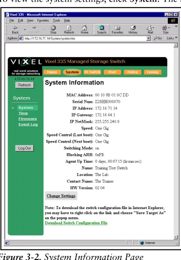
The System Informations page displays the switch’s parameters and general configuration settings.
To view the system settings, click System. The System Information page appears.
Figure 3-2. System Information Page
The displayed settings are listed below:
Setting Description
MAC Address A unique device address assigned to each switch at the
factory. Cannot be configured or modified.
Serial Num(ber) A unique identification number assigned to each switch at the
factory. Cannot be configured or modified.
IP Address The current IP Address for the switch.
IP Gateway The current Gateway address for the switch.
IP Netmask The current IP Netmask address for the switch.
Speed The current speed setting for the switch.
Speed Control (Last boot) The speed setting selected during the last switch power-up.
Speed Control (Next boot) The speed setting selected for the next switch power-up.
Switching Mode When "on", allows data to be sent directly to a specified port.
If "off", the data is sent to every port. Disabling Switching Mode may be necessary when passing data to legacy devices.
Blocking ARB When two ports start a communication session, the Blocking
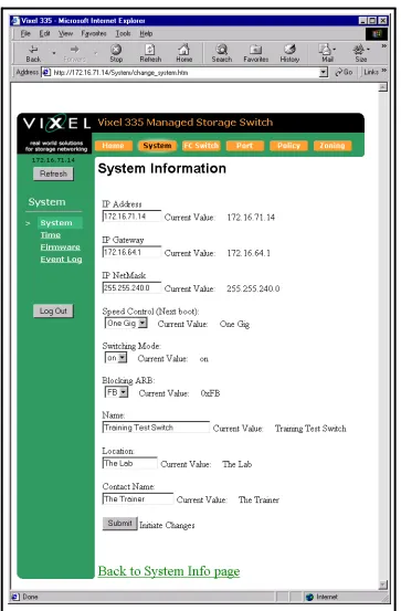
To modify the current settings, click Change Settings. The System Information page appears with the fields available for modification.
Figure 3-3. System Information (Change Settings) Page
Network Settings
You can change the switch’s network settings (IP Address, Gateway, and Netmask) through the Web Manager once the switch has established communications with the network.
Note: To change the network settings of a switch that is not yet communicating with your network, connect through a null modem serial cable and change the IP Address through the CLI. For further information, See “Using the Command Line Interface (CLI)” on page 36.
To view the current network settings, click System.
To change the switch’s network settings:
1. Click Change Settings.
2. Type the new setting (IP Address, Gateway, or Netmask) in the appropriate text box. 3. When finished, click Submit.
Agent Up Time The duration of time the switch has been operational.
Name The name of the switch.
Location The location where the switch resides.
Contact Name The person’s name to contact for switch issues.
HW Version The hardware version of the switch. Cannot be configured or
modified.
4. You must reset the switch for the new network settings to become active. To reset the switch in the Web Manager, click Home and then click Reset Switch. You may also reset the switch through the CLI. See “Resetting the Switch” on page 51.
Switch Speed
The switch is set to 2.125 Gb/s as the factory default switch speed.
To view the current switch speed, click System.
To change the switch speed:
1. Click Change Settings.
2. From the Speed Control (Next boot) drop-down box, select the desired speed.
3. Click Submit. The next time you reset the switch the new switch speed will be applied.
Switching Mode
When enabled, switching mode allows data to be sent directly to a specified port. If switching mode is disabled, the switch sends data to every port. Disabling Switching Mode may be necessary when passing data to legacy devices.
To view the current mode, click System.
To change the switching mode:
1. Click Change Settings.
2. Select either "on" or "off" from the Switching Mode drop-down box. 3. Click Submit.
Blocking ARB
Note: This setting should not be modified unless directed to do so by Vixel Customer Service.
When two ports start a communication session, the Blocking ARB is sent to any other ports trying to communicate with those specific ports until their connection is terminated.
To view the current Blocking ARB value, click System.
Switch Identification
You may modify the switch’s name, location, or contact name.
To view the current information, click System. To change the switch identification:
1. Click Change Settings.
2. Enter the new value in the appropriate text box. 3. When finished, click Submit.
Setting Description
One Gig Set switch speed to 1.0625 Gb/s.
Downloading the Switch Configuration
You can download the current switch configuration to the Web Manager. The configuration file displays in text format.
To download the switch configuration, click Download Switch Configuration File. A text file appears displaying the current switch configuration. You can save or print the information.
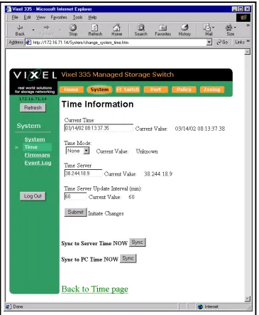
Time Settings
To view the current time settings, click System and then click Time. The Time Information page appears.
Figure 3-4. Time Information Page
To change the time settings, click Change Time Settings. The Time Information page appears with the fields available for modification.
To change the Time Mode:
1. From the Time Mode drop-down box, select the desired time setting.
2. Click Submit.
To use a time server:
1. Select Server in the Time Mode drop-down box.
2. Enter the IP Address for the time server in the Time Server text box.
3. Enter the desired update interval in minutes in the Time Server Update Interval (min) text box.
4. Click Sync to Server Time to immediately synchronize the server time to the time server at the designated IP Address.
5. Click Submit.
To set the time setting to the computer connected to the switch, click the Sync to PC Time Now Sync button and then click Submit.
Note: Clicking Back on the browser tool bar may not update settings due to web browser caching pages in memory.
To view the new time settings, click Back to Time page.
Firmware Settings
The Firmware page displays information on the current firmware version, the alternate firmware version, and the version of the software that loads the firmware image on boot up.
To view the current firmware settings:
1. Click System. The System Information page appears. 2. Click Firmware. The Firmware Information page appears.
Figure 3-6. Firmware Information Page
Setting Description
none The switch does not set the time.
Server The switch receives the time from a time server via
Ethernet.
To change the firmware settings:
1. Click Change Firmware Settings.
2. Click Switch Image for execution on next boot to swap the current firmware image and the alternate firmware image. The page informs you of which firmware image will be loaded on the next boot cycle.
3. Click Back to Firmware page to return to the Firmware page.
4. Review the Firmware Information display to ensure that the proper firmware image will be loaded on the next boot cycle.
To upgrade the firmware:
1. Click Load New Firmware Image.
2. Enter the directory path to the specific file in the text box, or click Browse to navigate to the appropriate file.
3. Click Load Image to download the firmware image.
4. Once the new image is downloaded, click Back to Firmware page to return to the Firmware page.
5. Review the Firmware Information display to ensure that the proper firmware image will be loaded on the next boot cycle.
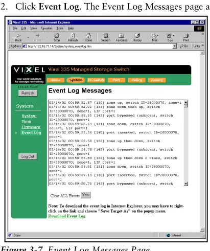
Event Log Messages
The Event Log Messages page displays a list of event log messages generated by the switch. The event log holds approximately 500 messages at a time. For a complete list of event messages, see EVENT MESSAGES(APPENDIX C) on page 63.
To view the event log:
1. Click System. The System Information page appears. 2. Click Event Log. The Event Log Messages page appears.
Figure 3-7. Event Log Messages Page
To save the event log messages:
1. Click Download Event Log. 2. Click OK to save the file to the disk.
FC Switch Information
The FC Switch Information page displays the switch view by ports. Each port displays the zone, utilization percentage, and associated ALPA(s). You can identify all ports in a specific zone by highlighting that zone.
To view the switch settings, click FC Switch. The FC Switch Information page appears.
Figure 3-8. FC Switch Information Page
The displayed settings are listed below:
To highlight a specific zone, click the Highlight Zone drop-down box and select the desired zone. The highlighted zone displays in color.
Setting Description
Port number The port number on the switch.
Zone number The zone number to which the port is assigned.
Utilization percentage Measures the amount of traffic that is flowing through the
port.
ALPA(s) The Arbitrated Loop Physical Address for each device
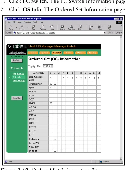
OS Information
The Ordered Sets Information page displays the Ordered Sets that are being transmitted on the switch by their associated port number.
To view the Ordered Sets Information page:
1. Click FC Switch. The FC Switch Information page appears. 2. Click OS Info. The Ordered Set Information page.
Figure 3-10. Ordered Set Information Page
If there is a connection, then the Ordered Set transmission information for that connection is depicted by an "X".
A list of the Ordered Sets and their indications follows:
Detection Indication
Non-Overlap Zone Displays the zone for which the port is configured.
Transceiver Displays the status of the inserted transceiver in the port.
Sync A stable signal has been detected and IDLEs transmitted.
Match The ordered set or pattern selected under the Match area has
been detected.
EOF An End-of-Frame (EOF) delimiter has been detected; frames are
present on the loop. (An EOF immediately follows the CRC of a frame and signals the frame’s end.)
SOF A Start-of-Frame (SOF) delimiter has been detected; frames are
present on the loop.
IDLE Sequences of IDLEs are being transmitted to maintain link
activity; no other data is being transmitted.
ARBff ARB(FF)s are being transmitted to maintain link activity; no
RRDY The receiving node on this port has sent an R_RDY signal, indicating that it is ready for a frame to be transmitted over the link.
CLS The port is attempting to begin the process of closing the current
loop circuit.
OPN The port is attempting to open communications with another
port on the loop. Note: As is the case with some ordered sets, an OPN may not go all the way around the loop, instead stopping at its destination.
LIP F8 A non-switching port has detected a loop failure on its receive
input, is notifying other ports, and is determining whether the loop is still operational.
Some events that could cause the port to detect loop failure follow:
• A device in the loop has failed.
• A device in the loop has been powered off.
• The physical connection between the transmitter and receiver is broken.
• Activating the port bypass circuit does not typically result in a loop failure.
LIP F7 A loop port is in the non-participating mode and is attempting
to win arbitration and begin initialization, possibly because the port was reset or is powering up. Sometimes the port is sending this sequence to another, hot-cascaded switch like a new initiator being inserted in the loop.
LIP A Loop Initialization Primitive (LIP) sequence has been detected
and action has been taken.
Unknown The switch can not determine what is being transmitted.
InvTxWd An invalid transmit word has been detected.
CRC Err A Frame CRC error has been detected.
To highlight a specific zone, click the Highlight Zone drop-down box and select the desired zone. The highlighted zone displays in color.
Figure 3-11. Ordered Set Information Page with Highlighted Zones
Port Usage Information
The Received Port Utilization page displays the ports and enables you to view the utilization percentages to determine which ports are busy.
To view the Received Port Utilization page:
1. Click FC Switch. The FC Switch Information page appears. 2. Click Port Usage. The Received Port Utilization page appears.
The Utilization Percentages values are:
The sample period, average windows size, and peak/low window size values are also displayed.
To highlight a specific zone to view traffic patterns, click the Highlight Zone drop-down box and select the desired zone. The highlighted zone displays in color.
Figure 3-13. Received Port Utilization Page with Highlighted Zones
To change the Port Usage settings:
1. Click Change Settings. The Received Port Utilization page appears with fields available for modification.
Figure 3-14. Received Port Utilization (Change Settings) Page
Value Description
Average % The average percentage data for the port in the zone over a period of Average
Window Size seconds.
Peak % The Peak data communication rate usage for the port
3. Click Submit to accept the changes.
4. Click Back to Port Usage to view the new settings.
Port Settings
The Port Information page displays the port status for each port on the switch.
To view the port settings, click Port. The Port Information page appears.
Figure 3-15. Port Information Page
The displayed settings are listed below:
Setting Description
Port The actual port on the switch.
Transceiver The type of transceiver inserted in the port.
Trcvr LED If a transceiver is inserted properly, the LED is on.
Fault LED The port is bypassed due to a problem detected by either the
transceiver’s transmit logic or the SFP transceiver itself. Transceiver problems include unconnected fiber, remote node not transmitting, LIP(F8), or a faulty transceiver.
State The current state of the selected port.
TX The state of the transmitter on the selected port.
Inserts The number of times a transceiver has been inserted into the
port since the last switch reset.
Freq The port locked in on the communicating frequency for which
the switch is configured.
Zone The zone in which the port is located.
Cascade Mode Displays the cascade mode for the specified port.
To highlight a specific zone, click the Highlight Zone drop-down box and select the desired zone. The highlighted zone displays in color.
Figure 3-16. Port Information Page with Highlighted Zones
To view information on a transceiver connected to a port, click serial mod def in the transceiver column. The specific transceiver’s information displays to the right of the current switch information.
To modify the port cascade settings:
1. Click Change Port Cascade Settings. The Cascade Information page appears.
Figure 3-18. Cascade Information Page
2. On this page, you can view the port settings, highlight a specific zone, or change the port cascade mode.
3. Select the port to modify by clicking the Cascade Mode drop-down box for the specific port.
4. Select the port cascade mode, which configures the port’s operation in the switch. The different port cascade modes are:
Mode Description
auto This setting automatically configures the connection type based on
information sent by other InSpeed switches. The default setting is Auto for InSpeed-based managed switches.
none The port is disabled.
tree A port that allows arbitration fairness to other cascaded
InSpeed-based switches or ports connected to end devices. If the port is a tree port then the ARB (Arbitrate) is sent down the port and, when the ARB is received back at the ASIC, a connection is made between the source and destination ports. All ports are viewed as 100% FC_AL compliant.
string A specially pre-allocated port designed to maintain fairness when
two or more InSpeed-based storage switches are serially cascaded. When the destination port is a string and an OPN is received on the ASIC, an ARB is transmitted throughout the total string cascade loop to alert all devices to enforce the Loop fairness rules. Therefore, if two devices try to ARB for the loop at the same time, the higher Priority AL_PA will win the cascade first, the lower priority one will follow.
Note: There must be two string ports on a zone. The port is
5. After making changes, click Submit to accept the changes.
To highlight a specific zone, click the Highlight Zone drop-down box and select the desired zone. The highlighted zone displays in color.
Policy Settings
Policies define switch operation and determine how the switch handles error recovery. The Policies page displays the switch policies that are enabled or disabled.
To view the policy settings, click Policy. The Policies page appears.
Figure 3-20. Policies Page
The displayed settings are listed below:
Switch Policy Description
Smart Insertion When this policy is enabled, the switch LIPs on the insert of a new
port and waits for LIP(f7)s to return prior to insertion. Also ensures that data meets the requirements of Fibre Channel Arbitrated Loop (FC-AL) and allows sub-policies to be enabled.
Auto Cascade* When a port is connected to another Vixel Model 335 switch, the
switch will automatically configure the port to the connected device type.
Bad Zone recovery* The switch reinitializes the zone and will bypass zone ports that are
down. The switch will bypass all ports when:
• Zone 1 has a least one transceiver with a signal and the port is in
auto mode.
• No ports in the zone are in forced insert mode (Port Control).
• The zone state is down.
No Data Recovery* The switch will bypass a port if no K characters (Ordered Sets) are
detected for 100 usecs. The switch will try to reinsert the port upon detection of valid K characters.
LIP(F8) Recovery* The switch will bypass a port if a LIP(F8) is received. The switch will
try to reinsert the port when no more LIP (F8)s are received.
LIP on Port Bypass* When a port is bypassed, it issues LIP(F7)s to other zone members.
Bypass on Bad OS Threshold*
When a port exceeds the threshold of Ordered Set errors within ten seconds, the switch bypasses the port. Note: The threshold can be
adjusted. (224 – 1, the maximum expected error rate is one error
To update the switch’s policies:
1. Click Change Settings on the Policy page. The Policies page appears with fields available for modification.
Figure 3-21. Policies (Change Settings) Page
2. You can select whether to enable or disable a specific policy, set thresholds on certain policies, and select specific ports for the LIP on Insertion and Port Test Before Insertion policies.
3. Once you have made your changes, click Update Policies to accept the changes. 4. Click Back to Policy Page to review the new settings.
Bypass on CRC Error Threshold*
When a port exceeds the threshold of frame CRC errors within ten seconds in Zone 1 and in switching mode, the switch bypasses the port. Note: The threshold can be adjusted.
Bypass on Clock Delta Error
When this policy is enabled, the switch compares the detected line clock through the frame and the number of fill words inserted or deleted versus the switch’s internal clock. If the derived clock delta is too high, the port is bypassed.
LIP on Insertion* When a port inserts into a zone, it issues LIP(F7)s to other zone
members.
Port Test Before Insertion*
Before allowing a port to insert into a zone, the port is monitored for proper Loop Port State Machine (LPSM) protocols. (At least one of the devices on the port must be a Loop Initialization Master (LIM) to follow these protocols.)
Zone Settings
The switch uses two types of port zoning: Overlapping and Non-Overlapping Zones.
With overlapping zoning, devices on one port are not allowed to see devices on another port, yet those same devices can both see a device on a third port.
Figure 3-22. Overlapping Zones
In Figure 3-22, Zone 1 includes ports 1, 3, and 4, while zone 2 includes ports 2, 4 and 5. Port 4 overlaps both zones. Devices on ports 1, 3, and 4 can see each other and devices on ports 2, 4, and 5 can see each other, but devices 1 and 3 cannot see devices 2 and 5. Devices on port 4 can see all the devices on ports 1, 2, 3, and 5.
Non-overlapping zoning enables the switch to be divided into separate environments, where each environment sustains a complete 127-device AL_PA space.
Figure 3-23. Non-overlapping Zones
In Figure 3-23, Zone 1 devices operate independently of devices in Zone 2. Non-overlapping zoning allows for true LIP isolation. If a LIP occurs in one non-Non-overlapping zone, it will not affect the operation or traffic occurring in a different zone.
To view the zoning information, click Zoning. The Zone Information page appears.
The Zone Information page displays the current zoning configuration, the ports in each zone, the zone state, the init count, and the time duration ("up time") for the zone. The displayed settings are listed below:
Overlapping Zones
Overlapping zoning can only be implemented in Zone 1 and the switch must be operating in switching mode. To participate in overlapping zoning, each port must have their cascade mode configured to "auto".
If the switch is operating using non-overlapping zoning, you can still configure overlapping zoning within the default zone. If a LIP occurs on any port in the default zone, it will affect every port in the default zone, regardless of any overlapping zone configurations. Overlapping zones do not support LIP isolation.
To view the overlapping zoning, click Overlapping. The Overlapping Zone 1 Information page appears.
Figure 3-25. Overlapping Zone 1 Information Page
Setting Description
Zone number The zone number on the switch (1-12).
Port number(s) The port numbers that are assigned to the specified zone.
Zone state The current state of the zone; either "up" or "down".
Init Count The number of times a zone has transitioned from an "down" state to
an "up" state.
To configure the overlapping ports:
1. Click Change Overlapping Zones. The Overlapping Zone 1 Information page appears with the ports available for modification.
Figure 3-26. Overlapping Zone 1 Information (Configuration) Page
2. Click the appropriate check box for the two ports.
If the check box is selected (checked), the two ports can communicate with one another. If the check box is empty (not checked), the two ports are blocked from communicating with one another.
3. Once you have configured the overlapping ports, click Update Overlapping Zoning to accept the changes.
To view the your changes, click Back to Overlapping. Blocked ports are displayed in red, while non-blocked ports are displayed in gray.
Non-Overlapping Zones
Note: Ports 11 and 12 can only be in Zone 1.
The non-overlapping zones feature enables you to assign each port on the switch to one of 12 available zones. Each zone is unique which allows for 6 separate zones to function on the same switch. With non-overlapping zoning enabled, each zone is totally
independent and LIPs on one zone do not affect the other zones.
The default zone for the switch is Zone 1. Ports 11 and 12 are always included in Zone 1.
Note: You can have simultaneous overlapping and non-overlapping zoning. Overlapping zoning operates in Zone 1 and non-overlapping zoning operates in Zones 2-12.
To view the non-overlapping zoning, click Non Overlapping. The Non Overlapping Zone Information page appears.
Figure 3-27. Non-Overlapping Zone Information Page
To modify the port configurations in the various zones:
1. Click Change Non Overlapping Zones. The Non Overlapping Zones Information page appears with the ports available for modification.
Figure 3-28. Non-Overlapping Zones Information (Configuration) Page
Note: Ports 11 and 12 are always in Zone 1.
2. Click the Zone drop-down box for the specific port and select the zone for which you want the port to be a member. The port can be in one of twelve zones. 3. Click Submit to accept the changes.
To highlight a specific zone, click the Highlight Zone drop-down box and select the desired zone. The highlighted zone displays in color.
Figure 3-29. Non-Overlapping Zones Information (Configuration) Page with
U s i n g t h e C o m m a n d L i n e I n te r fa c e (C L I )
The Command Line Interface (CLI) allows you to complete several switch management tasks over Ethernet through a telnet session or through a direct serial link. While both the CLI and Web Manager interfaces allow you to view switch information and configure switch settings, the CLI also allows you to enable or disable DHCP requests, change the CLI/Web Manager password, manage traps, and complete several other switch management functions.
Connecting to the CLI
Note: You may have up to 10 concurrent telnet sessions accessing the switch.
You can connect to the CLI over the telnet interface or the serial link interface.
To connect over Ethernet through telnet interface:
1. Make sure the Vixel Managed Switch is connected to an Ethernet network via the switch’s Ethernet connection and that the monitoring workstation can access this Ethernet network.
2. Make sure that you know the switch’s IP address before connecting to the CLI. (the default IP Address is 0.0.0.0)
3. At a command line prompt, type telnetIP (where IP is the switch’s IP address). You are now connected to the CLI and ready to log on.
To connect through a serial link:
1. Attach one end of an RS-232 null modem cable to the serial port on the workstation; attach the other end to the RS-232 port on the switch.
2. For Unix workstations, type the following command at a Unix prompt (where
SerialPortDevicePath is the filepath to the serial port used for connection): cu -s 19200 -b 8 -1 SerialPortDevicePath
3. For Windows® platforms, open a terminal session through a terminal emulation program (such as HyperTerminal) with the appropriate serial port (for example, COM1) and the following serial port parameters:
• Bits per second: 19200 • Data bits: 8
• Parity: None • Stop bits: 1
• Flow control: Xon/Xoff
You are now connected to the CLI and ready to log on.
Logging On and Off
To log onto the CLI (once connected as shown above), type li at the prompt, then type the password (the default password is password).
To log off the CLI, type lo at the prompt.
Configuring the Switch
The CLI enables you to configure the switch settings, policies, and zoning.
A list of frequent switch configuration tasks and their commands is shown here. Refer to the provided page number for more detailed information on each configuration task.
To view the complete list of available switch commands while using the CLI, type ? or h
at the prompt. For a complete listing of all CLI commands, see CLI CONSOLE
COMMANDS(APPENDIX B) on page 60.
Configuration Task CLI Command
Change the IP parameters
(See “Changing the Switch’s IP Parameters” on page 38.)
co
Change switch identification, contact, location, etc. (See “Configuring Switch Information” on page 38.)
si
Upgrade firmware
(See “Managing the Firmware” on page 39.)
fw
Add or delete a trap destination (through the Configuration menu)
(See “Configuring the Trap Destination Table” on page 41.)
ct
Changing the password pw
View switch management, policies, error thresholds, and other switch settings.
(See “Viewing Management, Policy, and Threshold Settings” on page 43.)
mc
Change the switching mode
(See “Changing the Switching Mode” on page 47.)
sw
Configure zoning
(See “Viewing and Understanding Zoning Information” on page 52.)
oz
(for overlapping zoning)
noz
(for non-overlapping zoning)
Reset switch
(See “Resetting the Switch” on page 13.)
rs
Reset switch to factory default settings
(See “Resetting the Switch to Factory Default Settings” on page 51.)
rc
View & modify port settings (See “Displaying Ports” on page 49.)
po
Change the switch speed
(See “Changing the Switch’s Operating Speed” on page 52.)
lsp
View the event log
(See “Viewing the Event Log” on page 51.)
Changing the Switch’s IP Parameters
To view the current switch configuration, type co at the prompt. The Configuration Menu appears:
Before the switch can establish communication with your network, its IP address needs to be changed from its default value.
To change the switch’s IP parameters:
1. Type the option number (1-4) of the desired setting. 2. Enter a new value for that setting.
3. Type 5 to save changes and reset the switch. (The switch must be reset for the change to take affect.)
Enabling or Disabling DHCP Requests
When DHCP is enabled, the switch sends a DHCP request for its correct IP parameters (address, subnet mask, and default gateway) during power on. If a DHCP server responds, the switch automatically changes its IP settings.
Note: The default setting for the DHCP option is "disabled".
If you want to enable DHCP, ensure that there is a DHCP server connected to the same subnet as the switch. (For instructions on setting the switch’s IP parameters through a DHCP server, see the server documentation.)
If DHCP is enabled and a DHCP server is not found, the DHCP request will fail and the switch’s IP parameters will be incorrect. You will then have to connect through the serial port using the CLI, disable the DHCP mode, and manually configure the switch parameters.
To enable automatic DHCP requests from the switch:
1. Type co, then type 4.
The DHCP status is toggled to either enable or disable and the current setting is displayed.
2. Type 5 to save changes and reset the switch. (The switch must be reset for the change to take affect.)
Configuring Switch Information
To change the switch name, location, or contact name, type si at the prompt. The System Information Menu appears:
To change the information:
1. Type the option number (1-3) of the desired setting.
CONFIGURATION MENU
ACTIVE VALUE SAVED VALUE NEW VALUE 1. IP Address 172.16.52.2 172.16.52.2
2. Netmask 255.255.240.0 255.255.240.0 3. Default Gateway 172.16.48.1 172.16.48.1 4. DHCP Disabled
5. Save changes and reset switch 6. Save changes and exit menu 7. Discard changes and exit menu
SYSTEM INFORMATION MENU
Managing the Firmware
To view the current firmware settings and a complete list of commands, type fw at the prompt. The Internal Firmware Versions list and Firmware Menu appear:
The Internal Firmware Versions list displays the current and alternate firmware loaded on the switch. The Boot firmware is installed during the manufacturing process and manages the loading of the current firmware on the switch during power-up. The Boot firmware cannot be configured or modified.
To select the alternate firmware version, type 2 at the prompt. A message appears informing you that the Alternate firmware version has been selected and will load on the next switch boot.
Downloading New Firmware
You can use either of the following available download methods for Windows; for Unix workstations, use the Ethernet (TFTP) method.
To download firmware from a binary file, type fw and choose the desired downloading method.
Ethernet (TFTP) Method (Menu Option 3)
Use the Ethernet (TFTP) method for Unix workstations (this method can also be used on Windows NT workstations).
Note: The “Destination:” message varies according to the active firmware image and the platform you are using. See Step 2.
1. Type: 3 at the prompt.
The following message appears.
2. For Windows:
• Use a command line to move to the directory containing the new firmware and type the following (where IPaddress is the switch’s IP address and filename is the name of the binary firmware file) and press Enter.
tftp -i IPaddress PUT filename ramdisk
Within a few seconds, the “Transfer successful” message appears. (If the message does not appear, verify that the file is good and repeat the transfer.)
3. For Unix workstations:
a. At a Unix prompt, type the following (where IPaddress is the switch’s IP address) and press Enter.
tftp IPaddress
b. Type the following and press Enter. binary
c. Type the following (where filename is the name of the binary firmware file) and press Enter.
put filename /ram
Internal Firmware Versions:
---CURRENT: V2.01 (build 79) Mar 23 2002 00:48:59 ALTERNATE: V2.00 (build 69) Feb 27 2002 17:30:42 BOOT: V1.01 (build 55) Nov 9 2001 11:11:23
FIRMWARE MENU 1. Show versions
2. Select alternate version 3. Load new firmware via Ethernet 4. Load new firmware via serial 5. Reboot
6. Exit menu
d. Type the following and press Enter. quit
4. In the terminal session window, type 1 to verify and store the new firmware. The following message appears.
Type fw, then type 1.
The active and alternate firmware versions are displayed.
5. If the “alternate version” is anything other than the firmware you just downloaded, verify that the file is good and repeat the download.
6. If you want to activate the alternate version (the newly downloaded firmware): a. Type 2 to select the alternate version for execution on the next boot cycle. b. Type 1 to verify that the following message is displayed under the firmware
versions: “Note: ALTERNATE selected for execution on next boot cycle.” (If this message is not displayed, repeat steps a and b to toggle back.)
c. Type 5 to reboot.
The management agent disconnects, reboots, and activates the downloaded firmware. The “Disconnecting and Rebooting” message appears.
The firmware is downloaded.
Serial Method (Menu Option 4)
The Serial method for downloading firmware is available for Windows only.
1. Ensure that the switch and workstation are connected through a serial null modem cable.
2. Type 4. Note: To cancel out of the
file transfer facility, press CTRL+X several times.
The file transfer facility appears.
3. Choose Send File from the Transfer pull-down menu in HyperTerminal. The Send File dialog box appears.
4. Type (or browse for) the filename, select “1K Xmodem” from the Protocol drop-down list, and click Send.
A status message appears.
5. If the status message says anything other than “File transfer completed,” perform the action recommended for the appropriate message shown below.
Clearing backup host filename.. Clearing backup host IP address.. Verifying file integrity.. Erasing flash memory.. Programming flash memory.. Verifying..
*PROGRAM LOAD SUCCESSFUL*
Message Action
6. Type fw, then type 1.
The active and alternate firmware versions are displayed.
7. If the “alternate version” is anything other than the firmware you just downloaded, verify that the file is good and repeat the download.
8. If you want to activate the alternate version (the newly downloaded firmware): a. Type 2 to select the alternate version for execution on the next boot cycle. b. Type 1 to verify that the following message is displayed under the firmware
versions: “Note: ALTERNATE selected for execution on next boot cycle.” (If this message is not displayed, repeat steps a and b to toggle back.)
c. Type 5 to reboot.
The management agent disconnects, reboots, and activates the downloaded firmware. The “Disconnecting and Rebooting” message appears.
The firmware is downloaded.
Configuring the Trap Destination Table
Simple Network Management Protocol (SNMP) uses traps to transmit information to other IP Addressable devices on the network.
To view the current Trap Destination settings and a complete list of commands, type: ct at the prompt. The Trap Destination Table Menu appears:
To create a trap destination:
1. Type 1 to create the new TRAP destination.
2. At the resulting IP address prompt, type the address of the workstation you would like the trap sent to.
3. At the resulting UDP Port prompt, type the number of the listening port (usually “162”).
The Edit Trap Destination Menu appears.
TRAP DESTINATION TABLE MENU
IP ADDRESS PORT SEVERITY COMMUNITY STATE
Event traps: <none> FcMgmt traps: <none>
1. Create new TRAP destination 2. Delete TRAP destination 3. Exit menu
EDIT TRAP DESTINATION MENU
ACTIVE VALUE NEW VALUE IP Address 172.16.52.2 172.16.52.2 Port 162 162 1. Community 'public' 'public' 2. Severity Warning Warning 3. State Inactive Inactive 4. Mode Event Event
4. If you want to edit any of the listed options, type the number corresponding to the desired option (community [password], severity, state, or mode) and follow the prompts.
5. Type 5 to save changes and exit.
The Trap Destination Table menu appears and displays your saved changes.
To edit a trap destination:
1. Enter the row number for the TRAP destination that you want to edit. The Edit Trap Destination Menu appears.
2. Type the number corresponding to the option (community [password], severity, state, or mode) you want to change and follow the prompts.
3. Type 5 to save changes and exit.
The Trap Destination Table menu appears and displays your saved changes.
To delete a trap destination:
1. Type 3 to select the Delete TRAP destination option. 2. Enter the row number that you want to delete.
The trap destination is deleted.
Option Description
Community Sets the community string to public or private. An SNMP server has a
"community string" which is like a password to get or set information. Most devices have a "public" community string, which enables read-only access to MIBs, as well as a "private" community string that enables you to read and set certain parameters via SNMP. The community strings are case-sensitive.
Options: public private
Severity Select the severity level at which the traps become operational. The default
severity level is Warning. Options:
0-Emergency 1-Alert 2-Critical 3-Error 4-Warning 5-Notice 6-Info 7-Debug 8-Mark
State The state menu choice enables the trap to become active or inactive.
Options:
1-Destroy – the trap will be deleted from the table once changes are saved. 2-Inactive – the trap is not operational.
3-Active – the trap sends messages to the host identified in the IP Address selection.
Mode Determines whether the traps are accessed through the Event interface, the
Fibre Alliance interface, or both. Options:
Changing the CLI/Web Password
Note: If you do not remember your password, call your customer service representative.
One password is used to access both the Web Manager and the Command Line Interface. You can change the password through the Command Line Interface (CLI) only. The password must be between 6 and 25 characters in length.
To change the password:
1. Type pw at the prompt.
2. Enter the current password (the default password is password). 3. Enter the new password.
4. Confirm the new password by re-entering it.
A message appears confirming that the password was saved and activated.
Viewing Management, Policy, and Threshold Settings
The Management Agent menu displays the current settings for the switch parameters, switch policies, and thresholding. To view the current Management Agent settings and a complete list of commands, type mc at the prompt. The Management Agent Menu appears.
>pw
enter current password: ******** enter new password : ****** re-enter new password : ******
The new password is saved and activated.
MANAGEMENT AGENT 00-10-9b-01-0c-dd
Product : Vixel 335 Managed Storage Switch Firmware : 2.01 (build 79)
Hardware : 3
IP address : 172.16.71.14 Netmask : 255.255.240.0 Default gateway : 172.16.64.1 DHCP : disabled
Management URL : http://172.16.71.14 POLICIES:
(1) Smart insertion : enabled (2) Bad zone recovery : disabled (3) No data recovery : disabled (4) LIP F8 recovery : enabled (5) LIP on port bypass : enabled (6) Auto cascade : enabled (7) Bypass at max OS err : disabled (8) Bypass at max CRC err : disabled (9) Bypass on clock delta err : disabled (10) Bypass on switch stall : disabled (11) Clear conn on sw stall : disabled HW I/F:
ASIC build number : 0x0001 (12) OS error threshold : 3 (0x3) (13) CRC error threshold : 3 (0x3) (14) Switch stall threshold : 65535 (0xFFFF) (15) Clk error thresh (ppm) : 200 (0xC8) (16) Clk error prescale (1-16) : 6
(17) Err count thresh (CSecs) : 1000 (18) Bad zone thresh (CSecs) : 500 (19) Bad zone bypass (CSecs) : 10 ACTIONS:
(20) Reset switch (21) Reset HW (22) Reset counters (23) Event log
(24) Fibre Alliance event log
Policies
Note: The mc command must be entered prior to issuing one of the submenu commands.
You can view the current global policy settings and configure the switch to use the policies you select.
Note: Before you type a command for port policies, select the desired port by typing po # (where # is the desired port number).
An explanation of the available policies follows:
Policy Description
Smart insertion Ensures that data meets the requirements of Fibre Channel
Arbitrated Loop (FC-AL) and allows sub-policies to be enabled.
Bad zone recovery Reacts to bad zone indications by putting all ports through the
normal insertion process and allowing only those ports sending ordered sets to insert.
No data recovery The switch will automatically bypass a port if no K characters
(Ordered Sets) are detected within a certain timeframe. The switch will try to reinsert the port upon detection of valid K characters.
LIP F8 recovery Reacts to LIP(F8)s (indicating non-functional zones) by putting
all ports through the normal insertion process and allowing only those ports not sending LIP(F8)s to insert.
LIP on port bypass Requires bypassed ports to send LIP(F7)s to other zone
members.
Auto cascade When this policy is enabled, the switch will automatically
configure itself and any other detected Vixel Inspeed devices in a cascade configuration.
Note: This policy must be set to enabled if auto cascading on a
port is enabled.
Bypass at max OS err When this policy is enabled, the switch bypasses a port when
that port exceeds the threshold of Ordered Set errors within a certain timeframe.
(This policy applies to Zone 1 only.)
The default timeframe is 10 seconds (see the Error Count Threshold setting).
Bypass at max CRC err When this policy is enabled, the switch bypasses ports that
exceed the set threshold of frame CRC errors. Compares the CRC transmitted with a frame to the CRC calculated in the switch.
(This policy applies to Zone 1 only.)
Bypass on clock delta err
When this policy is enabled, the switch compares the detected line clock through the frame and the number of fill words inserted or deleted versus the switch’s internal clock. If the derived clock delta is too high, the port is bypassed.
Bypass on switch stall When this policy is enabled and switching mode is on, the switch
bypasses a stalled port if the connection is not terminated within a certain timeframe (see the Switch Stall Threshold setting).
Clear conn on sw stall When this policy is enabled, the switch clears the port
To enable or disable a policy:
1. Enter the number for the desired policy.
2. Enter 2 to enable the policy or 3 to disable the policy. To view your changes, type mc and an updated list appears.
Threshold Information
Note: The Threshold settings should not be modified unless directed to do so by Vixel Customer Support.
An explanation of the threshold settings follows:
To set thresholds:
1. Enter the number for the desired threshold. 2. Enter a value for the threshold.
To view your changes, type mc and an updated list appears.
Settings Description
ASIC build number Assigned number to the internal switch processor. Cannot be
modified or configured.
OS error threshold Sets the number of Ordered Set errors that the switch will see on
a connection within the Error Count Threshold timeframe.
CRC error threshold Sets the number of CRC errors the switch sees in frames within
the Error Count Threshold timeframe.
Switch stall threshold Sets the number of microseconds until a stall is triggered.
Clk error thresh (ppm) Sets the variance between the line-derived clock of fill words and
the switch internal clock.
Clk error prescale (1-16)
Note: This setting should not be modified unless directed to do
so by Vixel Customer Support.