585-313-109 108647355 January 2000 Issue 2
Intuity™ CONVERSANT
®
System
Version 7.0
Copyright and Legal Notices
Copyright Copyright © 2000 by Lucent Technologies. All rights reserved.
Printed in the USA.
This material is protected by the copyright laws of the United States and other countries. It may not be reproduced, distributed, or altered in any fashion by any entity (either internal or external to Lucent Technologies), except in accordance with applicable agreements, contracts or licensing, without the express written consent of the Business Communications Systems (BCS) Global Learning Solutions (GLS) organization and the business management owner of the material.
Acknowledgment This document was prepared by the GLS organization of the BCS division of Lucent Technologies. Offices are located in Denver CO, Columbus OH, Middletown NJ, and Basking Ridge NJ, USA.
Trademarks Lucent Technologies has made every effort to supply the following trademark information about company names, products, and services mentioned in the Intuity CONVERSANT documentation library:
Copyright and Legal Notices
• CLEO Communications — Trademarks: LINKix.
• Hayes Microcomputer Products, Inc. — Trademarks: Hayes, Smartmodem.
• Intel Corporation — Registered trademarks: Pentium.
• Interface Systems, Inc. — Trademarks: CLEO.
• International Business Machines Corporation — Registered trademarks: IBM, VTAM.
• Lucent Technologies — Registered trademarks: 5ESS, AUDIX,
CONVERSANT, DEFINITY, Voice Power. Trademarks: FlexWord, Intuity, Lucent.
• Microsoft Corporation — Registered trademarks: Excel, Internet Explorer, Microsoft, MS, MS-DOS, Windows, Windows NT.
• Minnesota Mining and Manufacturing — Trademarks: 3M.
• Netscape Communications — Trademarks: Netscape Navigator.
• Novell, Inc. — Registered trademarks: Novell.
• Oracle Corporation — Trademarks: OBJECT*SQL, ORACLE, ORACLE*Terminal, PRO*C, SQL*FORMS, SQL*Menu, SQL*Net, SQL*Plus, SQL*ReportWriter.
Copyright and Legal Notices
• Santa Cruz Operation, Inc. — Registered trademarks: UnixWare.
• UNIX System Laboratories, Inc. — Registered trademarks: UNIX.
• Veritas Software Corporation — Trademarks: VERITAS.
• Xerox Corporation — Trademarks: Ethernet.
Limited Warranty Lucent Technologies provides a limited warranty on this product. Refer to the “Limited Use Software License Agreement” card provided with your package. Lucent Technologies has determined that use of this electronic data delivery system cannot cause harm to an end user's computing system and will not assume any responsibility for problems that may arise with a user's computer system while accessing the data in these document.
Every effort has been made to make sure that this document is complete and accurate at the time of release, but information is subject to change.
United States FCC Compliance Information
Part 15: Class A statement. This equipment has been tested and found to comply with the limits for a Class A digital device, pursuant to Part 15 of the FCC Rules. These limits are designed to provide reasonable protection against harmful interference when the equipment is operated in a commercial environment. This equipment generates, uses, and can radiate
Copyright and Legal Notices
Operation of this equipment in a residential area is likely to cause harmful interference, in which case the user will be required to correct the
interference at his own expense.
Canadian Department of Communications (DOC) Interference Information
This digital apparatus does not exceed the Class A limits for radio noise emissions set out in the radio interference regulations of the Canadian Department of Communications.
Le Présent Appareil Nomérique n’émet pas de bruits radioélectriques dépassant les limites applicables aux appareils numériques de la class A préscrites dans le reglement sur le brouillage radioélectrique édicté par le ministére des Communications du Canada.
European Union Declaration of Conformity
Lucent Technologies Business Communications Systems declares that the Intuity™ CONVERSANT® System equipment specified in this document conforms to the referenced European Union (EU) Directives and Harmonized Standards listed below: EMC Directive 89/336/EEC Low-Voltage Directive 73/23/EEC. The “CE” mark affixed to the equipment means that it conforms to the above directives.
Telecom New Zealand Ltd Warning Notices
Copyright and Legal Notices
in all respects with other items of Telepermitted equipment of a different make or model, nor does it imply that any product is compatible with all of Telecom’s network services.
IMPORTANT NOTICE: Under power failure conditions, this device may not operate. Please ensure that a separate telephone, not dependent on local power, is available for emergency use.
AUTOMATIC RE-ATTEMPTS TO THE SAME NUMBER: Some parameters required for compliance with Telecom’s Telepermit requirements are dependent on the equipment (PC) associated with this device. The associated equipment shall be set to operate within the following limits for compliance with Telecom specifications:
• There shall be no more than 10 call attempts to the same number within any 30 minute period for any single manual call initiation, and,
Copyright and Legal Notices
USER INSTRUCTIONS (AUTOMATIC CALL SETUP): This equipment shall not be set up to make automatic calls to the Telecom "111" emergency service.
CALL ANSWERING (AUTOMATIC ANSWERING EQUIPMENT): Some parameters required for compliance with Telecom’s Telepermit requirements are dependent on the equipment (PC) associated with this device. In order to operate within the limits for compliance with Telecom specifications, the associated equipment shall be set to ensure that calls are answered between 3 and 30 seconds of receipt of ringing.
Toll Fraud Toll fraud is the unauthorized use of your telecommunications system by an unauthorized party, for example, persons other than your company’s employees, agents, subcontractors, or persons working on your company’s behalf. Note that there may be a risk of toll fraud associated with your telecommunications system and, if toll fraud occurs, it can result in substantial additional charges for your telecommunications services.
Your Responsibility for Your System’s Security
You and your system manager are responsible for the security of your system and for preventing unauthorized use. You are also responsible for reading all installation, instruction, and system administration documents provided with this product in order to fully understand the features that can introduce risk of toll fraud and the steps that can be taken to reduce that risk. Lucent
Copyright and Legal Notices
prevent unauthorized use of common-carrier telecommunication services or facilities accessed through or connected to it. Lucent Technologies will not be responsible for any charges that result from such unauthorized use.
Lucent Technologies Fraud Intervention and Corporate Security
If you suspect that you are being victimized by toll fraud and you need technical support or assistance, call the Lucent Technologies National Customer Care Center Toll Fraud Intervention Hotline at 1 800 643-2353. Aside from whether immediate support is required, all toll fraud incidents involving Lucent products or services should be reported to Lucent Corporate Security at 1 800 821-8235. In addition to recording the incident, Lucent Corporate Security is available for consultation on security issues,
investigation support, referral to law enforcement agencies, and educational programs.
Documentation Ordering Information
Copyright and Legal Notices
Write, Call, or Fax
Lucent Technologies Publications Center 2855 N. Franklin Road
Indianapolis, IN 46219
Voice 1 800 457-1235 International Voice 317 322-6791 FAX 1 800 457-1764 International FAX 317 322-6699
World Wide Web
Use a web browser to reach one of the following sites. Click Documents and follow the instructions at the site.
• Organizations within Lucent Technologies
http://www.cic.lucent.com
• Lucent Technologies customers and others
http://www.lucentdocs.com
Standing Orders
Contents
Copyright and Legal Notices
ii
Copyright. . . .ii
Acknowledgment . . . .ii
Trademarks . . . .ii
Limited Warranty . . . iv
United States FCC Compliance Information . . . iv
Canadian Department of Communications (DOC) Interference Information . . v
European Union Declaration of Conformity . . . v
Telecom New Zealand Ltd Warning Notices . . . v
Toll Fraud. . . .vii
Documentation Ordering Information . . . viii
About This Book
xxv
Overview . . . xxvIntended Audience . . . xxvi
How to Use This Book . . . xxvi
How This Book Is Organized. . . xxvi
Conventions Used in This Book . . . xxviii
Contents
Keyboard and Telephone Keypad Representations . . . xxxiii
Cross References and Hypertext . . . xxxiv
Screen Displays . . . xxxiv
Other Typography . . . xxxv
Safety and Security Alert Labels. . . xxxvi
Getting Help . . . xxxvii
Technical Assistance. . . . xxxviii
Web Site . . . .xxxviii
Contact Numbers . . . .xxxviii
Related Resources. . . xxxix
Training . . . xxxix Documentation . . . xl
Using the CD-ROM Documentation . . . . xlii
Setting the Default Magnification . . . xlii Adjusting the Window Size . . . xliii Hiding and Displaying Bookmarks . . . xliii Using the Button Bar . . . xliii Using Hypertext Links . . . xliii Navigating with Double Arrow Keys . . . xliii Searching for Topics . . . xliii Displaying Figures. . . xliv Printing the Documentation. . . xliv
How To Comment on This Book . . . . xlv
Contents
Contact Us Directly . . . xlvi
1 Getting Inside the Computer
1
Overview . . . 1
Protecting Against Damage from Electrostatic Discharge . . . 2
Removing Power from the MAP/100C . . . 7
Removing AC Power . . . 7
Removing DC Power . . . 10
Accessing the Circuit Card Cage . . . . 11
Opening the Front Door . . . 11
Removing the Circuit Card Cage Retaining Bracket . . . 13
Accessing the Peripheral Bay . . . . 13
Accessing the Peripheral Bay from the Front. . . 13
Accessing the Peripheral Bay from the Back . . . 15
Restoring Power to the MAP/100C . . . . 17
2 Installing or Replacing Circuit Cards
18
Overview . . . . 18General Procedures . . . . 19
Removing a Circuit Card . . . 19
Installing a Circuit Card . . . 21
Contents
Tip/Ring Circuit Cards . . . 24
IVP6-IA (AYC29) Circuit Card . . . 27
IVC6 (AYC10) Circuit Card . . . 28
NGTR (AYC30) Circuit Card . . . 29
Installing the Tip/Ring Circuit Card Driver . . . 32
E1/T1 Circuit Card . . . 34
Jumper Settings . . . 36
Switch Settings . . . 36
Installing the E1/T1 Circuit Card Driver. . . 39
Speech and Signal Processor (AYC43) Circuit Card . . . 42
Jumper Settings . . . 44
Switch Settings . . . 44
Two-Position Switch Settings . . . . 44
Rotary Switch Settings. . . . 45
Memory . . . 46
Installing the ASP Driver Package . . . 46
PCI Ethernet LAN Circuit Cards . . . 49
SMC8432 Circuit Card . . . 50
SMC9332 Circuit Card . . . 51
Installing a PCI LAN Circuit Card . . . 52
Replacing a PCI LAN Circuit Card. . . 58
Token Ring Circuit Cards . . . 59
IBM Turbo 16/4 . . . 59
Installing the Token Ring Driver . . . 68
Contents
Installing the Asynchronous SuperSerial Circuit Card Driver . . . 75
FIFO/SIB Synchronous Host Circuit Card . . . 79
Jumper Settings . . . 81
Switch Settings . . . 82
Standard Circuit Cards. . . . 84
P5 200 MHz CPU Circuit Card . . . 85
Setting the Resource Options . . . 87
Placing the P5 200 MHz CPU Circuit Card in the MAP/100C. . . 89
Verifying the Parameter Settings. . . 92
Video Controller Circuit Cards . . . 109
Remote Maintenance Circuit Card. . . 112
Types of Remote Maintenance Circuit Cards . . . 112
Setting the Resource Options . . . 116
Inserting the Remote Maintenance Circuit Card . . . 116
Installing the Remote Maintenance Circuit Card Software Package . . . 117
3 Replacing the Hard Disk Drive
120
Overview . . . 120Identifying a Failed Hard Disk Drive . . . 121
Hard Disk Drive Contents . . . 121
Identifying a Hard Disk Drive 0 Failure in a Nonmirrored or Single-Disk System. . . 124
Contents
Identifying a Hard Disk Drive Failure in a Mirrored System . . . 125
Hardware Procedures for Replacing a Hard Disk Drive . . . 125
Removing a Hard Disk Drive . . . 127
Readying a New Hard Disk Drive for Installation . . . 130
Mounting a Hard Disk Drive in the MAP/100C. . . 134
Connecting Cables to the Hard Disk Drive . . . 136
Replacing Hard Disk Drive 0 . . . 137
Replacing Hard Disk Drive 0 (Nonmirrored or Single Disk System) . . . 137
Replacing the Hard Disk Drive . . . 137
Restoring the Intuity CONVERSANT System . . . 138
Replacing Hard Disk Drive 0 (Mirrored System) . . . 139
Replacing the Hard Disk Drive . . . 139
Restoring the Intuity CONVERSANT System . . . 139
Replacing a Hard Disk Drive other than Drive 0 . . . 145
Software and Hardware Procedures for Replacing a Hard Disk Drive (Nonmirrored System) . . . 146
Replacing the Hard Disk Drive . . . 146
Restoring the Intuity CONVERSANT System . . . 146
Software and Hardware Procedures for Replacing a Hard Disk Drive (Mirrored System) . . . 149
Replacing the Hard Disk Drive . . . 150
Restoring the Intuity CONVERSANT System . . . 150
Adding a Hard Disk Drive . . . 154
Contents
Adding a Hard Disk Drive to a System for Speech Storage . . . 162
Moving the Speech to the Speech Disk. . . 164
Cleaning a Hard Disk Drive . . . 165
Using the fdisk Command . . . 165
Low-Level Formatting the Hard Disk Drive . . . 168
Low-Level Formatting with a P5 200 MHz CPU Circuit Card . . . 169
Mirroring . . . 171
Establishing Mirroring . . . 172
Removing Mirroring . . . 176
Disk Reuse. . . 177
Reusing for Mirroring . . . 177
Reusing for Speech . . . 177
4 Replacing Other Components
179
Overview . . . 179Replacing the Electromagnetic Interference Reduction Components . . . 180
Toroid and Ferrite Placement. . . 181
General Toroid and Ferrite Installation Guidelines. . . 185
Installing a Toroid (Type A) . . . 185
Single Toroid . . . 186
Paired Toroids . . . 186
Contents
Replacing Defective Memory Modules. . . 190
Memory and SIMM Description . . . 191
Identifying a Damaged SIMM . . . 194
Checking for Proper SIMM Seating. . . 194
Checking for Defective SIMMS . . . 196
Removing SIMMs . . . 197
Installing SIMMs . . . 199
Replacing a Terminator SIP . . . 201
Replacing the Fan Filter . . . 203
Removing Fan Filters. . . 203
Cleaning the Fan Filter. . . 203
Installing Fan Filters. . . 204
Replacing a Fan . . . 204
Replacing a Circuit Card Cage Fan . . . 204
Removing a Circuit Card Cage Fan . . . 205
Installing a Circuit Card Cage Fan . . . 210
Replacing the Diskette Drive . . . 211
Removing the Diskette Drive . . . 213
Installing a Diskette Drive . . . 216
Replacing the Power Supply . . . 221
Removing the Power Supply . . . 221
Installing the Power Supply . . . 223
Contents
SCSI Cartridge Tape Drive . . . 224
Removing a SCSI Cartridge Tape Drive . . . 225
Verifying Jumper Settings . . . 227
Installing a SCSI Cartridge Tape Drive . . . 228
Replacing the 25-Slot Backplane . . . 230
Removing the 25-Slot Backplane. . . 231
Installing the 25-Slot Backplane . . . 234
5 Installing the Tip/Ring Distribution Hardware
238
Overview . . . 238Capacity . . . 239
Description . . . 239
Installation . . . 242
6 Installing Base System Software
249
Overview . . . 249Installing Base System Software. . . 250
Beginning the UnixWare Installation . . . 250
Setting Up the UnixWare Environment . . . 254
Initializing the Hard Disk Drives . . . 261
Transferring the UnixWare Files. . . 273
Installing the Application Server . . . 274
Contents
Installing the LAN Card Driver Package . . . 278
Setting up the Monitor . . . 278
Initializing the Mouse. . . 283
Testing the Mouse . . . 286
7 Installing the Intuity CONVERSANT System Software
288
Overview . . . 288Installing the Intuity CONVERSANT Base Software Set. . . 289
Installing the TCP/IP Packages . . . 300
8 Installing the Optional Feature Software
302
Overview . . . 302Installing Software Packages Using the Unix Management Screens . . . 303
Installing the Hardware Resource Allocator Package . . . 305
Installing the Asynchronous Host Toolkit. . . 308
Installing the ASYNC_TEST Transaction Script Builder Backup . . . 311
Installing the ASYNC_TEST Speech Script Builder Backup . . . 312
Installing the Adjunct/Switch Application Interface Packages . . . 315
Installing the CALLVISOR PC ISDN Package . . . 315
Installing the CALLVISOR PC LAN Gateway Package . . . 317
Installing the CALLVISOR PC ASAI Package . . . 320
Contents
Installing the Analog Switch Interface Package . . . 326
Installing the Backup/Restore Utility . . . 328
Installing the Call Bridge Application Package . . . 330
Installing the Call Classification Analysis Package . . . 332
Installing the Data Collection Toolkit . . . 335
Installing the Dial Pulse Recognition Package . . . 338
Installing the Enhanced Basic Speech Package . . . 340
Installing the External Alarms Package . . . 342
Installing the FlexWord Speech Recognition Package. . . 345
Installing the ASP Driver . . . 345
Installing FlexWord Recognition - Base . . . 345
Installing FlexWord Recognition - U.S. English . . . 348
Installing the FlexWord Toolkit Package . . . 352
Installing the Form Filler Application . . . 355
Installing the Graphical Speech Editor Package . . . 358
Installing the Intelligent Ports Card Package. . . 360
Installing the LAN Adapter Setup Program . . . 366
Installing the Cleo Packages . . . 368
Installing the cleo_tkrn Package . . . 369
Installing the cleo_sib Package . . . 371
Installing the cleo_sna_1281u Package . . . 378
Contents
Installing the cleo_netman Package . . . 386
Installing the cleo_HTE Package . . . 389
Completing the Installation . . . 391
Installing the Host Packages . . . 392
Installing the Synchronous Host Interface Package . . . 392
Installing the 3270 Enhanced File Transfer Package . . . 394
Installing the NetView Alarm Interface Package . . . 396
Installing the ORACLE Development Packages . . . 398
Package List . . . 399
Installation Requirements . . . 400
Procedures . . . 400
Increasing ORACLE File System . . . 400
Creating a Temporary File System . . . 400
Installing the ORACLE 7 Pro*C Package . . . 401
Installing the ORACLE Developer 2000 Toolkit . . . 403
Post installation setup . . . 410
Installing the ORACLE 7 Patch 19 . . . 411
Completing Installation . . . 412
Installing the ORACLE SQL*Net TCP/IP Package. . . 413
Installing the Primary Rate Interface Packages . . . 415
Installing the ISDN Primary Rate Interface Package . . . 415
Installing the Advanced Primary Rate Interface Package . . . 418
Contents
Installing the Script Builder FAX Actions Package . . . 423 Installing the Unix Management Screens Package . . . 432 Installing T1 Packages . . . 434
Installing the Line Side T1 Interface Packages . . . 434 Installing the Line Side T1 Interface Package - Definity . . . 434 Installing the Line Side T1 Interface Package - Galaxy. . . 437 Installing the T1 E&M Package . . . 439
Installing the Text To Speech Package. . . 442 Installing the WholeWord Recognition Packages . . . 449
Installing the WholeWord Recognition - Base Package. . . 449 Installing the WholeWord Recognition - Language Package . . . 451
Installing the Feature Test Script Package . . . 453 Installing the Universal Call ID Package . . . 459 Installing the SNMP Emanate Agent Package . . . 461 Removing Software Packages . . . 463
Using the Command Line . . . 463 Using the Intuity CONVERSANT Screens. . . 464
Appendix A: System Configuration
468
Overview . . . 468 Component Assignments . . . 469
Contents
Operating the Hardware Resource Allocator . . . 472
Adding Hardware to an Existing Configuration . . . 473 Removing Hardware from an Existing Configuration . . . 477 Specifying a New Configuration. . . 482 Saving a Configuration. . . 487 Viewing a Configuration . . . 488 Viewing a Successful Configuration . . . 489 Viewing an Unsuccessful Configuration . . . 491 Viewing a Dated Configuration . . . 491 Comparing a Configuration . . . 493 Presetting Hardware Resources . . . 493
Configuration Device Data . . . 495
The show_devices Command . . . 496
Appendix B: Component Ordering Numbers
497
Overview . . . 497 Component Ordering Numbers . . . 498
Appendix C: How to Build a System Using This Book
505
Contents
Appendix D: Disaster Recovery Checklists
508
Disaster Recovery Checklists . . . 508
Checklist for Software Reloading on Nonmirrored Intuity CONVERSANT
Systems with Existing Hard Disk Drives . . . 509 Checklist for Intuity CONVERSANT Systems with All New Hard Disk Drives . . 510 Checklist for Nonmirrored Intuity CONVERSANT Systems with a
New Hard Disk Drive 0 and Other Existing Hard Disk Drives . . . 512 Checklist for Nonmirrored Intuity CONVERSANT Systems with a
New Hard Disk Drive, Other than Hard Disk Drive 0. . . 513 Checklist for Mirrored Intuity CONVERSANT Systems with a
New Hard Disk Drive 0 and Other Existing Hard Disk Drives . . . 515 Checklist for Mirrored Intuity CONVERSANT Systems with a
New Hard Disk Drive, Other than Hard Disk Drive 0. . . 517
Glossary
519
About This Book
Overview
This book contains information for troubleshooting and diagnosing problems associated with the Intuity CONVERSANT MAP/100C and hardware. It also includes component replacement procedures as well as installation
procedures for base system software, Intuity CONVERSANT system software, and optional feature software. Appendices contain a system configuration description, a list of component ordering numbers, a checklist for building a system, and checklists for disaster recovery.
About This Book Intended Audience
Intended Audience
This book is intended primarily for the on-site service technician and system administrators. Secondary audiences include the following:
• Field support — Technical Service Organization (TSO)
• Lucent Technologies Helpline personnel
We assume that the primary users of this book have completed the
MAP/100C hardware installation training course (see Training on page xxxix).
How to Use This Book
This book is designed to help you maintain your Intuity CONVERSANT system. It should be used as a quick-reference to obtain specific information you may need on a particular topic.
How This Book Is
Organized This book contains the following sections:
• Chapter 1, Getting Inside the Computer — provides the correct
About This Book How to Use This Book
• Chapter 2, Installing or Replacing Circuit Cards — contains information to
ensure that Intuity CONVERSANT circuit cards are installed correctly and resource options are set correctly.
• Chapter 3, Replacing the Hard Disk Drive — contains procedures to
identify and recover from hard disk drive failures, to add a hard disk drive, to establish disk mirroring, and to clean a hard disk drive.
• Chapter 4, Replacing Other Components — contains procedures to
replace in the MAP/100C internal components and information on the correct configuration and settings for individual components.
• Chapter 5, Installing the Tip/Ring Distribution Hardware — contains the
installation procedures for the Tip/Ring distribution hardware.
• Chapter 6, Installing Base System Software — provides information to
reload the UnixWare operating system software.
• Chapter 7, Installing the Intuity CONVERSANT System Software —
contains procedures to reload the Intuity CONVERSANT system software.
• Chapter 8, Installing the Optional Feature Software — contains
procedures to install all the software that was not included on the application software cartridge tape.
• Appendix A, System Configuration — describes the configuration of
About This Book Conventions Used in This Book
• Appendix B, Component Ordering Numbers — lists the ordering number
for replacement components used in the MAP/100C.
• Appendix C, How to Build a System Using This Book — provides the
sequence of operations for building an Intuity CONVERSANT system.
• Appendix D, Disaster Recovery Checklists — provides a general task
checklist for disaster recovery with references to required procedures.
• Glossary — Defines the terms, abbreviations, and acronyms used in
system documentation.
• Index — Alphabetically lists the principal subjects covered in the book.
Conventions Used in This Book
Understanding the typographical and other conventions used in this book is necessary to interpret the information.
Terminology • The word “type” means to press the key or sequence of keys specified. For example, an instruction to type the letter “y” is shown as
Type y to continue.
About This Book Conventions Used in This Book
Enter y to continue.
• The word “select” means to move the cursor to the desired item and then press E NT E R. For example, an instruction to move the cursor to the start test option on the Network Loop-Around Test screen and then press
E N T E R is shown as Select Start Test.
• The Intuity system display menus, screens, and windows. Menus allow you to select options or to choose to view another menu, screen, or window (Figure 1 on page xxx). Screens and windows both show and request system information (Figure 5 on page xxxiii through Figure 5 on page xxxiii).
About This Book Conventions Used in This Book
Figure 1. Example of an Intuity CONVERSANT Menu
About This Book Conventions Used in This Book
Figure 3. Example of an Intuity CONVERSANT Screen Requesting Information
You may use a partition of your secondary hard disk. If you choose to use a partition of your secondary hard disk you will be shown a screen that will allow you to partition your secondary hard disk.
WARNING: All files in any partition(s) you delete will be destroyed.
If you choose to create a UNIX System partition on your secondary hard disk, it must be at least 40 MBs.
Your Options are:
1. Do not use a partition of the secondary hard disk for the UNIX System.
2. Use a partition of the secondary hard disk for the UNIX System.
About This Book Conventions Used in This Book
Figure 4. Example of an Intuity CONVERSANT Screen Showing Information
In order to install UnixWare, you must reserve a partition (a portion of your hard disk’s space) on your primary hard disk for the UNIX System. After you press ‘ENTER’ you will be shown a screen that will allow you to create new partitions, delete existing partitions or change the active partition of your primary hard disk (the partition that your computer will boot from).
WARNING: All files in any partition(s) you delete will be destroyed. If you wish to attempt to preserve any files from an existing UNIX System, do not delete its partition(s).
About This Book Conventions Used in This Book
Figure 5. Example of an Intuity CONVERSANT Window Showing Information
Keyboard and Telephone Keypad Representations
• Keys that you press on your terminal or PC are represented as small capitalized B OL D text. For example, an instruction to press the enter key is shown as
Press E N T E R.
• Two or three keys that you press at the same time on your terminal or PC (that is, you hold down the first key while pressing the second and/or third key) are represented as small capitalized B OL D text. For example, an instruction to press and hold the Alt key while typing the letter “d” is shown as
About This Book Conventions Used in This Book
• Function keys on your terminal, PC, or system screens, also known as soft keys, are represented as small capitalized B O L D text followed by the function or value of that key enclosed in parentheses. For example, an instruction to press function key 3 is shown as
Press F 3 (Choices).
• Keys that you press on your telephone keypad appear in small capitalized
B O L D text. For example, an instruction to press the first key on your telephone keypad is shown as
Press 1 to record a message.
Cross References
and Hypertext Blue underlinedyou to another location in the document when you click on it with your mouse. type indicates a cross reference or hypertext link that takes
Screen Displays • Values, system messages, field names, and prompts that appear on the screen as well as simulated screen displays are shown in typewriter-style constant width type, as shown in the following examples:
Enter the number of ports to be dedicated to outbound traffic in the Maximum Simultaneous Ports field.
About This Book Conventions Used in This Book
• The sequence of menu options that you must select to display a specific screen or submenu is shown as follows:
Start at the Intuity CONVERSANT main menu and select:
In this example, you would access the Intuity CONVERSANT main menu and select the Reports menu. From the Reports menu, you would then select the Message Log Reports menu.
Other Typography • Commands and text you type in or enter appear in bold type, as in the following examples:
Enter change-switch-time-zone at the Enter command: prompt. Type high or low in the Speed: field.
About This Book Safety and Security Alert Labels
• Command variables are shown in bold italic type when they are part of what you must type in, and in blue italic type when they are referred to, for example:
Enter ch ma machine_name, where machine_name is the name of the call delivery machine you just created.
• Command options are shown inside square brackets, for example: Enter connect switchname [-d] [-b | -w]
Safety and Security Alert Labels
This book uses the following symbols to call your attention to potential problems that could cause personal injury, damage to equipment, loss of data, service interruptions, or breaches of toll fraud security:
!
CAUTION:
Indicates the presence of a hazard that if not avoided can or will cause minor personal injury or property damage, including loss of data.
WARNING:
!
About This Book Getting Help
!
DANGER:
Indicates the presence of a hazard that if not avoided will cause death or severe personal injury.
!
SECURITY ALERT:
Indicates the presence of a toll fraud security hazard. Toll fraud is the unauthorized use of a telecommunications system by an unauthorized party.
Getting Help
The Intuity CONVERSANT system provides online help to assist you during installation, administration, and application development tasks.
To use the online help:
• Press F 1 (Help) when you are in a menu or window.
The first time you press F 1, the system displays information about the currently active window or menu.
~ When you are in a window, the help explains the purpose of the window and describes its fields.
About This Book Technical Assistance
If you press F 1 again, the system displays a General Help screen that explains how to use the online help.
• Press F 2 (Choices) when you are in a field.
The system displays valid field choices either in a pop-up window or on the status line directly above the function keys.
• Press F 6 (Cancel) to exit the online help.
Technical Assistance
Web Site The following customer support web site contains resources where you can find solutions for technical problems:
http://support.lucent.com
Contact Numbers Technical assistance on the Intuity CONVERSANT product is available through the following telephone contacts:
• In the United States, call 1-800-242-2121.
• In Canada, call one of the following numbers, depending on your location:
~ 1-800-363-1882 for assistance in Quebec and eastern Canada
About This Book Related Resources
• In any other country, call your local distributor or check with your project manager or systems consultant.
Related Resources
Additional documentation and training material is available for you to learn more about the Intuity CONVERSANT product.
Training To obtain training on the Intuity CONVERSANT product, contact the BCS Education and Training Center at one of the following numbers:
• Organizations within Lucent Technologies (904) 636-3261
• Lucent Technologies customers and all others (800) 255-8988 You can also view information on Intuity CONVERSANT training at the Global Learning Solutions (GLS) web site at one of the following web links:
• Organizations within Lucent Technologies
http://training.gls.lucent.com
• Lucent Technologies customers and all others
About This Book Related Resources
The courses listed below are recommended. Other courses are available.
• For technicians doing repairs on Intuity CONVERSANT V7.0 systems
~ BTT509H, CONVERSANT Installation and Maintenance Voice Information System
• For technicians and administrators
~ BTC344M, Intuity CONVERSANT V7 Administration Overview (CD-ROM)
• For application developers
~ BTC128H, Introduction to Script Builder
~ BTC166H, Introduction to Voice@Work
~ BTC204H, Intermediate Voice@Work
~ BTC301H, Advanced CONVERSANT Programming
Documentation Appendix A, "Documentation Guide," in Intuity CONVERSANT System Version 7.0 System Description, 585-313-204, describes in detail all books included in Intuity CONVERSANT documentation library and referenced in this book.
About This Book Related Resources
Additional Suggested Documentation
It is suggested that you also obtain and use the following book for information on security and toll fraud issues:
• GBCS Products Security Handbook, 555-025-600
For Troubleshooting Information
Basic troubleshooting information is available in “Troubleshooting” in the Intuity CONVERSANT System Reference, 585-313-205.
For Diagnostic Information
Instructions for conducting diagnostics are available in “Diagnostics” in the Intuity CONVERSANT System Reference, 585-313-205.
For Common System Procedures
Instructions for conducting common system procedures are available in “Common Procedures” in the Intuity CONVERSANT System Reference, 585-313-205.
For Installation Information
About This Book Using the CD-ROM Documentation
Obtaining Printed Versions of the Documentation
See Documentation Ordering Information on page viii of Copyright and Legal
Notices for information on how to purchase Intuity CONVERSANT
documentation in printed form. You can also print documentation locally from the CD-ROM (see Printing the Documentation on page xliv).
Using the CD-ROM Documentation
Lucent Technologies ships the documentation in electronic form. Using the Adobe Acrobat Reader application, you can read these documents on a Windows PC, on a Sun Solaris workstation, or on an HP-UX workstation. Acrobat Reader displays high-quality, print-like graphics on both UNIX and Windows platforms. It provides scrolling, zoom, and extensive search capabilities, along with online help. A copy of Acrobat Reader is included with the documents.
Note: If viewing documents online, it is recommended that you use a separate platform and not the Intuity CONVERSANT system.
Setting the Default Magnification
About This Book Using the CD-ROM Documentation
Adjusting the Window Size
On HP and Sun workstations, you can control the size of the reader window by using the -geometry argument. For example, the command string acroread -geometry 900x900 mainmenu.pdf opens the main menu with a window size of 900 pixels square.
Hiding and Displaying Bookmarks
By default, the document appears with bookmarks displayed on the left side of the screen. The bookmarks serve as a hypertext table of contents for the chapter you are viewing. You can control the appearance of bookmarks by selecting View | Page Only or View | Bookmarks and Page.
Using the Button Bar
The button bar can take you to the book’s Index, table of contents, main menu, and glossary. It also lets you update your documents. Click the corresponding button to jump to the section you want to read.
Using Hypertext
Links Hypertext links appears in other sections or books. blue underlined text. These links are shortcuts to
Navigating with Double Arrow Keys
The double right and double left arrows ( and ) at the top of the Acrobat Reader window are the back and forward functions. The go-back button takes you to the last page you visited prior to the current page. Typically, you use to jump back to the main text from a cross reference or illustration.
Searching for
About This Book Using the CD-ROM Documentation
Displaying Figures If lines in figures appear broken or absent, increase the magnification. You might also want to print a paper copy of the figure for better resolution.
Printing the
Documentation Note: For information on purchasing printed copies of the documents, see Obtaining Printed Versions of the Documentation on page xlii.
If you would like to read the documentation in paper form rather than on a computer monitor, you can print all or portions of the online screens.
Printing an Entire Document
To print an entire document, do the following:
1 From the documentation main menu screen, select one of the print-optimized documents. Print-print-optimized documents print two-screens to a side, both sides of the sheet on 8.5x11-inch or A4 paper.
2 Select File | Print.
3 Enter the page range you want to print, or select All. Note that the print page range is different from the page numbers on the documents (they print two to a page).
4 The document prints.
About This Book How To Comment on This Book
Printing Part of a Document
To print a single page or a short section, you can print directly from the online version of the document.
1 Select File | Print.
2 Enter the page range you want to print, or select Current. The document prints, one screen per side, two sides per sheet.
How To Comment on This Book
While we have tried to make this document fit your needs, we are interested in your suggestions for improving it and urge you to send your comments to us.
Comment Form A comment form, available in paper and electronic versions, is available via the documentation CD-ROM. To use the comment form:
1 Select Comments from the Main Menu of the CD-ROM.
2 Follow the instructions provided on the CD-ROM to do one of the following:
~ Print the paper version of the form, complete it, and fax or mail it to us.
About This Book How To Comment on This Book
Contact Us Directly If you prefer not to use the comment form, you can contact us directly at the following address or fax number.
Note: Direct your correspondence to the attention of the Lucent Technologies Intuity CONVERSANT writing team. Be sure to mention the title of the book on which you are commenting. Lucent Technologies
GLS Information Development Division Room 22-2H15
1
Getting Inside the Computer
Overview
This chapter provides the correct procedures for accessing the internal components of the MAP/100C.
Topics covered include:
• Protecting Against Damage from Electrostatic Discharge on page 2
• Power removal and restoration
~ Removing Power from the MAP/100C on page 7
~ Restoring Power to the MAP/100C on page 17
• Computer chassis access
~ Accessing the Circuit Card Cage on page 11
1
Getting Inside the Computer Protecting Against Damage from Electrostatic DischargeProtecting Against Damage from Electrostatic Discharge
!
CAUTION:
Read this section before unpacking the MAP/100C. You must observe proper grounding techniques to prevent the discharge of static electricity from your body into ESD-sensitive components.
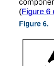
Circuit cards and packaging materials that contain ESD-sensitive components are usually marked with a yellow-and-black warning symbol (Figure 6 on page 2).
Figure 6. ESD Wlarning Symbol
ATTENTION
OBSERVE PRECAUTIONSFOR HANDLING
ELECTROSTATIC SENSITIVE
1
Getting Inside the Computer Protecting Against Damage from Electrostatic Discharge!
CAUTION:
Ensure that your palm is not in contact with the non-component side of the board.
To avoid damaging ESD-sensitive components, follow these rules:
• Handle ESD-sensitive circuit cards only after attaching a wrist strap to the bare wrist. Attach the other end of the wrist strap to a ground that
terminates at the system ground, such as any unpainted metallic chassis surface.
1
Getting Inside the Computer Protecting Against Damage from Electrostatic Discharge1
Getting Inside the Computer Protecting Against Damage from Electrostatic DischargeFigure 8. How to Hold a Large Circuit Card
!
CAUTION:
1
Getting Inside the Computer Protecting Against Damage from Electrostatic Discharge• Keep circuit cards away from plastics and other synthetic materials such as polyester clothing.
• Do not hand circuit cards to another person unless that person is grounded at the same potential level.
• Hold devices such as a hard disk, floppy drive, or streaming tape in the same manner as a large circuit card. The ESD-sensitive area of these components is located on the bottom surface (Figure 9 on page 6).
Figure 9. ESD-Sensitive Area of an Electronic Component
1
Getting Inside the Computer Removing Power from the MAP/100CRemoving Power from the MAP/100C
The MAP/100C can operate with either AC or DC power.
Removing AC Power
The MAP/100C requires a dedicated power line. The power cord connects to the top of the MAP/100C at the point labeled “AC power input receptacle.” Before you begin any work in the MAP/100C you must disconnect the incoming power.
To remove AC power from the MAP/100C, do the following:
1 Shut down the voice system. See “Administer the Voice System,” in “Common System Procedures,” in the Intuity CONVERSANT System Reference, 585-313-205.
2 Shut down the Intuity CONVERSANT system. See “Shut Down the System,” in “Common System Procedures,” in the Intuity CONVERSANT System Reference, 585-313-205.
3 Turn off the monitor’s power switch.
The green or amber lamp on the front bottom of the monitor should be off.
1
Getting Inside the Computer Removing Power from the MAP/100C1
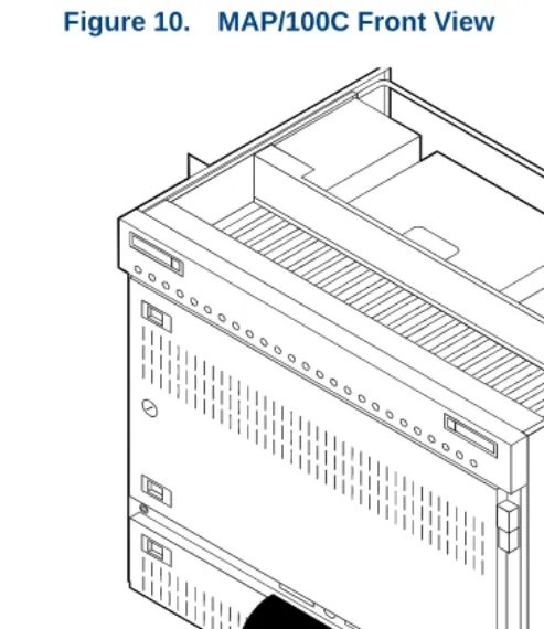
Getting Inside the Computer Removing Power from the MAP/100C5 Turn off the circuit breaker on the back of the MAP/100C (Figure 11 on page 9).
Figure 11. MAP/100C Back View
1
Getting Inside the Computer Removing Power from the MAP/100C7 Observe the correct lock-out/tag-out precautions for isolating power as outlined in the Lucent Technologies lock-out/tag-out procedure.
Removing DC Power
To remove DC power from the MAP/100C, do the following:
1 Shut down the voice system. See “Administer the Voice System,” in “Common System Procedures,” in the Intuity CONVERSANT System Reference, 585-313-205.
2 Shut down the Intuity CONVERSANT system. See “Shut Down the System,” in “Common System Procedures,” in the Intuity CONVERSANT System Reference, 585-313-205.
3 Turn off the monitor’s power switch.
The green or amber lamp on the front bottom of the monitor should be off.
4 Turn off the power switch on the lower front of the MAP/100C (Figure 10 on page 8).
1
Getting Inside the Computer Accessing the Circuit Card CageAccessing the Circuit Card Cage
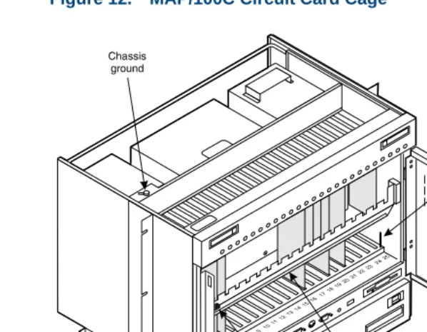
The circuit card cage houses the circuit cards used by the Intuity CONVERSANT system. See Appendix A, System Configuration for the placement of the circuit cards within the circuit card cage.
To access the circuit card cage you must
• Open the front door
• Remove the circuit card retaining bracket
Opening the Front Door
To open the front door, do the following:
1 Loosen the 1/4-turn latch on the MAP/100C front door (Figure 10 on page 8).
2 Disengage the slide latches on the left side of the door
(Figure 10 on page 8) by pushing them toward the center.
1
Getting Inside the Computer Accessing the Circuit Card Cage1
Getting Inside the Computer Accessing the Peripheral BayRemoving the Circuit Card Cage Retaining Bracket
To remove the circuit card cage retaining bracket, do the following:
1 Pull the knurled knob, on the left of the circuit card cage retaining bracket, toward the center of the MAP/100C until it is released from the hole in the chassis.
2 Gently pull on the left side of the circuit card retaining bracket to remove the bracket from the MAP/100C.
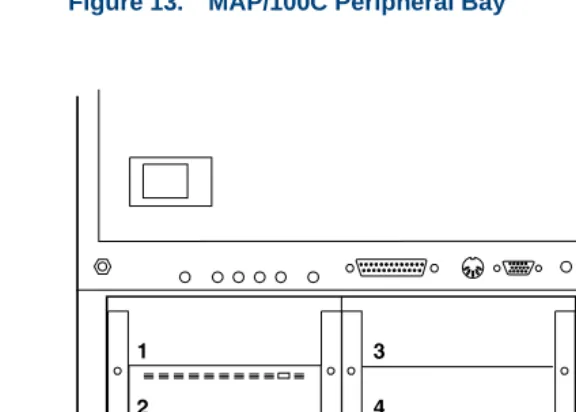
Accessing the Peripheral Bay
The peripheral bay houses the hard disk drives, the floppy disk drive, and the SCSI tape drive. See Appendix A, System Configuration for the placement of these components within the peripheral bay.
The peripheral bay can be accessed from the front or the back.
Accessing the Peripheral Bay from the Front
To access the peripheral bay from the front, do the following:
1 Disengage the slide latches on the left side of the door
1
Getting Inside the Computer Accessing the Peripheral Bay2 Swing the door down as far as possible (Figure 13 on page 14).
1
Getting Inside the Computer Accessing the Peripheral BayAccessing the Peripheral Bay from the Back
To access the peripheral bay from the back, do the following:
1 Release the slide latches on the front of the MAP/100C.
2 Pull the unit forward.
3 Loosen the captive screws on the rear peripheral bay door.
1
Getting Inside the Computer Accessing the Peripheral Bay1
Getting Inside the Computer Restoring Power to the MAP/100CRestoring Power to the MAP/100C
To restore power to the MAP/100C, do the following:
1 Plug the MAP/100C power cord into the designated power outlet.
2 Turn on the circuit breaker on the back of the MAP/100C (Figure 11 on page 9).
3 Turn on the power switch on the lower front of the MAP/100C (Figure 10 on page 8).
4 Turn on the monitor’s power switch.
2
Installing or Replacing Circuit
Cards
Overview
This chapter provides information to ensure that circuit cards are installed correctly and resource options are set correctly on the MAP/100C system. Topics covered include:
• Configuring circuit cards in the MAP/100C
• Types of circuit cards
• General steps for circuit card installation
• Specific procedures for installation of standard and optional MAP/100C circuit cards
2
Installing or Replacing Circuit Cards General ProceduresGeneral Procedures
The general procedures include:
• Removing a Circuit Card on page 19
• Installing a Circuit Card on page 21
Removing a Circuit Card
!
CAUTION:
Observe proper electrostatic discharge precautions when you handle computer components. Wear an antistatic wrist strap that touches your bare skin and connect the strap cable to an earth ground. See the guidelines in
Protecting Against Damage from Electrostatic Discharge on page 2, in
Chapter 1, Getting Inside the Computer .
To remove a circuit card, do the following.
1 Verify that the replacement equipment is on site and appears to be in usable condition, with no obvious shipping damage.
2
Installing or Replacing Circuit Cards General Procedures2 If the system is in service, do the following:
a Stop the voice system. See “Administer the Voice System,” in
“Common System Procedures,” in the Intuity CONVERSANT System Reference, 585-313-205.
b Shut down the voice system. See “Administer the Voice System,” in “Common System Procedures,” in the Intuity CONVERSANT System Reference, 585-313-205.
c Shut down the Intuity CONVERSANT system. See “Shut Down the System,” in “Common System Procedures,” in the Intuity
CONVERSANT System Reference, 585-313-205.
3 Remove power from the MAP/100C. See Removing Power from the
MAP/100C on page 7 in Chapter 1, Getting Inside the Computer .
4 Access the circuit card cage. See Accessing the Circuit Card Cage on
page 11 in Chapter 1, Getting Inside the Computer .
5 Locate the card to be replaced within the card cage. Disconnect any attached cables. Note the connectivity of each cable.
6 If there are ribbon cables attached to other cards which would impede the removal of the card, disconnect them and place them to the side. Note the connectivity of each cable.
2
Installing or Replacing Circuit Cards General Procedures8 Remove the circuit card from the backplane slot by gently pulling at the top corners of the circuit card.
Note: The backplane connector slots are labeled 1 through 25. Make sure to install the replacement card in the same backplane slot.
9 Remove the circuit card from the MAP/100C chassis.
!
CAUTION:
Hold the circuit card carefully by the edges and place it on a grounded mat.
See Protecting Against Damage from Electrostatic Discharge on page 2 in
Chapter 1, Getting Inside the Computer for detailed electrostatic discharge
precautions.
Installing a Circuit Card
!
CAUTION:
Observe proper electrostatic discharge precautions when you handle computer components. Wear an antistatic wrist strap that touches your bare skin and connect the strap cable to an earth ground. See Protecting Against
Damage from Electrostatic Discharge on page 2 in Chapter 1, Getting Inside
the Computer for detailed electrostatic discharge precautions.
To install a circuit card, do the following:
2
Installing or Replacing Circuit Cards General ProceduresNote: Keep the package and all ESD protective wrapping. If you must return a card for repair, re-use of the replacement unit packaging is necessary to meet the manufacturer’s warranty.
2 Verify the circuit card switch and jumper settings. Ensure address switches and jumpers are set to match the old card.
Note: See the specific instructions, listed later in this chapter, for each type of circuit card being installed. Then continue with Step 3.
3 Holding the circuit card by its upper corners, slide the card into the backplane connector slot position from which you removed the damaged card.
4 Apply even pressure to both corners of the circuit card until it is locked into the backplane.
5 Secure the circuit card faceplate into position by replacing the retaining screw.
6 Return all cables on the new card. Make sure these cables are attached to their proper terminations.
7 Return all cables removed from other cards. Make sure these cables are attached to their proper terminations.
2
Installing or Replacing Circuit Cards Settings for Optional Circuit Cards9 Apply power to the unit. See Restoring Power to the MAP/100C on page 17, in Chapter 1, Getting Inside the Computer .
10 Reboot the Intuity CONVERSANT system. See “Reboot the System,” in “Common System Procedures,” in the Intuity CONVERSANT System Reference, 585-313-205.
Settings for Optional Circuit Cards
!
CAUTION:
Observe proper electrostatic discharge precautions when you handle computer components. Wear an antistatic wrist strap that touches your bare skin and connect the strap cable to an earth ground. See Protecting Against
Damage from Electrostatic Discharge on page 2, in Chapter 1, Getting Inside
the Computer for detailed electrostatic discharge precautions.
This section provides the following information on the optional feature circuit cards:
• Switch and jumper settings
2
Installing or Replacing Circuit Cards Settings for Optional Circuit CardsIn general, circuit cards are not preset at the factory. You must set the switches and jumpers (resource options) before you install the cards. When you set the switches according to the instructions in this book, remember that OFF is equivalent to open and ON is equivalent to closed.
Tip/Ring Circuit Cards
The Tip/Ring circuit cards provide the channels which are used by the Intuity CONVERSANT system. The MAP/100C accommodates eleven Tip/Ring circuit cards. The Tip/Ring circuit card can be any of the following types:
• AYC29 (IVP6-IA)
• AYC10 (IVC6)
• AYC30 (NGTR)
The following section covers the resource option settings for each type of T/R card. Many of the figures referenced illustrate settings for more than one type of T/R card.
The six switches on Switch Bank A adjust the termination impedance that each Tip/Ring interface presents to the network. This adjustment is
sometimes necessary to ensure an adequate impedance match between the network and the telephone hybrid on the Tip/Ring card.
2
Installing or Replacing Circuit Cards Settings for Optional Circuit CardsIn general, you should leave all switches on Switch Bank A in the factory default “OPEN” position. If the system shows problems such as not
recognizing touch tones, touch-tone simulation by outgoing speech (speech abruptly stops during playback), or unreliable detection of touch tones during playback (playback does not stop when a touch tone is entered), moving the switch that corresponds to the channel exhibiting the conditions to the “CLOSED” position may solve the problem.
2
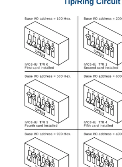
Installing or Replacing Circuit Cards Settings for Optional Circuit CardsFigure 15. Settings for Switches on the IVP6-IA (AYC29) and IVC6 (AYC10) Tip/Ring Circuit Cards T/R-0 through T/R-7
Rocker switches 5 and 6 can be set either open or closed.
Note:
Base I/O address = 100 Hex.
IVC6-IU T/R 0 First card installed
Base I/O address = 200 Hex.
IVC6-IU T/R 1 Second card installed
Base I/O address = 300 Hex.
IVC6-IU T/R 2 Third card installed
Base I/O address = 500 Hex.
IVC6-IU T/R 3 Fourth card installed
Base I/O address = 600 Hex.
IVC6-IU T/R 4 Fifth card installed
Base I/O address = 700 Hex.
Base I/O address = b00 Hex. IVC6-IU T/R 5 Sixth card installed
IVC6-IU T/R 8 Ninth card installed Base I/O address = 900 Hex.
Base I/O address = d00 Hex. IVC6-IU T/R 6 Seventh card installed
IVC6-IU T/R 9
Base I/O address = a00 Hex.
Base I/O address = e00 Hex. IVC6-IU T/R 7 Eighth card installed
2
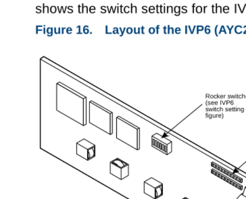
Installing or Replacing Circuit Cards Settings for Optional Circuit CardsIVP6-IA (AYC29) Circuit Card
The IVP6-IA (AYC29) circuit card (Figure 16 on page 27) provides six channels. This circuit card contains switches that you must set before you install the circuit card in the MAP/100C.
Each Tip/Ring card in the system must have a unique address. To set these addresses, the switches must be configured properly. Figure 15 on page 26
shows the switch settings for the IVP6-IA (AYC29) circuit card.
Figure 16. Layout of the IVP6 (AYC29) Tip/Ring Circuit Card
Modular jacks
Audio input
Audio output TDM bus
2
Installing or Replacing Circuit Cards Settings for Optional Circuit CardsIVC6 (AYC10) Circuit Card
The IVC6 (AYC10) circuit card (Figure 17 on page 28) provides six channels. This circuit card contains switches that you must set before you install the circuit card in the MAP/100C.
Figure 17. IVC6 (AYC10) Tip/Ring Circuit Card
8-pin modular jacks
Audio input
Audio output TDM bus
terminator SIPs Rocker
2
Installing or Replacing Circuit Cards Settings for Optional Circuit CardsEach Tip/Ring card in the system must have a unique address. To set these addresses, the switches must be configured properly. Figure 15 on page 26
shows the switch settings for the IVC6 (AYC10) circuit card.
NGTR (AYC30)
Circuit Card The NGTR (AYC30) circuit card (channels. This circuit card contains switches that you must set before you Figure 18 on page 30) provides six
2
Installing or Replacing Circuit Cards Settings for Optional Circuit CardsFigure 18. NGTR (AYC30)
ngtr KLC 070296 I/O address switch
TDM bus B
TDM bus A TDM bus terminator SIPs
8-pin modular jacks
2
Installing or Replacing Circuit Cards Settings for Optional Circuit CardsEach Tip/Ring circuit card in the system must have a unique address. To set these addresses, the switch must be configured properly. Figure 19 on page 31 shows the switch settings for the NGTR (AYC30) circuit card.
2
Installing or Replacing Circuit Cards Settings for Optional Circuit CardsInstalling the Tip/Ring Circuit Card Driver
Note: If the Tip/Ring circuit cards are not recognized when the voice system is started or if other problems are noticed with the Tip/Ring circuit card driver, it may be necessary to remove and reinstall the Tip/Ring circuit card driver.
Occasionally dynamically loadable drivers fail to load into the UnixWare kernel properly.
To install the Tip/Ring circuit card driver, do the following:
1 Stop the voice system. See “Administer the Voice System,” in “Common System Procedures,” in the Intuity CONVERSANT System Reference, 585-313-205.
2 Run the Hardware Resource Allocator to determine the configuration and placement of the Tip/Ring circuit cards to be installed. See Adding
Hardware to an Existing Configuration on page 473 in Appendix A,
System Configuration.
3 If you are not already logged in as root, do so now.
4 Enter pkgadd -d diskette1
The system displays the following message: Insert diskette into Floppy Drive 1. Type [go] when ready,
2
Installing or Replacing Circuit Cards Settings for Optional Circuit Cards5 Insert the diskette labeled “Tip/Ring Board Driver 1 of 1” into the diskette drive.
6 Press E N T E R.
The system displays the following message:
Installation in progress -- do not remove the diskette.
The following packages are available: 1. tipring INTUITY Tip/Ring Board Driver
(i486)
Select package(s) you wish to process (or ‘all’ to process all packages). (default: all) [?,??,q]:
7 Press E N T E R.
The system displays the following message: PROCESSING:
Set: INTUITY Tip/Ring Board Driver (tipring) from <diskette1>
INTUITY Tip/Ring Board Driver (i486)
2
Installing or Replacing Circuit Cards Settings for Optional Circuit CardsThe system displays several status messages and then the following message:
Please enter the IRQ:
8 Enter the IRQ provided by the Hardware Resource Allocator.
The system displays several status messages and then the following message:
Installation of INTUITY Tip/Ring Board Driver (tipring) was successful.
Insert diskette into Floppy Drive 1. Type [go] when ready,
or [q] to quit: (default: go)
9 Enter q
10 Remove the diskette labeled “Tip/Ring Board Driver 1 of 1” from the diskette drive.
E1/T1 Circuit Card
2
Installing or Replacing Circuit Cards Settings for Optional Circuit CardsFigure 20. E1/T1 (AYC21) Circuit Card
TDM bus B (reserved for future use)
TDM bus A Bus B terminating resistors Bus A terminating resistors LED 8-pin modular jack TX connector (signal out) RX connector (signal in) SW1 (device number) SW2 (operating mode) Test port (lab use only)
J8 (shield ground) J7
2
Installing or Replacing Circuit Cards Settings for Optional Circuit CardsJumper Settings Figure 21 on page 36 shows the location and correct setting of the E1/T1 circuit card jumpers.
Figure 21. AYC21 Jumper Settings
Switch Settings There are two sets of switches on the E1/T1 circuit card. Figure 22 on page 37 through Figure 24 on page 38 show the correct switch settings.
68302
J12 (IRQ select) J8
Ground RX outer conductor
Ground TX outer conductor
2
Installing or Replacing Circuit Cards Settings for Optional Circuit Cards2
Installing or Replacing Circuit Cards Settings for Optional Circuit CardsFigure 23. AYC21 Operating Mode Switch Settings for E1 Operation
Figure 24. AYC21 Operating Mode Switch Settings for T1 Operation CEPT/E1
75 ohm, BNC jack
2
Installing or Replacing Circuit Cards Settings for Optional Circuit CardsInstalling the E1/T1 Circuit Card Driver
Note: If the E1/T1 circuit cards are not recognized when the voice system is started or if other problems are noticed with the E1/T1 circuit card driver, it may be necessary to remove and reinstall the E1/T1 circuit card driver.
Occasionally dynamically loadable drivers fail to load into the UnixWare kernel properly.
To install the E1/T1 circuit card driver, do the following:
1 If you are not already logged in as root, do so now.
2 Stop the voice system. See “Administer the Voice System,” in “Common System Procedures,” in the Intuity CONVERSANT System Reference, 585-313-205.
3 Enter pkgadd -d diskette1
The system displays the following message: Insert diskette into Floppy Drive 1. Type [go] when ready,
or [q] to quit: (default: go)
4 Insert the diskette labeled “T1/E1 Board Driver 1 of 3” into the diskette drive.
2
Installing or Replacing Circuit Cards Settings for Optional Circuit CardsThe system displays the following message:
Installation in progress -- do not remove the diskette.
The following packages are available: 1. t1driver INTUITY T1/E1 Board Driver
(i486)
Select package(s) you wish to process (or ‘all’ to process all packages). (default: all) [?,??,q]:
6