TSU 600
&
TSU 600e
User Manual
Part Numbers
1202076L1
1202076L1#DC
Trademarks:
Windows is a registered trademark of Microsoft Corp. T-Watch is a trademark of ADTRAN, Inc.
SLC96 is a registered trademark of AT&T
901 Explorer Boulevard P.O. Box 140000 Huntsville, AL 35814-4000
Phone: (256) 963-8000
© 1998 ADTRAN, Inc. All rights reserved.
YEAR 2000 Compliance
All ADTRAN transmission hardware and software products have been tested and found to be fully compliant with the YEAR 2000 requirements. This is true for all models and revisions regardless of the date of manufacture or delivery.
PROVIDED TO THE CUSTOMER IN THIS MANUAL
1. This equipment complies with Part 68 of the FCC rules. The required label is attached to the bottom of the chassis.
2. An FCC compliant telephone cord and modular plug is provided with this equipment. This equipment is designed to be connected to the telephone network or premises wiring using a compatible modu-lar jack which is Part 68 compliant. See installation instructions for details.
3. If your Product causes harm to the telephone network, the Telephone Company may discontinue your service temporarily. If possible, they will notify you in advance. If advance notice is not practical, you will be notified as soon as possible. You will be advised of your right to file a complaint with the FCC.
4. Your telephone company may make changes in its facilities, equip-ment, operations, or procedures that could affect the proper opera-tion of your equipment. If they do, you will be given advance notice so as to give you an opportunity to maintain uninterrupted service.
5. If you experience trouble with the equipment Product, please contact ADTRAN at (256) 963-8000 for repair/warranty information. The telephone company may ask you to disconnect this equipment from the network until the problem has been corrected, or until you are sure the equipment is not malfunctioning.
6. This unit contains no user serviceable parts.
7. The following information may be required when applying to your local telephone company for leased line facilities.
Service Type REN/SOC FIC USOC
1.544 Mbps -SF 6.0N 04DU9-BN RJ-48C 1.544 Mbps - SF and B8ZS 6.0N 04DU9-DN RJ-48C
INTERFERENCE STATEMENT
This equipment has been tested and found to comply with the limits for a Class A digital device, pursuant to Part 15 of the FCC Rules. These lim-its are designed to provide reasonable protection against harmful inter-ference when the equipment is operated in a commercial environment. This equipment generates, uses, and can radiate radio frequency energy and, if not installed and used in accordance with the instruction manual, may cause harmful interference to radio frequencies. Operation of this equipment in a residential area is likely to cause harmful interference in which case the user will be required to correct the interference at his own expense.
Shielded cables must be used with this unit to ensure compliance with Class A FCC limits.
This digital apparatus does not exceed the Class A limits for radio noise emissions from digital apparatus as set out in the interference-causing equipment standard entitled “Digital Apparatus,” ICES-003 of the De-partment of Communications.
The Industry Canada Certification label identifies certified equipment. This certification means that the equipment meets certain telecommu-nications network protective, operational, and safety requirements. The Department does not guarantee the equipment will operate to the user's satisfaction.
Before installing this equipment, users should ensure that it is permissi-ble to be connected to the facilities of the local telecommunications com-pany. The equipment must also be installed using an acceptable method of connection. In some cases, the company's inside wiring associated with a single line individual service may be extended by means of a cer-tified connector assembly (telephone extension cord). The customer should be aware that compliance with the above conditions may not prevent degradation of service in some situations.
Repairs to certified equipment should be made by an authorized Cana-dian maintenance facility designated by the supplier. Any repairs or al-terations made by the user to this equipment, or equipment
malfunctions, may give the telecommunications company cause to re-quest the user to disconnect the equipment.
Users should ensure for their own protection that the electrical ground connections of the power utility, telephone lines and internal metallic waterpipe system, if present, are connected together. This precaution may be particularly important in rural areas.
Users should not attempt to make such connections themselves, but should con-tact the appropriate electric inspection authority, or an electrician, as appropri-ate.
The Load Number (LN) assigned to each terminal device denotes the percentage of the total load to be connected to a telephone loop which is used by the device, to prevent overloading. The termination on a loop may consist of any combination of devices subject only to the equipment that the total of the LNs of all devices does not exceed 100.
TO DIGITAL SERVICES
• An affidavit is required to be given to the telephone company when-ever digital terminal equipment without encoded analog content and billing protection is used to transmit digital signals containing encod-ed analog content which are intendencod-ed for eventual conversion into voiceband analog signals and transmitted on the network.
• The affidavit shall affirm that either no encoded analog content or billing information is being transmitted or that the output of the de-vice meets Part 68 encoded analog content or billing protection spec-ifications.
• End user/customer will be responsible to file an affidavit with the lo-cal exchange carrier when connecting unprotected CPE to a 1.544 Mbps or subrate digital services.
EQUIPMENT TO 1.544 MBPS AND/OR SUBRATE DIGITAL SERVICES
For the work to be performed in the certified territory of ______________________________(telco name)
State of _________________________________
County of ________________________________
I, ___________________________________ (name),
(business address), ______________________ (telephone number) being duly sworn, state:
I have responsibility for the operation and maintenance of the terminal equipment to be connected to 1.544 Mbps and/or ________ subrate dig-ital services. The terminal equipment to be connected complies with Part 68 of the FCC rules except for the encoded analog content and bill-ing protection specifications. With respect to encoded analog content and billing protection:
( ) I attest that all operations associated with the establishment, main-tenance, and adjustment of the digital CPE with respect to analog con-tent and encoded billing protection information continuously complies with Part 68 of the FCC Rules and Regulations.
( ) The digital CPE does not transmit digital signals containing encoded analog content or billing information which is intended to be decoded within the telecommunications network.
( ) The encoded analog content and billing protection is factory set and is not under the control of the customer.
I attest that the operator(s)/maintainer(s) of the digital CPE responsible for the establishment, maintenance, and adjustment of the encoded an-alog content and billing information has (have) been trained to perform these functions by successfully having completed one of the following (check appropriate blocks):
sentative, using training materials and instructions provided by the manufacturer/grantee of the equipment used to encode analog signals; or
( ) C. An independent training course (e.g., trade school or technical institution) recognized by the manufacturer/grantee of the equipment used to encode analog signals; or
( ) D. In lieu of the preceding training requirements, the operator(s)/ maintainer(s) is (are) under the control of a supervisor trained in accor-dance with _________ (circle one) above.
I agree to provide _________________ (telco's name) with proper docu-mentation to demonstrate compliance with the information as provided in the preceding paragraph, if so requested.
_________________________________Signature
_________________________________Title
_________________________________ Date
Transcribed and sworn to before me
This ________ day of ________, 199___
_________________________________
Notary Public
My commission expires:
IMPORTANT SAFETY INSTRUCTIONS
When using your telephone equipment, please follow these basic safety precautions to reduce the risk of fire, electrical shock, or personal injury:
1 Do not use this product near water, such as near a bath tub, wash bowl, kitchen sink, laundry tub, in a wet basement, or near a swimming pool.
2 Avoid using a telephone (other than a cordless-type) dur-ing an electrical storm. There is a remote risk of shock from lightning.
3 Do not use the telephone to report a gas leak in the vicinity of the leak.
Warranty and Customer Service
ADTRAN will replace or repair this product within five years from the date of shipment if the product does not meet its published specifica-tions or if it fails while in service. For detailed warranty, repair, and re-turn information refer to the ADTRAN Equipment Warranty and Repair and Return Policy Procedure.
Return Material Authorization (RMA) is required prior to returning equipment to ADTRAN.
Table of Contents
Chapter 1 Introduction ... 1-1
TSU 600 Overview ... 1-1 Product Description ... 1-1 Standard Features in the TSU 600... 1-2 TSU Option Modules ... 1-3 Option Module Architecture ... 1-4 TSU 600 Configuration Applications ... 1-5 Router, PBX, Video Conferencing Application... 1-5 Drop and Insert, Voice, and Router Application... 1-6
Chapter 2 Installation ... 2-1
Set User Passcode ... 2-12 Set Unit Identification ... 2-12 Set Control Port ... 2-13 Chain-In (PC) ...2-13 Chain In/Chain Out ...2-13 Normal Power-Up Procedure... 2-14
Chapter 3 Operation ... 3-1
Front Panel ... 3-1 CSU Status LEDs ... 3-2 Module Status LEDs ... 3-3 Operation Keys ... 3-5 General Menu Operation ... 3-5 Selecting and Activating a Menu Item ... 3-6 Editing the Data Field ... 3-7 Display Only Data Fields ... 3-8 Exit Any Menu Field Operation Or Display ... 3-8 Data Port Identification ... 3-9 Front Panel Menu Structure... 3-10 Alternate Methods of Control... 3-11 T-Watch PRO (ADTRAN PC Program) ...3-11 T-Watch PRO/LAN Connection ... 3-11 T-Watch PRO/EIA-232 Connection ... 3-12 SNMP ... 3-12 Terminal Mode Connection ... 3-13 Telnet Connection ... 3-13
Chapter 4 Status Menu ... 4-1
Network Performance Reports (NI PERF RPTS) ... 4-2 Network Interface Errors (NI ERRORS) ... 4-3 Active Alarms ... 4-4 View History ... 4-4 Port Status... 4-5 Remote Port ... 4-5 Clear Port Alarm... 4-5 ENET Status (600e only) ... 4-6 PS Status (600e only) ... 4-6
Chapter 5 Configuration Menu ... 5-1
Internal Timing ... 5-6 Secondary Timing ... 5-7 Normal (CSU) Timing ... 5-8 Unit Menu ... 5-9 Map Exchange (Map Xchng) Menu ... 5-11 MAP In Use: A(B) Menu ... 5-11 DS0 Map A and DS0 Map B Menu ... 5-12 Create Temp Example ... 5-13 Port Configuration (Port Config) ... 5-15
Chapter 6 Utility Menu ... 6-1
Time/Date ... 6-2 Factory Restore ... 6-2 Set Passcode ... 6-2 Enter Passcode from Other Menus ... 6-2 Change/Set a Passcode ... 6-3 Automatic Time-out Feature ... 6-3 No Passcode Desired ... 6-3 Unit ID ... 6-3 Setting the Unit Identification ... 6-4 No Unit ID Desired ... 6-4 Software Revision (Software Rev) ... 6-4 Port Utility... 6-4 ENET Address (600e only)... 6-4 CMD Mode... 6-4
Chapter 7 Test Menu ... 7-1
Network Tests... 7-2 Loopback Tests ... 7-2 Network Interface Loopbacks... 7-3 Local Loopbck... 7-3 Remote Loopbk... 7-4 Test Pattern ... 7-5 QRSS Pattern ... 7-5 Pattern Result... 7-6 Run Self-Test ... 7-7 Board level tests ... 7-7 Unit level tests ... 7-7 Port Tests ... 7-8 Cancel Tests... 7-8
Initializing the Temp Map ... 8-3 Editing the Temp Map ... 8-4 Applying the Temp Map ... 8-4 Reviewing Maps... 8-4 Remote Menu Access ... 8-5 Management Configuration... 8-5 Unit Access Table ... 8-5 Add New Unit ... 8-6 Modify Unit ... 8-6 Delete Unit ... 8-6 Default Unit Passcode ... 8-7 OK ... 8-7 SNMP Read Community... 8-7 SNMP Read/Write Community ... 8-7 SNMP Trap Community ... 8-8 System Name ...8-8 System Contact ... 8-8 System Location ... 8-8 Auto. Fail Traps Sent ... 8-9 Poll Link Status Traps Sent ... 8-9 Ping IP Host ... 8-9 Telnet/Terminal Time-out ...8-9 Telnet/Terminal Password ... 8-9 Exit ... 8-9 Flash Download... 8-9 Quit Session... 8-9
List of Figures
List of Tables
Chapter 1
Introduction
TSU 600 OVERVIEW
This manual covers the use of the following products:
• TSU 600
• TSU 600 with DC power • TSU 600e
• TSU 600e with DC power
Unless otherwise stated, the TSU 600 refers to all four products.
Product Description
The TSU 600 is a T1/FT1 multiplexer with six option slots and embed-ded SNMP management. The TSU 600’s six option slots accept one of many available option modules for voice and data applications. Each module offers up to four ports for a total of 24 possible voice or data ports.
The TSU 600 serves as the link between user data sources such as:
• local area network (LAN) bridges • routers,
• computers, • CAD systems,
• teleconferencing equipment, and • PBXs.
Changes in the configuration do not disrupt data flow in channels that are not being reconfigured. The unique architecture and the availability of option modules provides a path for growth to accommodate future requirements.
The TSU 600 offers a wide variety of network management options. You can manage via SNMP through the 10BaseT (600e only) or chain-in ports. If you are using T-Watch PRO, a Microsoft Windows® program, you can manage the TSU 600 via the same 10BaseT (600e only) or chain-in ports. An enhanced VT-100 termchain-inal chain-interface is also provided.
Standard Features in the TSU 600
The standard features of the TSU 600 are listed below:
• A single T1 interface
• Six slots to house option modules with up to four additional data ports, including voice
• Architecture that allows mix of port types to meet the data interface requirements
• Easy configuration capabilities using simplistic menus displayed in a liquid crystal display (LCD) window operated by a front panel key-pad
• SNMP, Telnet, and T-Watch PRO management via SLIP or 10BaseT (600e only)
• Ability to proxy for “agentless” units • Enhanced terminal mode
• Support for a redundant AC power supply (600e only)
• Two programmable configuration maps that define the bandwidth allocation between data ports
• Data drop and insert, as well as full drop and insert • Flash memory for software updates
• Timing selectable from the network, from the slot 1 data port, inter-nally, or from a secondary interface
• QRSS; 511 test patterns using Nx option
TSU Option Modules
Module Name
Description
DSX1 Short haul T1 interface for operation with a PBX (Terminal Interface).
Full Drop and Insert Permits the dropping of data and insertion of new data into the same DS0 time slot. This module includes a long haul DS1 interface. It can also be used as a second DS1 interface to provide up to 3 MB aggregate throughput.
Nx56/64 Serial Interface Provides a V.35 serial interface in either sin-gle or dual versions.
NxIQ Frame-relay aware device that provides
detailed information regarding the health and performance of the frame relay circuit.
Voice Interface 2/4 channel FXS/FX0/E&M.
OCU DP Interfaces to DDS or 4-wire Switched-56.
DSU DP Provides two sync or async ports (232 or V.35).
Dial Backup Allows for backup of data upon network T1 failure.
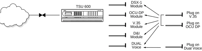
Option Module Architecture
The TSU 600 features a unique architecture that allows the addition of six option modules and plug-on boards, providing an opportunity for growth to accommodate many applications. See Figure 1-1. This unique approach allows you to mix interface types to meet any application.
Figure 1-1. TSU 600 Option Modules
TSU 600
DSX-1 Module
Plug on V.35
Plug on OCU DP
Plug on Dual Voice OCU-DP
Module
V.35 Module
D&I Module
TSU 600 CONFIGURATION APPLICATIONS
The following examples illustrate possible configurations of TSU 600 applications.
Router, PBX, Video Conferencing Application
In this application, an Nx54/64 module provides a V.35 interface to a router. The PBX is interfaced to the TSU 600 with the DSX-1 module. An OCU DP module and OCU DP plug-on board provide two switched 56 circuits for video conferencing. The SLIP port or 10BaseT port (600e only) allows SNMP network management over the LAN. See Figure 1-2.
Figure 1-2. Router, PBX, Video Conferencing Application Set Up
TSU 600 PBX
VIDEO CONFERENCING
ROUTER
SNMP NETWORK MANAGEMENT WORKSTATION
Drop and Insert, Voice, and Router Application
The TSU 600 provides a router interface with an Nx56/64 module. A drop and insert module provides a second T1 interface to a remote TSU. T-WATCH PRO (which runs on a PC) easily manages the network. FXO modules are used to provide PBX extensions to remote sites. See Figure
1-3.
Figure 1-3. Drop and Insert, Voice, and Router Application
Set Up
ROUTER
ROUTER
0
T-WATCH
OK TEST ALARMOK TEST ALARMOK TEST ERROR ALARM DSU MODULE CSU
Chapter 2
Installation
UNPACK, INSPECT, POWER UP
Receipt Inspection
Carefully inspect the TSU 600 for shipping damages. If you suspect damage, file a claim immediately with the carrier and then contact ADT-RAN Customer Service (see the inside last page of this manual). If pos-sible, keep the original shipping container for use in shipping the TSU 600 back for repair or for verification of damage during shipment.
ADTRAN Shipments Include
• The TSU 600
• A line interface cable: an 8-position modular to 8-position modular (15 ft.)
• A DB-25 to modular adapter
• An 8-position, 6-foot modular cable for the Chain-In port connection
• The User Manual • Rackmount Brackets • Rackmount Data Sheet
Customer Provides
• Cables for any expansion modules to be used with the TSU 600 • 10BaseT cable for connection to a LAN or router (if you plan to use
Power Connection
The AC- powered TSU 600 is equipped with a captive, 8-foot power cord, terminated by a 3-prong plug which connects to a grounded pow-er receptacle.
Power to the TSU 600 must be from a grounded 90-120 VAC, 50/ 60Hz source.
DC Powered Units
The DC-powered TSU 600 (1202076L1#DC or 1202076L2#DC) is equipped with a terminal strip on the rear of the unit. The power source should be connected to the terminal strip according to the polarity mark-ings on the unit.
Example:
A -48V source would be connected with the -48V return attached to the (+) terminal and the -48VDC attached to the (-) terminal. Power must be from a DC source in the range of 21 to 26 VDC or in the range of 40 to 56VDC.
The protective cover should be reinstalled over the terminal strip once the power source is connected.
The DC-powered TSU 600 is to be installed only in restricted areas (ded-icated equipment rooms, equipment closets, etc.) in accordance with Ar-ticles 110-16 and 110-18 of the National Electric Code, ANSI/NFPA 70.
Backup Power Supply (600e only)
Installing and Replacing the Power Supply
The following steps show how to install a new supply or replace a failed supply.
Power does not have to be turned off on a working supply to add a new supply or replace a failed one.
Step
Action
1
One Power SupplyIf only one supply is installed in the chassis, remove the blank panel covering the unused power supply slot.
Two Power Supplies
If two power supplies are installed, the failed supply can be identified by the alarm on the front panel LCD. The alarm message will identify a failure on Power Supply A or Power Supply B. The option slot legend on the rear panel shows the location of each power supply. Turn the power switch to Off on the failed supply and unplug the power cord from the power source.
2
Remove the two screws that secure the power supply mod-ule to the TSU 600e chassis and remove the failed power sup-ply module.3
Remove the new power supply from the shipping con-tainer. Make sure the power switch is in theOff position.4
Plug the new supply into the open power supply slot andinstall the two screws on the power supply module
5
Plug the new power supply cord into a grounded 115 VAC, 50/60 Hz power receptable.GROUNDING INSTRUCTIONS
The grounding instruction information is from the Underwriters'
Labo-ratory UL 1950, 3rd Edition.
An equipment grounding conductor that is not smaller in size than the ungrounded branch-circuit supply conductors is to be installed as part of the circuit that supplies the product or system.
• Bare, covered, or insulated grounding conductors are acceptable. • Individually covered or insulated equipment grounding conductors
shall have a continuous outer finish that is either green, or green with one or more yellow stripes.
• The equipment grounding conductor is to be connected to ground at the service equipment.
• The attachment-plug receptacles in the vicinity of the product or sys-tem are all to be of a grounding type.
• The equipment grounding conductors serving these receptacles are to be connected to earth ground at the service equipment.
• A supplementary equipment grounding conductor shall be installed between the product or system and ground that is in addition to the equipment grounding conductor in the power-supply cord.
• The supplementary equipment grounding conductor shall not be smaller in size than the ungrounded branch-circuit supply conduc-tors.
• The supplementary equipment grounding conductor shall be con-nected to the product at the terminal provided, and shall be connect-ed to ground in a manner that will retain the ground connection when the product is unplugged from the receptacle.
• The connection to ground of the supplementary equipment ground-ing conductor shall be in compliance with the rules for terminatground-ing bonding jumpers at Part K or Article 250 of the National Electrical Code, ANSI/NFPA 70.
• Termination of the supplementary equipment grounding conductor is permitted to be made to building steel, to a metal electrical raceway system, or to any grounded item that is permanently and reliably connected to the electrical service equipment ground.
• The supplemental grounding conductor shall be connected to the equipment using a number 8 ring terminal.
• The terminal should be fastened to the grounding lug provided on the rear panel of the equipment.
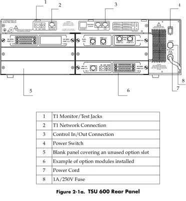
IDENTIFICATION OF REAR PANEL LAYOUT
Figures 2-1a, Figure 2-1b, Figure 2-1c, and Figure 2-1d show the config-uration for the rear panels of the TSU 600, TSU 600 with DC Power, TSU 600e, and TSU 600e with DC power.
Figure 2-1a. TSU 600 Rear Panel
1 T1 Monitor/Test Jacks
2 T1 Network Connection
3 Control In/Out Connection
4 Power Switch
5 Blank panel covering an unused option slot
6 Example of option modules installed
7 Power Cord
8 1A/250V Fuse
PORT X.3 PORT X.3 PORT X.4 DUAL
FXS
DUAL FXS PORT X.1 PORT X.2
NX 56/64 PORT X.2 V.35 SEC. NI PORT X.1 DS-1
IN OUT MON NX 56/64 PORT X.2 V.35 NX 56/64 PORT X.1 V.35 CAUTION-RISK OF ELECTRIC SHOCK
SUPPLEMENTAL EARTH GROUND MUST BE CONNECTED PRIOR TO CONNECTION OF TELECOMMUNICATION WIRING. MODULE 1 MODULE 2 MODULE 3 MODULE 4 MODULE 5 MODULE 6 P W R A P W R B CONTROL /CHAIN IN OUT 10 BASE T
IN OUT MON NETWORK
SEE MANUAL BEFORE REMOVING POWER SUPPLY CAUTION:
MAINTENANCE TO BE PERFORMED BY TRAINED SERVICE PERSONEL ONLY
ALL EMPTY SLOTS MUST BE COVERED WITH BLANK PANELS
(600e ONLY)
O I
1A/250V
CAUTION: FOR CONTINUED PROTECTION AGAINST RISK OF FIRE, REPLACE ONLY WITH SAME TYPE AND RATING
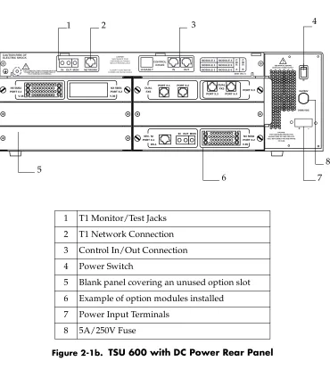
Figure 2-1b. TSU 600 with DC Power Rear Panel
1 T1 Monitor/Test Jacks
2 T1 Network Connection
3 Control In/Out Connection
4 Power Switch
5 Blank panel covering an unused option slot
6 Example of option modules installed
7 Power Input Terminals
8 5A/250V Fuse
PORT X.3 PORT X.3 PORT X.4 DUAL
FXS
DUAL FXS PORT X.1 PORT X.2
NX 56/64 PORT X.2 V.35 SEC. NI PORT X.1 DS-1
IN OUT MON NX 56/64 PORT X.2 V.35 NX 56/64 PORT X.1 V.35 CAUTION-RISK OF ELECTRIC SHOCK
SUPPLEMENTAL EARTH GROUND MUST BE CONNECTED PRIOR TO CONNECTION OF TELECOMMUNICATION WIRING. MODULE 1 MODULE 2 MODULE 3 MODULE 4 MODULE 5 MODULE 6 P W R A P W R B CONTROL /CHAIN IN OUT 10 BASE T
INOUT MON NETWORK
SEE MANUAL BEFORE REMOVING POWER SUPPLY CAUTION:
MAINTENANCE TO BE PERFORMED BY TRAINED SERVICE PERSONEL ONLY
ALL EMPTY SLOTS MUST BE COVERED WITH BLANK PANELS
(600e ONLY)
O I
5A/250V
CAUTION: FOR CONTINUED PROTECTION AGAINST RISK OF FIRE, REPLACE ONLY WITH SAME TYPE AND RATING
OF FUSE.
24/48 VDC
+
-2 3 4
5
6 7
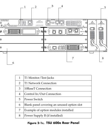
Figure 2-1c. TSU 600e Rear Panel
1 T1 Monitor/Test Jacks
2 T1 Network Connection
3 10BaseT Connection
4 Control In/Out Connection
5 Power Switch
6 Blank panel covering an unused option slot
7 Example of option modules installed
8 Power Supply B (if installed)
PORT X.3 PORT X.3 PORT X.4 DUAL
FXS
DUAL FXS PORT X.1 PORT X.2
NX 56/64 PORT X.2 V.35 SEC. NI PORT X.1 DS-1
IN OUT MON NX 56/64 PORT X.2 V.35 NX 56/64 PORT X.1 V.35 CAUTION-RISK OF ELECTRIC SHOCK
SUPPLEMENTAL EARTH GROUND MUST BE CONNECTED PRIOR TO CONNECTION OF TELECOMMUNICATION WIRING. MODULE 1 MODULE 2 MODULE 3 MODULE 4 MODULE 5 MODULE 6 P W R A P W R B CONTROL /CHAIN IN OUT 10 BASE T
INOUT MON NETWORK
90-120 VAC 50/60 HZ. .7A MAX 90-120 VAC 50/60 HZ. .7A MAX
SEE MANUAL BEFORE REMOVING POWER SUPPLY SEE MANUAL BEFORE REMOVING POWER SUPPLY CAUTION:
MAINTENANCE TO BE PERFORMED BY TRAINED SERVICE PERSONEL ONLY
ALL EMPTY SLOTS MUST BE COVERED WITH BLANK PANELS
(600e ONLY)
O I O I
1 2 3 4 5
6
Figure 2-1d. TSU 600e with DC Power Rear Panel
1 T1 Monitor/Test Jacks
2 T1 Network Connection
3 10BaseT Connection
4 Control In/Out Connection
5 Power Switch
6 5A/250V Fuse
7 Blank panel covering an unused option slot
8 Example of option modules installed
9 Power Input Terminals
PORT X.3 PORT X.3 PORT X.4 DUAL
FXS
DUAL FXS PORT X.1 PORT X.2
NX 56/64 PORT X.2 V.35 SEC. NI PORT X.1 DS-1
IN OUT MON NX 56/64 PORT X.2 V.35 NX 56/64 PORT X.1 V.35 CAUTION-RISK OF ELECTRIC SHOCK
SUPPLEMENTAL EARTH GROUND MUST BE CONNECTED PRIOR TO CONNECTION OF TELECOMMUNICATION WIRING. MODULE 1 MODULE 2 MODULE 3 MODULE 4 MODULE 5 MODULE 6 P W R A P W R B CONTROL /CHAIN IN OUT 10 BASE T
INOUT MON NETWORK
SEE MANUAL BEFORE REMOVING POWER SUPPLY CAUTION:
MAINTENANCE TO BE PERFORMED BY TRAINED SERVICE PERSONEL ONLY
ALL EMPTY SLOTS MUST BE COVERED WITH BLANK PANELS
(600e ONLY)
O I
5A/250V
CAUTION: FOR CONTINUED PROTECTION AGAINST RISK OF FIRE, REPLACE ONLY WITH SAME TYPE AND RATING
OF FUSE.
24/48 HZ.
+
-1 2 3 5
7 8
9
TSU 600 Interfaces
The TSU 600 is equipped with six option slots, management interfaces, and a T1 interface, in the rear panel. See Figure 2-2.
Figure 2-2. TSU 600 Interfaces
Network Interface
The network interface (NI) port provides the connection to the T1. This port complies with the applicable ANSI and AT&T standards. For more information, see Wiring on page B-1.
Network Test Interface
The
IN
andOUT
test jacks
for the network interface provide intrusive test capability for the incoming T1. By connecting to these jacks with test equipment, the T1 connection will be broken, and the test equipment will terminate the incoming T1. TheMON test jack
provides a bridged access jack for non-intrusive monitoring of the incoming T1. When con-nected to this jack, the test equipment should be configured for a bridged termination.Control Port Input
The control port input provides an EIA-232 input from a PC or a modem for control of the TSU 600. You can also use it as a chain input from an-other TSU 600 or TSU 100. For more information, see Wiring on page C-1.
Chain Port Output
TSU 600
PC or Modem
Network
Control Input
Chain Output
TSU 600
Chain Input
Chain Output
NI
Option 10BaseT
NI
10BaseT Interface (600e only)
The 10BaseT interface provides the LAN interface for managing the TSU 600e with SNMP or T-watch PRO. For more information, see Wiring on page C-1.
Option Slot Arrangement
As viewed from the rear of the TSU 600, the slots are numbered as shown in Figure 2-3. All slots are functionally identical except slots one, two, and six. These slots offer additional functions.
Figure 2-3. TSU 600 Slot Designation (Rear View)
Slot 1 Slot 1 is used as the source of DTE timing when the DTE timing mode is selected or as the source of UBR1TE timing when the UBR1TE timing mode is selected. If DTE timing is desired, the DTE interface port sourcing the timing must be connected to Slot 1. This slot will accept all other interface types except Secondary Network interface option modules, includ-ing DSX-1 (PBX), the Full Drop and Insert (D&I) net-work interface, or the multiport Dial Backup (DBU).
Slot 2 Slot 2 is used for the multiport Dial Backup module if it is installed. This slot accepts all other interface types except Secondary Network interface option modules, including DSX-1 (PBX) and the Full Drop and Insert (D&I) network interface.
SLOT 1
DTE TIMING
SLOT 2
SLOT 3
SLOT 4
SLOT 5
SLOT 6
SECONDARY INTERFACE DSX-1; FULL D&I DIAL BACKUP
You can use NxDBU modules in any slot.
Power-up Testing
When shipped from the factory, the TSU 600 is set to factory default con-ditions. At the first application of power, the unit automatically exe-cutes a memory self-test. A full self-test can be run from the front panel, and a passcode and unit ID may be set using the UTIL menu.
Self-Test
Upon a power-up, the LCD displays
Memory Test Now Testing
and the Test LEDs are illuminated.Slots 3-5 Slots 3-5 will accept any interface type except second-ary interface, the interface for DTE timing, or the mul-tiport DBU. If other interfaces have any restriction on their location, this will be specified in the individual option card manual (provided with the option cards).
Slot 6 Slot 6 services any option module type including sec-ondary network interface ports (DSX-1 (PBX) and Full D&I), but not the DTE timing source. If a secondary network interface port is to be used, it must be installed in slot 6.
When . . .
Then . . .
the self-test is complete with no failures detected
the
OK LED
lights up and the LCD momentarily displaysAll Tests
Passed
.The full self-test procedure (invoked from the front panel or T-Watch PRO) consists of the following tests:
Board level tests
Each of the TSU 600 boards contains an on-board processor which exe-cutes a series of tests checking the circuitry on the board.
• RAM and EPROM tests • Verify on-board circuitry
Unit level tests
• Front panel LED verification • Board-to-board interface test
A test pattern is sent from the controller through a loopback on all other boards and checked on the controller. This verifies the data path, clocks, and control signals for the entire chassis.
Initialization
Set User Passcode
The TSU 600 is designed to operate with or without the use of a pass-code. The default condition is without a passpass-code.
If the unit is to be remotely accessed using T-Watch PRO, you must enter a passcode. When managing a number of units, the passcode can be the same for all the units.
The passcode should be a number easily remembered. Once entered, the passcode is required to access any operation other than viewing. See
Set Passcode on page 6-2.
Set Unit Identification
Set Control Port
The TSU 600 can be configured from the control port when T-Watch PRO, SNMP, or the terminal interface is being used.
If the control port is to be used, the control port baud rate must also be selected.
Chain-In (PC)
The unit can be controlled from an external PC connected directly or via modem to the Chain-In port. When using Chain-In, the selection of the Control Port baud rate from 9600 (factory default), 1200, 2400, or 4800, 19200, or 38400 must be made using the Unit Configuration menu. Un-less locked out externally, the front panel can also control the unit.
Chain In/Chain Out
TSU 600 units and other TSUs can be linked together to form a chain.
Figure 2-4 provides an example of a chain-in arrangement with a PC or
a modem. The first TSU 600 in the chain receives controlling input from the PC or modem.
Figure 2-4. Example of Chain In
Subsequent TSUs in the chain are in a position to intake information from another TSU. This in-taking of information from another TSU in the chain is identified as Chain-In. The baud rate for the chained units must match that of the first unit.
Unless locked out externally, the front panel can also control the unit.
TSU 600 PC or Modem
Control Input
Chain Out
TSU 600/ TSU 100/TSU Chain
In
Chain Out
TSU 600/ TSU 100/TSU Chain
In
The Passcode, the Unit ID, and the Control Port settings are stored in a nonvolatile memory. This ensures that they are operable for subsequent power-up sequences.
Normal Power-Up Procedure
After the unit has been put into operation with the initial power-up and initialization, subsequent power-up procedure includes only the Power-Up Self-Test followed by the request for a passcode (password) if this option was selected during initialization.
Chapter 3
Operation
FRONT PANEL
The TSU 600 front panel both monitors operation and controls the con-figuration of the unit. The TSU 600 front panel is shown in Figure 3-1 on page 3-4. Descriptions of each part of the front panel follow.
Name
Description
LCD Window Displays menu items and messages in two lines by 16 characters. It also displays alarm and status information.
Enter Selects active menu items. To select a menu item, press the number of the item. The menu item flashes, indicating it is activated. Press Enter to select the menu item.
Up and down arrows
Up and down arrows are used to scroll through and activate the submenu items available in the current menu. When the submenu items are scrolled, the flashing cursor indicates the active parameters.
Cancel Pressing the Cancel key stops the current activity and returns the display to the previous menu. Repeat until the desired menu level is reached. When a submenu item is displayed, press Cancel to exit the current display and return to the previ-ous menu.
CSU Status LEDs
The CSU status LEDs display the operational condition of the network interface located on the controller board in the unit.
Shift To enter special function keys, press and release
Shift before pressing the key representing the desired character. See Operation Keys on page 3-5 for a description of the function keys.
To activate a special function key rather than a number, press Shift and then the key. If you press the key without using Shift, the numbered item becomes active instead of the special function key.
Name
Description
OK (green) Indicates the operation is in the normal mode and no errors have been detected.
Test (yellow) Indicates that the network interfaces are operating in a test mode. This includes a self-test or a test loopback. When lighted, this LED also indicates that normal data flow is not occurring on the network interface.
Error (red) Indicates an error such as a BPV, OOF, or CRC.
Alarm (red) Indicates an alarm condition has been detected. When the alarm condition is no longer valid, the OK LED activates (turns on).
To view an alarm condition, select the
active alarm menu
item
or selectAlarm
by pressing Shift 8.If the alarm conditions have been corrected, the alarm which caused the activation of the Alarm LED can be viewed under the
Unit History
menu.Module Status LEDs
The module status LEDs display the operational condition of ports in-stalled in the option slots.
Name
Description
OK (green) Indicates the operation is in the normal mode and no errors have been detected.
Test (yellow) Indicates that one of the interfaces is operat-ing in a test mode. This includes a self-test or a test loopback. When lighted, this LED also indicates that normal data flow is not occur-ring in at least one of the module ports.
Alarm (red) Indicates an alarm condition has been detected. When the alarm condition is no longer valid, the
OK LED
activates (turns on).To view an alarm condition, select the active alarm menu item or select
Alarm
by pressingshift 8. If the alarm conditions have been cor-rected, the alarm which caused the activation of the
Alarm LED
can be viewed under theUnit History
menu.System (green) Indicates the status of the power supplies.
If the LED is illuminated green, all installed power supplies are functioning properly.
If the LED is illuminated red, one or both power supplies are not functioning normally.
.
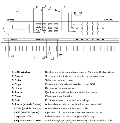
Figure 3-1. TSU 600 Front Panel Layout
1. LCD Window Displays menu items and messages in 2 lines by 16 characters.
2. Cancel Stops current activity and returns to the previous menu.
3. Enter Selects active menu item
4. Copy Copies last data entered into the current DS0.
5. Home Returns to the main menu.
6. Alarm Quick access to the active alarm display menus.
7. Clear Clears data/results fields
8. Shift Provides access to special function keys
9. Alarm (Module Status) Active when an alarm condition has been detected.
10. Test (Module Status) Active when the module is in test mode.
11. OK (Module Status) Operation is in normal mode with no detected errors.
12. System LED Indicates status of power supplies (600e only)
13. Up and Down Arrows Scroll through and activate the submenu items available in the
current menu. The flashing cursor indicates the active parame-ter.
14. OK (CSU Status) Operation is in normal mode with no detected errors.
15. Test (CSU Status) Active when the network interface is in test mode.
16. Error (CSU Status) Indicates errors such as BPV, OOF, and CRC.
17. Alarm (CSU Status) Active when an alarm condition has been detected on the
net-work interface.
TSU 600
1 2 3
COPY * HOME 0 SHIFT # 7 ALARM 8 CLEAR OK ALARM TEST 9
4 5 6
ENTER
CANCEL
1
SYSTEM CSU OK TEST ERROR ALARM 2 3 4 5 6
1 2 3
4 5 6
7 8
9 10 11
12
13 14 15
Operation Keys
General Menu Operation
The TSU 600 uses a multilevel menu structure containing both menu items and data fields. All menu operations and data are displayed in the LCD window. The menu items are numbered and can be viewed by scrolling with the up and down arrows.
Name
Description
Copy Used in the DS0 mapping menu operations to copy the last data entered into the current DS0. This key operates without pressing the Shift key.
Home Returns home to the
Main Menu
from any menu location.Alarm Used as quick access to the active alarm display menus. This can be activated while any other menu item is in use. When the
Alarm Menu
is exited, the unit returns to the location of the same menu that was active when Alarm was selected.Clear Used in various menus to clear data/result fields.
Name
Description
Data Field You can edit menu items followed by a colon (:)
Display Only Field
You cannot edit menu fields followed by an equal symbol (=). This symbol identifies a field used for value display only
Arrows Menus that display small up or down arrows in the lower right corner indicate there are more menu items than are visible on a two-line LCD. Access the additional items with the up or
Selecting and Activating a Menu Item
The front panel menu tree is shown below.
Figure 3-2. Example of Basic Front Panel Menu Travel
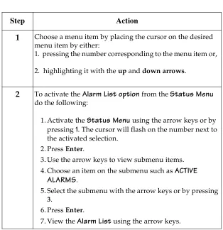
Step
Action
1
Choose a menu item by placing the cursor on the desired menu item by either:1. pressing the number corresponding to the menu item or,
2. highlighting it with the up and down arrows.
2
To activate theAlarm List option
from theStatus Menu
do the following:
1. Activate the
Status Menu
using the arrow keys or by pressing1
. The cursor will flash on the number next to the activated selection.2. Press Enter.
3. Use the arrow keys to view submenu items. 4. Choose an item on the submenu such as
ACTIVE
ALARMS
.5. Select the submenu with the arrow keys or by pressing
3.
6. Press Enter.
7. View the
Alarm List
using the arrow keys.1) NI PERF RPTS 2) NI ERRORS
3) ACTIVE ALARMS (ALARM LIST) 4)VIEW HISTORY END OF LIST 1)STATUS 5) PORT STATUS
Editing the Data Field
Use the following steps to edit data fields preceded by a colon (:).
Step
Action
Result
1
Position the cursor on the submenu item number and press Enter.The cursor moves to the data field (to the right of the submenu item name).
2
Using the arrows, scroll to scan the available value settings.The value settings display one-at-a-time in the data field position.
3
When the desired value is displayed, press Enter to set that value.When the value is set, the cursor moves back to the submenu item position, indicating the operation is complete.
4
Select another submenu field or press Cancel to return to the submenu.Pressing Cancel before pressing
Display Only Data Fields
Data fields preceded by an equal (=) symbol cannot be edited. See Figure
3-3 and the instructions listed below.
Figure 3-3. Display and Data Fields
Exit Any Menu Field Operation Or Display
Press Cancel as many times as required to return to the desired menu level or press Home to return to the main menu.
Step
Action
1 Press Enter to move the cursor to the data field.
2 Use arrows to select
AUTO
and press Enter.• The unit automatically sets the
Line Build Out
. • The display field shows the value actually set. • The equal symbol after LBO in the second linein-dicates the information that follows is displayed data and cannot be edited.
Data Field
Data Port Identification
When configuring the unit, menu selections will include options from data port submenus. Selecting of data ports is necessary because the TSU 600 uses a Slot-Port method to identify which data port the menu item is referencing. If a module containing a
PBX DSX-1 option card
with an
Nx56/64 plug-on interface
is installed in option slot 6, it would be designated as:DSX-1 Passthru=6.1
Where slot=6 and port =1.
The DSX-1 is located in option slot 6 and is the first port in that slot.
Nx56/64=6.2
Where slot=6 and port=2.
The Nx is located in Slot 6 and is the second port in that slot.
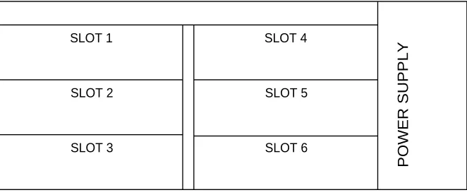
Viewed from the rear of the TSU 600, the module slots are arranged as shown in Figure 3-4.
Figure 3-4. Module Slots, TSU 600
SLOT 4
SLOT 5
SLOT 6 SLOT 1
SLOT 2
SLOT 3
Front Panel Menu Structure
The TSU 600 uses a multilevel menu structure containing both menu items and data fields. All menu operations and data display in the LCD window.
The opening menu is the access point to all other operations. Each
Main
Menu
item has several functions and submenus to identify and access specific parameters.The front panel LCD of the
Main Menu
contains the following options:Option
Description
Status Displays all relevant information for the network and DTE interfaces. For detailed information on status options, see Chapter 4, Status Menu.
Config
(Configuration)
Displays and sets the TSU 600 operational config-uration, including all network interface parame-ters, the allocation of the DS0s, and the port parameters.
For detailed information on configuration options, see Chapter 5, Configuration Menu.
Util (Utilities) Displays and sets system parameters. For detailed information on utility options, see Chapter 6,
Util-ity Menu.
Test The Test menu initiates different types of unit tests and displays test results in the LCD window. For detailed information on test options, see Chapter 7,
Alternate Methods of Control
T-Watch PRO (ADTRAN PC Program)
T-Watch PRO is the ADTRAN PC control program. It provides complete control over the configuration of the TSU 600 using a graphical interface and displays the same status and performance data as the front panel LCD. This data is displayed in the form of tables and graphs.
The T-Watch PRO program has the following capabilities:
• Interfaces with a modem which permits dialing into a remote TSU 600 location to configure the unit or read the status or performance of the unit.
• Receives traps from any TSU product.
• Records and creates display performance data over a 30 day period. • Accesses units via the local area network.
T-Watch PRO/LAN Connection
To set up the TSU 600 to work with T-Watch PRO over the LAN, follow these steps:
Step
Action
1
Set theUnit ID
using the Front Panel.See Unit ID on page 6-3 for more information.
2
SetControl Port
to SLIP or Normal for 10BaseT (600e only) using the Front Panel.3
Configure theIP address default gateway
, and sub-net mask using the Front Panel.The default gateway and subnet masks are not used for SLIP mode.
T-Watch PRO/EIA-232 Connection
To set up the TSU 600 to work with T-Watch PRO over a direct EIA-232 connection, the following steps are required:
SNMP
The ADTRAN TSU 600 supports the Simple Network Management Pro-tocol (SNMP) through the chain-in (SLIP) interface or 10BaseT interface (600e only). See Appendix B, Understanding SNMP for detailed informa-tion.
To use SNMP with the TSU 600, do the following:
Step
Action
1
Set theUnit ID
and thePasscode
using the Front Panel.See Unit ID on page 6-3 and Change/Set a Passcode on page
6-3 for more details.
2
Set theControl Port rate
to the same setting as the PC Com port.3
Connect thePC Com port
to theChain-In port
on the TSU 600 using the DB25 to modular adapter and 6-foot modular cable.4
Follow the installation instructions for T-Watch PRO to start the program and connect to the unit.Step
Action
1
Set Control Port toSLIP
for Chain-In Port orNormal
for 10BaseT (600e only).2
Set the IP address, default gateway, and subnet mask through the front panel.The default gateway and subnet mask are not used in SLIP mode.
3
Load the appropriate MIB browser into the Network Management Station (available on the ADTRAN webpage atTerminal Mode Connection
The TSU 600 provides the front panel menus to a VT-100 type terminal. This mode can be used to configure and monitor the unit. Initiate this mode by typing <ctrl> PTT on the terminal once it is connected to the Chain-In port. For detailed information on this method of control, see
Telnet Terminal Menus on page 8-1.
Telnet Connection
You can connect to the TSU 600 via telnet. Before attempting to connect via telnet, first define the IP address, the default gateway, and subnet mask using the front panel.
The dafault gateway and subnet mask are not used in SLIP mode.
When you begin the Telnet session, you will be prompted for a word. The default password is ADTRAN. You can change this pass-word using the Management submenu. See Default Unit Passcode on page 8-7, for details. The telnet session will time-out after a predefined value that is also set in the Management Menu.
Chapter 4
Status Menu
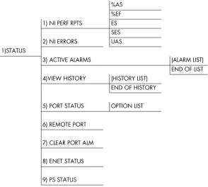
The Status menu branch allows you to view the status of the TSU 600 op-eration. See Figure 4-1.
Figure 4-1. Complete Status Menu
%AS %EF 1) NI PERF RPTS ES
SES 2) NI ERRORS UAS 1)STATUS
3) ACTIVE ALARMS (ALARM LIST) END OF LIST 4)VIEW HISTORY (HISTORY LIST)
END OF HISTORY
5) PORT STATUS OPTION LIST
6) REMOTE PORT
7) CLEAR PORT ALM
8) ENET STATUS
Menu flow is normally depicted from left to right. Arrows on the lower right of the screen indicate the direction of scrolling to use to view addi-tional menu items. At every level of the menu, pressing Cancel returns the system to the previous menu level. Press Cancel repeatedly to return the system to the main menu.
Network Performance Reports (NI PERF RPTS)
The Network Interface Performance Reports display the user copy of the performance data. See Figure 4-2. The TSU 600 maintains this perfor-mance data on the network in compliance with ANSI T1.403 and AT&T document TR54016. The data displayed is data accumulated over the last 15 minutes and over the last 24 hours.
Use the scroll keys to access the complete display of the following report fields:
Figure 4-2. Network Interface Performance Report
%AS % of available seconds
%EF % of error free seconds
ES Number of errored seconds (1 or more errors/second
SES Number of severely errored seconds (more than 320 errors/second)
UAS Number of unavailable seconds (10 or more consecutive seconds)
15 Minutes
24 Hours
If insufficient time has passed to collect data, NA displays. Continue with standard operating procedures to exit the display.
When this menu is active, performance data can be cleared by pressing
Clear (Shift 9) on the keypad. Only the user copy of the performance data is cleared.
Since only the user’s copy of performance data is cleared by the TSU 600, the data displayed here might be different from the data sent to the net-work as PRM data.
Network Interface Errors (NI ERRORS)
The NI Errors submenu displays the types of errors the Network Intface (NI) detects. A blinking CSU error LED indicates that network er-rors are detected.
The asterisk (*) above an item indicates the type of errors detected. The error types are as follows:
CRC CRC-6 bit errors based on the FDL. This is valid only in ESF mode.
BPV Bipolar violations.
XS0 Excess zeros.
Active Alarms
This menu item displays a list of current alarms reported by either the base controller or any of the ports. If no alarms are current, the menu item displays
End of List
. See Figure 4-3.This display includes two lines of text. The top line is the alarm source. The bottom line is the alarm message. A list of alarm messages is found in Appendix C, System Messages, on page C-1.
In addition to normal menu operation, you can also access this menu item with the Alarm function (Shift 8) on the keypad. If one or more of the
Alarm LEDs
are illuminated, an alarm is present. Press Cancel to re-turn to the previous menu item.Figure 4-3. Display of Alarm Messages
View History
This menu item displays and clears the accumulated status changes of the unit.
View History
displays a history of the first 20 status changes in the unit, including the date, time, and type of change. The unit also records for viewing the date and time an alarm became active and inactive, as well as the date and time of test activation and deactivation.To clear the
View History
display, press Clear (Shift 9) with theView
History
menu active.Alarm Source
Port Status
Port Status displays the signals monitored on the data ports. For exam-ple, an Nx56/64 interface monitors the RTS, CTS, TD, and RD, along with other signal lines. When a port is selected, the LCD indicates whether the signal is present.
Remote Port
Remote Port displays the status of activity on the Chain-In remote port. This is useful for troubleshooting communication sessions, as well as verifying cabling.
Clear Port Alarm
Clears the
Link Failed alarms
on option modules that have been re-moved from the TSU 600 chassis.RX Characters received at remote port.
ID Unit ID received at remote port.
CRC Correct CRC received.
PC Correct passcode received.
ENET Status (600e only)
PS Status (600e only)
Displays the status of
Power Supply A
(PSA) andPower Supply B
(PSB) for AC powered units. Displays DC supply for DC Powered units.Possible status: NOT PRESENT, INACTIVE, OK, DC Supply (DC units only)
TX Indicates that data is being transmitted from the 10BaseT port
RX Indicates that data is being received by the 10BaseT port
LNK Indicates the current status of the 10BaseT link integrity test.
This should always be on when the unit is connected to a functional 10BaseT hub.
Chapter 5
Configuration Menu
The Configuration menu sets the TSU 600 operational configuration, in-cluding all network interface parameters, the allocation of the DS0s, and the port parameters. See Figure 5-1.
1) FORMAT 1) CTL PORT RATE
2) CODE 2) TRAPS
3) YEL ALARM 3) ACCESS
4) XMIT PRM 4) INIT MODEM
1) NETWORK (NI) 5) TIMING MODE 5) CONTROL PORT
6) SET LBO 6) IP ADDRESS
7) INBAND LPBCK 7) SUBNET MASK
8) BIT STUFFING A) ALARM REPORT 8) DEFAULT ROUTER
9)TR-08 OPTIONS B) ALARM FORMAT 9) SLIP RATE
C) BPV THRESHOLD A) SLIP FLOW CTL
2) UNIT B) PROXY TRAPS
3) MAP XCHNG OFF
AUTO 1) MAP A @: HH:MM
4) MAP IN USE: A(B) 2) MAP B @: HH:MM
1) COPY A>TEMP
2) CONFIG 5)DS0 MAP A 2) CREATE TEMP
3) REVIEW MAP A
1) COPY B > TEMP 4) REVIEW TEMP
2) CREATE TEMP 5) EDIT TEMP
6) DS0 MAP B 3) REVIEW MAP B 6) APPLY TEMP > A
Menu flow is normally depicted from left to right. Arrows on the lower right of the screen indicate the direction of scrolling to view additional menu items. At every level of the menu, pressing Cancel returns the sys-tem to the previous menu level. Pressing Cancel repeatedly returns the system to the Main menu.
NETWORK (NI)
This menu item accesses the configuration of parameters associated with the network interface in the base unit. There are nine submenu items that include setting the format, the Line Build Out (LBO), and the timing mode. Submenu items do not include setting the parameters which may be necessary for a secondary interface (DSX-1 Passthru, etc.).
Network (NI) Menu Items
The menu items and their descriptions follow.
Format Sets the frame format for the NI. Choices: D4, ESF, SLC96
D4 is equivalent to superframe format (SF).
Code Sets the line code for the NI. Choices: AMI, B8ZS.
YEL Alarm Enables and disables the transmitting of yellow alarms.
Choices: ENA, DISA
XMIT PRM Enables and disables the sending of PRM data on the facility data link (FDL).
The PRM data continues to be collected even if XMIT PRM is disabled (possible only with ESF Format).
Choices: Off, On.
Timing Mode Selects the clock source for transmission toward the network from the NI. See TSU 600 Clock
Sources on page 5-4 for more information.
SET LBO Selects the line build out for the network interface. In AUTO mode, the TSU 600 sets the LBO based on the strength of the receive signal and displays the selected value.
Choices: 0.0 dB, 7.5 dB, 15 dB, 22 dB, and Auto
To activate the -36 dB receiver sensitivity, set the LBO to
AUTO
. This feature is useful in a point-to-point application where no network elements are involved. If a network element such as a Smart Jack is installed on the circuit, the LBO should be set to0 dB
.INBAND LPBCK
Sets unit to accept or reject the network interface loop-up and loop-down codes as defined in ANSI T1.403.
Choices: Accept, Reject
BIT STUFFING When enabled, bit stuffing causes the TSU 600 to monitor for ones (1s) density violations and insert a one (1) when needed to maintain ones at 12.5%. Choices: Enable, Disable
TR-08 The TR-08 submenu configures the unit for TR-08 applications. The submenu items and their descriptions follow.
Alarm Report
Enables and disables the transmitting of alarm reports.
Choices: SEND ALARMS, DISABLE ALARMS
Alarm Format
Sets the alarm frame format to 13 frames or 16 frames.
Choices: ORB-13, ORB-16
BPV Threshold
TSU 600 Clock Sources
The TSU 600 is operable from various clock sources, permitting it to per-form properly in many different applications. The network interface timing mode is set by using the Network (NI) Configuration menu op-tions. The following options are available:
• Network Timing • DTE Timing • UBR1TE • Internal Timing • Secondary Timing • Normal (CSU) Timing
The selected clock option always designates the clock source for trans-mission. Clocking necessary for receiving data is always recovered from incoming data.
Network Timing
The network is the source of timing. The received data clocking is looped back to the network, where it is used to determine the sion timing. This option is also referred to as loop timed as the transmis-sion clock is derived from the received clock. See Figure 5-2.
Figure 5-2. Network Timed Clock Source
1 2 3
OPTION SLOTS
NETWORK
INTERFACE 4 5 6
TIMING SOURCE
DTE Timing
The DTE is the source of timing. The TSU 600 uses the incoming DTE clock to determine the transmission timing. This is typically used in ap-plications where it is necessary to have the DTE as the primary clock source (such as limited distance line drivers). See Figure 5-3.
The DTE source timing is restricted from use when a secondary interface is used at the same time.
Figure 5-3. DTE Timed Clock Source
U-BR1TE (Slot 1)
The timing mode selection U-BR1TE (Slot 1) works much like DTE tim-ing except that the clock is derived from the U interface.
1 Clock
2 3
OPTION SLOTS
NETWORK
INTERFACE 4 5 6
Internal Timing
The TSU 600 is the source of timing. The TSU 600 is configured to use its own internal oscillator as the source of timing. Applications include pri-vate line driver circuits where one end is set to network and the other to internal. See Figure 5-4.
Figure 5-4. Internal Clock Source
1 2 3
OPTION SLOTS
NETWORK INTERFACE
SECONDARY INTERFACE
(Option)
OSC
4 5 6
Secondary Timing
The secondary interface is the source of timing. The TSU 600 uses the clock derived by the secondary interface for transmission timing. See
Figure 5-5.
Figure 5-5. Secondary Clock Source
1 2 3
OPTION SLOTS
NETWORK INTERFACE
SECONDARY INTERFACE (Option)
OSC
4 5 6
Normal (CSU) Timing
The typical timing option arrangement is shown in Figure 5-6. The PBX is looped timed to the TSU 600. The Network Interface (NI) is the actual source of timing. This timing option is the same as that typically used for CSUs. This is the preferred mode for use with a PBX application.
Figure 5-6. Normal (CSU)
1 2 3
OPTION SLOTS
NETWORK INTERFACE
SECONDARY INTERFACE
(Option)
OSC
4 5 6
Unit Menu
The Unit menu changes the baud rate of the Chain-In port and the setup of the Chain-Out port. The menu items are:
Ctl Port Rate
Sets the baud rate for communication with the PC or modem.
Choices: 1200, 2400, 9600, 19200 and 38400 kbps
Traps Enables or disables the transmission of trap mes-sages.
Choices: Enable, Disable
Access Sets the method of connection from the TSU 600 to T-Watch PRO/SNMP.
Choices:
Direct - Used if connected directly to the PC Dial - Used when connection is through a modem. The dial string is entered from T-Watch PRO/SNMP.
Init Modem Allows you to choose an industry standard or a custom initialization string for a modem con-nected to the control port.
Control Port Selects the TCP/IP physical interface.
Choices: SLIP using the EIA-232 serial port or 10BaseT Ethernet (600e only).
If this option is set to SLIP, the Chain-In port
may not be used as a terminal interface.
Subnet Mask
Defines which part of a destination IP address is the network number. Used along with the TSU 600e IP address to determine which nodes must be reached through the default IP Gateway. This value is set to 0.0.0.0 when the IP interface option is set to SLIP.
Default Router
All IP Packets destined for nodes not on the TSU 600e unit’s local network are not forwarded through this IP address. Normally, this address defines a router connected to the TSU 600e unit’s local network. This value is ignored when the IP interface is set to SLIP.
SLIP Rate Sets the baud rate for the Chain-In port when used as the SLIP connection for SNMP manage-ment.
Choices: 1200, 2400, 4800, 9600, 19200, 38400
SLIP Flow CTL
Used to activate flow control on the Chain-In port when used as the SLIP interface. Hardware mode uses RTS and CTS.
Choices: None, Hardware
Proxy Traps Enables or disables the transmission of trap mes-sages from units being "proxied" for.
Map Exchange (Map Xchng) Menu
The Map Exchange menu enables and sets the automatic time-of- day map switch. The unit provides selection of the hour, minute, and sec-onds for the map switching to take place.
The menu items are:
MAP In Use: A(B) Menu
This menu item controls the DS0 map the TSU 600 uses and displays the map in current use.
OFF Indicates the map in use does not change (disabled).
Off
disables the Automatic Map Change feature. Press Enter to activate the selection.AUTO Indicates that the map in use will change at a user-selected time of day.
AUTO
enables the Automatic Map Change feature. Press Enter to activate the selectionWhen
Auto
is selected, the unit displays the screens to set times for switching. After editing Map A, press Enter to record the Map A settings and activate the selection fields for Map B. Use the same opera-tion to edit switching time for Map B.DS0 Map A and DS0 Map B Menu
The DS0 maps designate which DS0s are assigned to which port. See
Figure 5-7. There are three maps: DS0 Map A, DS0 Map B, and the
Tem-porary (Temp) map.
Figure 5-7. DS0 Map Designations
DS0 A and DS0 B are the current maps the TSU 600 uses.
The Temp Map generates a map before putting it into use.
You can copy DS0 A to DS0 B by copying the DS0 A map into the Temp map. Then apply (write) the Temp map into DS0 B.
The menu items are:
COPY A >TEMP Copies the current map (A or B) into a Temp map area.
Permits modification without disturbing the existing map. When the modifications are completed, the Temp map is written to current MAP A (B) by selecting Apply.
CREATE TEMP Creates a map by defining a port or Idle for all DS0s.
When
CREATE TEMP
is first selected, all DS0s are set to Idle. See Create TempExam-ple on page 5-13 for more information.
T E M P
Create Temp Example
A sample selection follows for
Create Temp
:DS0: 01 to 24 <