SIMULATION OF INTERACTIONS BETWEEN MULTIPLE NEW FUEL
RACKS DUE TO COMBINED THREE-DIRECTIONAL SEISMIC
LOADING
Sivadol Vongmongkol1, Sergei Naboishikov, PhD2, and Jordan R. Supler3
1 Structural Engineer V, AECOM, South Carolina, USA 2 Consulting Engineer, AECOM, South Carolina, USA 3 Structural Engineer III, AECOM, South Carolina, USA
ABSTRACT
Nuclear power stations often have dedicated facilities for the temporary storage of New Fuel Racks (NFRs) prior to loading new fuel assemblies into the reactor. The NFRs in this storage area are often stored in a dry condition and placed closely to each other as well as to the walls of the storage area. Therefore, the NFRs and fuel assemblies may experience potential structural damage during seismic events. This paper presents the appropriate method and process necessary to simulate complex
phenomena, such as sliding and rocking motions, which may cause interaction between multiple racks, fuel assemblies and rack cells, and between racks and the surrounding structure during seismic events.
In order to capture these complex behaviours, a detailed, 3-D finite element (FE) model of the fuel racks (superstructure) and surrounding structure (substructure) is created to exhibit key characteristic motions, such as elastic deformation, twisting, sliding and uplift, involved with free-standing
configuration of the fuel rack components, which are subjected to seismic excitation. Additionally, the fuel rack FE model also considers the effects of the fuel assemblies rattling inside the cells of the rack and the effects of friction at the pedestal to platform surface interface. An explicit finite element code,
ANSYS/LS-DYNA, is chosen to perform the analysis, such that the interactions will best represent the actual seismic response and interaction behaviour. Artificial seismic displacement time histories for the three orthogonal directions are developed for the substructure motion and used as seismic excitation inputs for the analyses. Interaction between the NFRs and the substructure caused by the frictional-sliding and uplift of the NFRs results in impact forces, which are calculated using a nonlinear, balanced-energy approach in each time step of the entire time history.
INTRODUCTION
Nuclear power plants have facilities dedicated to the safe storage of new and spent fuel assemblies. The purpose of these facilities is to safely store nuclear fuel in a subcritical state during both operating and accident site conditions. Section 9.1.2 of NUREG-0800 (2007) deals specifically with the requirements for storage of new and spent fuel. New fuel assemblies are stored in NFRs in an area, which NUREG-0800 (2007) refers to as a new fuel storage vault. The new fuel storage vault provides a location for safe storage and inspection of new fuel assemblies prior to loading them into the reactor.
Fuel storage racks are installed free-standing, so the racks have the potential to slide, rock, and twist during seismic excitation. The complex structural response during seismic events can result in interactions at the following interfaces: fuel assembly-to-rack, rack, wall, and rack-to-floor. Since there is a small gap between the rack cells and the fuel assemblies, the fuel assemblies are permitted to rattle during seismic excitation. Impacts between the fuel assembly and rack cells need to be evaluated to ensure that the structural integrity of the fuel assemblies and rack cells are not compromised. The shear friction forces and energy dissipation at bearing pads due to sliding is modelled as an ideal elasto-plastic surface-to-surface friction gap-spring element. Rocking and twisting of the racks can result in lateral rack-to-rack and rack-to-wall impacts as well as vertical impacts between the rack legs and the floor. In order to ensure the structural integrity of the fuel assemblies and racks, it is important for an analytical model to adequately capture the displacement response of each model component and any interactions during the duration of the applied seismic time history.
Documents available on the United States Nuclear Regulatory Commission (USNRC) website provide information regarding the analysis techniques utilized for several of the new build nuclear power plants. Based on a review of these documents, typical multi-rack models consist of simplified stick models, which utilize beam and lumped mass elements to model the racks and fuel assemblies and gap-spring elements to model contact (DeGrassi 1992; Zhao, et. al 1996). Explicit modelling of fuel racks using shell and solid elements has traditionally been limited to localized analyses, such as impact analyses due to dropped fuel assemblies (Westinghouse 2010, GE-Hitachi 2010, and Mitsubishi 2014). Given the increase in computing power and efficiency of modern explicit dynamic solvers, multi-rack time history analyses utilizing explicit method of modelling the rack and fuel assembly components are possible.
The nature/phenomena of fuel rack sliding and uplift/rocking as a response to seismic substructure motion is a random process with a high level of uncertainty and low level of confidence regarding the analytical prediction of the sliding/rocking results from the “synthesized” time history input. Both sliding and rocking phenomena are based on the superstructure parameters and on the input energy of the substructure seismic motion compared to the horizontal-to-vertical superstructure response relation. Figure 1 provides a schematic of fuel rack sliding and rocking motion.
Figure 1. Schematic of Fuel Rack Sliding and Rocking Motion
a
V(t)
aH (t)
C
MC
Mb/2
h
!
"
#Pure#Rocking##"
Pure Sliding
H(t)
H(t)
W(t)
W(t)
W
GW
GTo initiate the fuel rack sliding or rocking in quasi-static conditions for a rigid body with rigid support, the initial conditions may be written as:
Uplift initiation: % & %$"""""#! ' Sliding Uplift U G f W t W t H & ) tan( ) ( ) (
( Sliding initiation: %
)
'WG t W t H ) ( ) ( (1)
where: H(t) – seismic horizontal component
W(t)+WG – seismic vertical component plus gravity ! – friction coefficient
" – instability angle (rocking angle required to initiate rack overturning)
fU = tan(") – uplift factor
For the dynamic response of the complex deformable superstructure supported by deformable substructure, the uplift factor becomes a random variable because the vertical location of the resulting seismic horizontal component fluctuates, while the friction coefficient is usually assumed as a non-variable.
Two friction coefficients are used for the analyses in this study: !1 = 0.5 and !2 =0.8. These
values can be determined from available test data or from specific project requirements. The uplift factor during the time history response can fluctuate above and below the friction coefficient. For the complex superstructure, analytically calculating what part of the seismic input energy will dissipate in sliding (hysteresis) and what part will create uplift (potential energy) and transfer back into impact-rebound (kinetic energy) is not possible, especially whenever the uplift factor and friction coefficient are close. Even slightly different time history inputs may result in differing amounts of sliding/uplift behaviour. Therefore, LS-DYNA software is chosen to perform the explicit analysis of the NFRs for the particular seismic time history inputs. LS-DYNA provides an explicit algorithm for a nonlinear, balanced-energy approach at each time step of the entire time history to realistically capture the interaction impact forces caused by the frictional-sliding and uplift behaviour of the NFRs.
The quasi-static uplift factors for the NFR models are:
h b x x u f 2 ) tan(
, &
(
& (2)h a y y u f 2 ) tan(
, &
(
& (3)where: b is the distance between the supporting legs in the x direction
a is the distance between the supporting legs in the y direction
h is the location of the center of mass in vertical direction.
The novel aspect of the analyses performed for this study is that a detailed, 3-D FE model is used to perform multi-rack seismic time history analyses. The detailed FE model explicitly models rack components and fuel assemblies using a combination of beam, shell and solid elements and is capable of capturing impact loading between interfacing model components. There are multiple benefits to explicit modelling of the racks and fuel assemblies, including:
1. Equivalent beam properties do not need to be calculated for a simplified stick representation of the racks
3. Shell element modelling of the racks enables an efficient method to capture the deformation and motion of the complex honeycomb cross section of the racks
4. Explicit modelling of each fuel assembly using beam elements allows for in-phase as well as out-of-phase rattling to be captured
5. 3-D animations allow for realistic, real-time visual representations of the rack response in addition to the graphical displacement response plots
METHODOLOGY
Finite Element Modelling
Detailed drawings from the rack manufacturer are used to develop the model geometry and assign appropriate material properties to each model component. The ANSYS pre-processor is utilized to create the model geometry and generate the FE mesh. Figure 2 shows the detailed 3-D FE model, including both fuel racks (superstructure) and the surrounding concrete walls and floors (substructure).
Figure 2. Detailed 3-D Finite Element Model
Table 1 summarizes the element types used to mesh each model component. Each of the element types are specialized elements for use in explicit dynamic analyses (ANSYS Element Reference 2010). Once the FE mesh is generated, a capability within ANSYS is used to convert all input into a LS-DYNA keyword file.
Table 1: Summary of Element Types for Each Model Component
Model Component Element Type Fuel Assemblies BEAM161 Rack Cells, Spacer Elements,
Baseplates, and Male Pedestals SHELL163 Walls, Floors, and Female Pedestals SOLID164
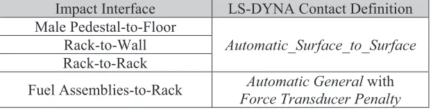
The LS-DYNA keyword file is read into LS-DYNA’s pre-processor, LS-PrePost, to define contact algorithms and input the time history for the seismic analysis. Various contact algorithms are defined to capture impact forces during the seismic analysis. A summary of the contact definitions used at each impact interface is provided in Table 2. Automatic_Surface_To_Surface contact requires the definition of the friction coefficient between contacting surfaces and is capable of capturing both frictional forces at interfaces in closed contact as well as impact forces whenever gaps between surfaces
are closed after leg uplift due to rack rocking (LS-DYNA® Theory Manual 2006, LS-DYNA® Keyword User’s Manual 2007). Since this particular contact definition has a significant impact on kinematic behaviour and energy dissipation, the proper behaviour of the Automatic_Surface_To_Surface contact definition is independently verified. The verification of the contact behaviour is discussed later in this paper. Sliding occurs at the Male Pedestal-to-Floor interface whenever the frictional force at this interface exceeds the product of the pedestal normal force and the defined static friction coefficient, while rocking occurs whenever overturning moments induced by the seismic motion are sufficient to raise the pedestal legs off of the defined floor surface. Vertical impacts between the male pedestal legs and the floor are captured whenever the rocking induced gap is re-closed due to the motion of the racks. Automatic General contact is used to define contact between the rack cells and fuel assemblies and to ensure that the fuel assemblies do not penetrate the surrounding rack structure. In order to obtain the Fuel Assembly-to-Rack impact forces from the RCFORC output file, Force_Transducer_Penalty contact is utilized to record the impact forces to the specified output file (LS-DYNA® Theory Manual 2006, LS-DYNA® Keyword User’s Manual 2007).
Table 2: Summary of LS-DYNA Contact Definitions at Impact Interfaces
Impact Interface LS-DYNA Contact Definition Male Pedestal-to-Floor
Automatic_Surface_to_Surface
Rack-to-Wall Rack-to-Rack
Fuel Assemblies-to-Rack Automatic General with
Force Transducer Penalty
Description of Analytical Approach
The analyses performed in this study consist of multiple spacing arrangements of two NFRs stored in a dry condition. Multiple spacing arrangements help to determine the optimal arrangement to preclude rack-to-rack and rack-to-wall impacts during seismic excitation. The friction coefficient defining the contact between the rack pedestal legs and the floor is another important model parameter since it can affect the overall kinematic behaviour of the racks. Higher friction coefficients can be expected to induce more rocking behaviour, while lower friction coefficients typically result in more sliding behaviour. Another variable in the analyses is the total amount of fuel assemblies located in the racks and their arrangement. The amount of fuel assemblies located in the racks has a large influence on the mass distribution and effect of damping of the overall system, which in turn has an influence on the overall dynamic response. The arrangement of the fuel assemblies within the rack has an impact on the center-of-mass of the rack. Table 3 provides a summary of the critical model parameters, which are important to consider in the seismic analysis of the fuel storage racks.
Table 3: Summary of Critical Model Parameters
Artificial Displacement Time Histories
Section 3.7.1 of NUREG-0800 (2014) provides requirements for Seismic Design Parameters used to evaluate the dynamic response of Seismic Category I Structures, Systems, and Components (SSCs). Of particular interest to the scope of this paper are the requirements for the Design Ground Motion, which includes one vertical and two horizontal spatial components. If time history analysis methods are used to determine the seismic response of SSCs, the time history inputs used in the analysis are permitted to be either real or artificial. For the analysis of the NFRs, artificial displacement time histories are generated for use as loading input to the detailed FE model. Generation of the artificial time histories is an iterative process, which ends whenever all acceptance criteria are satisfied. Figure 3 provides a flowchart summarizing the artificial time history generation process.
Figure 3. Artificial Time History Generation Process
Fuel Rack Mechanical Material Properties
In order to simulate the appropriate behaviour of the fuel racks under the applied seismic forces, the use of an appropriate material model is important. Therefore, non-linear (elastic-plastic) mechanical material properties are used for the fuel rack since permanent plastic deformations may occur within the duration of the analyses. ASME, Section VIII, Division 2, Annex 3.D (2008) is used to develop static true stress-strain curves. The elasticity portion of the stress-strain curve is excluded for the finite element analysis model to obtain the true stress vs. true plastic strain data, which is required in the plastic material model.
Fuel Assembly Properties
Design drawings specify the gap between the rack cells and the outer surface of the fuel assemblies; therefore, the beams used to model the fuel assemblies should have an outer surface matching the dimensions on the drawings. Only the cross-sectional properties of the fuel cladding within the fuel assemblies are considered when determining the stiffness properties of the beam elements. The cross-sectional area, A, of the beams is calculated using Equation 4:
*
+
*
d
d
t
+
n
A
02 02
24
,
,
&
-
(4)where:
d
o= outside diameter of fuel cladding
t
= thickness of fuel cladding
n
= number of fuel rods per fuel assembly
SeismicGround Motion Seed Files
Artificial Time History Generation
SRP Section 3.7.1 Acceptance Criteria Check
. Design Basis Response Spectra
. Target Power Spectral Density
Acceptance Criteria
Met? No
The moment of inertia,
I
, of the fuel cladding can then be calculated using Equation 5:
*
+
*
d
d
t
+
n
I
04 02
464
,
,
&
-
(5)A hollow square tube section is chosen to model the fuel assemblies, such that the cross-sectional area matches the value calculated in Equation 4 and the outer dimension, w, matches that of the actual fuel assembly. The required thickness of the hollow tube, thollow, to match the previously calculated
cross-sectional area, A, is determined using Equation 6:
2
2
A
w
w
t
hollow,
,
&
(6)The mass density, /, applied to the beam elements is calculated according to Equation 7:
ALg
w
t&
/
(7)where:
w
t= total weight of fuel assembly
L
= length of fuel assembly
g
= acceleration due to gravity
The moment of inertia in flexure for these hollow tubes does not match the value calculated in Equation 5; therefore, the modulus of elasticity of the beams is adjusted, so that the first fundamental frequency of the beam elements matches the expected frequency of the fuel assemblies. The expected fundamental frequency of the fuel assemblies is based on available test data. A modal analysis of a single fuel assembly is performed with boundary conditions corresponding to those in the detailed 3-D model and previously calculated beam properties. The modulus of elasticity is adjusted in an iterative process until the first fundamental frequency is within the expected range of the fuel assembly. This process of determining beam properties ensures that the dynamic behaviour of the fuel assemblies is captured and that the gap between the rack and beam elements is appropriately modelled to capture impacts between the beam elements and the surrounding rack structure.
Verification of Model Behavior
Proper modelling of the interface between the rack pedestals and floor is vital to capturing the kinematic behaviour of the racks during seismic events. Essential to this behaviour is capturing the frictional effects at this interface. In order to verify that LS-DYNA’s Automatic_Surface_to_Surface
contact definition is capable of modelling frictional effects, a simplified test model is run and compared to closed-form solutions for the sliding motion of a single mass subjected to a horizontal sinusoidal force. The single mass is modelled as a solid block located on a solid surface. The LS-DYNA results showed acceptable agreement with the closed-form solution with less than a 2.5% difference in the total energy calculated.
RESULTS AND DISCUSSION
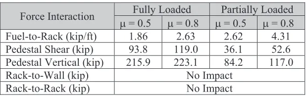
rack cells filled with fuel assemblies, while the partially loaded configuration has some rack cells left empty. The rack-to-rack and rack-to-wall spacing were kept constant during each of the runs summarized in Table 4.
Table 4: Summary of Force Interactions
Force Interaction Fully Loaded Partially Loaded
! = 0.5 ! = 0.8 ! = 0.5 ! = 0.8 Fuel-to-Rack (kip/ft) 1.86 2.63 2.62 4.31 Pedestal Shear (kip) 93.8 119.0 36.1 52.6 Pedestal Vertical (kip) 215.9 223.1 84.2 117.0
Rack-to-Wall (kip) No Impact
Rack-to-Rack (kip) No Impact
The spacing used in these runs resulted in no rack-to-wall and no rack-to-rack interactions for the given seismic time history. The spacing of the racks is an important parameter in fuel rack analyses and can be decreased to permit tighter rack storage arrangements (i.e. increase storage capacity) or increased to preclude anticipated rack-to-rack and rack-to-wall impacts. If the spacing of the racks is decreased and impacts are expected to occur, then it is important to ensure that the resulting impact forces do not exceed specified design limits for the fuel racks or fuel assemblies at particular locations. The results show that the pedestal shear and pedestal vertical force increase as the friction coefficient increases from 0.5 to 0.8 and also as the number of fuel assemblies increases. These increases in force interactions can be explained due to the increase in system mass from the partially loaded to fully loaded configuration, but the increase in friction coefficient is also expected to increase the rocking behaviour of the racks which would explain the increase in the pedestal vertical force. An increase in rocking behaviour would also explain the increase in the fuel-to-rack impacts for a friction coefficient of 0.8 since rocking behaviour results in in-phase motion of the fuel assemblies as the racks rock back and forth. The partially loaded configuration has higher fuel-to-rack impact forces, which can be explained by the fully loaded configuration having higher damping effects due to the additional mass and rattling of the added fuel assemblies.
Table 5 provides a summary of rack rocking for the LS-DYNA analysis runs. The maximum rocking angle is found by finding the maximum pedestal uplift and calculating the corresponding rocking angle using the distance between pedestal legs. The instability angle is calculated using the approach outlined in Section 7.1 of ASCE/SEI 43-05 (2005). The instability angle is the rocking angle required to initiate overturning of the rack. The uplift factor is equal to the tangent of the instability angle and is also equal to the minimum value calculated from Equation 2 and Equation 3.The results in Table 5 show an increase in rocking angle as the friction coefficient increases from 0.5 to 0.8 and also as the number of fuel assemblies in the rack increases. The increased rocking angle for the fully loaded configuration can be explained by the added mass of the fuel assemblies increasing the force required for the rack to slide, thus allowing for the rocking motion to develop. The results clearly show that the amount of rocking for the applied seismic time history is well below the amount required to cause overturning of the racks.
Table 5: Summary of Rack Rocking
Rack Rocking Parameter
Fully Loaded Partially Loaded
! = 0.8 ! = 0.8 ! = 0.5
Max Rocking Angle 1.35° 0.85° 0.76°
Instability Angle, ! 20.6° 10.6° 10.6°
Uplift Factor, tan(!) 0.38 0.19 0.19
by LS-DYNA includes kinetic, internal, damping, sliding, and hourglass energy. The internal energy includes the energy due to deformation of the system, including elastic strain energy as well as permanent deformations. The external work in the fuel rack analyses is the work performed due to the application of the displacement time history boundary conditions to the substructure (LS-DYNA® User’s Guide 2015). Since the initial energy is equal to zero in the analyses performed for this study, the total energy should equal the amount of external work. Figure 4 provides a plot of total energy versus external work. The energy imbalance for the results of this analysis can be defined as the difference between the total energy and the external work. The curves shown in Figure 4 are integrated over the entire time duration of the analysis to determine the amount of energy imbalance. The difference between the integrals of these two curves resulted in an energy imbalance of approximately 6% of the total energy. The LS-DYNA® User’s Guide (2015) states that artificial introduction of energy to the system will cause the total energy to exceed the sum of external work and initial energy, which is shown in Figure 4.
Figure 4. Plot of Total Energy versus External Work
A plot of energy imbalance can be obtained by subtracting the External Work curve from the Total Energy curve in Figure 4. Figure 5 provides a plot of the energy imbalance over the duration of an analysis, which closely resembles a plot of the Z-direction time history input. This similarity suggests that the energy imbalance is due to the calculation of energy for motion in the vertical direction. Further evaluation is needed to determine the exact cause of this imbalance.
(a) (b)
Figure 5. Plot of (a) Z-direction Time History Input and (b) Energy Imbalance
CONCLUSION
are multiple areas where additional work is needed. A summary of suggested topics for future work is summarized below.
Recommendations for future work:
. Further evaluation to determine the exact cause of the energy imbalance illustrated in Figure 5
. Determine approaches to efficiently incorporate fluid-structure interaction into the detailed 3-D model for submerged rack conditions
. Perform result comparisons between multiple rack models using simplified 3-D stick models and the more detailed 3-D modelling approach to determine relative costs and benefits
REFERENCES
American Society of Civil Engineers. (2005). ASCE/SEI 43-05: Seismic Design Criteria for Structures, Systems, and Components in Nuclear Facilities, Reston, VA, USA.
American Society of Mechanical Engineers. (2008). ASME Boiler and Pressure Vessel Code: Section VIII-Rules for Construction of Pressure Vessels, Division 2-Alternate Rules. New York, NY, USA. DeGrassi, G. (1992). NUREG/CR-5912 (BNL-NUREG-52335): Review of the Technical Basis and
Verification of Current Analysis Methods Used to Predict Seismic Response of Spent Fuel Storage Racks, Brookhaven National Laboratory, Upton, NY, USA.
GE-Hitachi Nuclear Energy Americas. (2010). “Dynamic, Load-Drop & Thermal-Hydraulic Analyses for ESBWR Fuel Racks,” Licensing Topical Report NEDO-33373-A, Rev. 5, NRC Docket Number: 0520010, Accession Number: ML102990226.
Livermore Software Technology Corporation. (2006). LS-DYNA® Theory Manual.
Livermore Software Technology Corporation. (2007). LS-DYNA® Keyword User’s Manual, Volume I, Version 971.
Livermore Software Technology Corporation. (2015). LS-DYNA® User’s Guide, http://www.dynasupport.com/tutorial/ls-dyna-users-guide.
Mitsubishi Heavy Industries. (2014). “Mechanical Analysis for US-APWR New and Spent Fuel Racks,” MUAP-07033NP, Revision 1, NRC Docket Number:
05200021,
Accession Number: ML14092A424.SAS IP, Inc. (2010). Element Reference, Release 13.0, ANSYS Mechanical APDL Documentation. U.S. Nuclear Regulatory Commission. (2014). Standard Review Plan for the Review of Safety Analysis
Reports for Nuclear Power Plants: LWR Edition (NUREG-0800) Section 3.7.1 Seismic Design Parameters, Rev. 4, Office of Nuclear Reactor Regulation, Washington, D.C., USA.
U.S. Nuclear Regulatory Commission. (2007). Standard Review Plan for the Review of Safety Analysis Reports for Nuclear Power Plants: LWR Edition (NUREG-0800) Section 9.1.2 New and Spent Fuel Storage, Rev. 4, Office of Nuclear Reactor Regulation, Washington, D.C., USA.
Westinghouse Electric Company. (2010). “AP1000 Standard COL Technical Report Submittal of APP-GW-GLR-033”, Revision 4 (TR54), NRC Docket Number: 0520006, Accession Number: ML101580475.