STRUCTURAL ANALYSIS AND
OPTIMIZATION OF THE HATCHED DOOR
OF THE SUBMARINE
Bhaskar Patil
1, Ravi G Lingannavar
2P.G. Student, Department of Mechanical Engineering, KLE’s College of Engineering and Technology, Belgaum, Karnataka, India1
Professor, Department of Mechanical Engineering, KLE’s College of Engineering and Technology, Belgaum, Karnataka, India2
Abstract: The submarine door mechanism is being analyzed for the identification of possible failure situations. An effort has also been made to give suggestions regarding the dimensions of the door model of submarine for further improvements. This will be helpful to the company to fabricate and also to show the results of the analysis to prospective customers. Purpose of the analysis is detect any flaws in the design stage can be identified and corrected in the analysis stage. Analysis stage acts as a prototype building stage where in the original is modeled and analyzed. The stress developed can be understood and suitably reduced by increasing or decreasing the dimensions, using a better material. The stress distribution can be understood and the maximum and minimum stress acting on the material can be estimated. In this project an effort has been made to carry out the analysis of “submarine door mechanism”. The project requires a basic knowledge of the analysis software and the working of the mechanism this is a complicated task, so to solve such problem COSMOS is the most preferred software tool, which has no boundary limit for analysis. Here Structural type of analysis carried out it includes a general overview of the submarine door mechanism CAD systems, FEM, the introduction to COSMOS. The final section of the documentation deals with the comparison of manual design results with the results obtained from the use of analysis software and if stresses result vary and factor of safety is high then we may require to go for optimization of particular part.
Keywords:Submarine, Submarine door, COSMOS, Structural Analysis, Optimization, CAD, SOM, FEM
I. INTRODUCTION
A. The basic parts of the Submarine Hull:
air by ridding it of carbon dioxide and impurities. Distilled Plants: Distilling plants purify saltwater to be used for the engine or for drinking water. The control room: It is the nerve center of the submarine. It contains the operational controls for all navigational, sonar, communications and weapons systems on the submarine. From here, the vessel's activities are directed. The torpedo room: It is where all torpedoes are stored and loaded into torpedo tubes to prepare them for launching.
B. Submarine Ballast Door Structure
The ballast door unit includes a base which is mounted on the submarine. The base is formed with two similar and opposite U-shaped struts which are connected at the end and to cross bar and respectively which are in turns mounted on the submarine. As shown in Fig. (a) Below
Fig. (a) Submarine Ballast Door
A ballast door is formed with similar and opposite members, one of which pivoted on the each of the struts but pivot pin for rotation around pivoted axis each of the frame is formed members is formed with projections which extends upward between the struts is connected to pressure operated actuator normally refer as sea water actuator includes cylinder pivoted on the struts by trunnions and plunger pivotally connected to the projections by pivot pin so that axial moment of plunger producing rotating of the members around pivot axis. The members also are provided with lateral extensions terminating in stop surface engageable with cross bar, when frame members are in their closed positions.
IISOFTWAREDESCRIPTION
A. About COSMOSS Software
The COSMOSS program has many finite element capabilities, ranging from a simple linear static analysis to a complex, non linear, transient analysis. A typical COSMOSS analysis has 3 distinct steps 1.Build the model. 2. Apply loads and obtain the solution.3.Review the results.
1. Build the model
element. 3. Defining Material Properties. Most element types require material properties. Depending of application material properties may be used . 4. creating the Model Geometry
The next step is generating a finite element model- nodes and elements –that adequately describe the model geometry. There are two methods to create the finite element model: solid modeling and direct generation.
2. Apply loads and obtain the solution.
In this step, the SOLUTION processor is used to define analysis type and analysis options, apply loads, specify load step options and initiate the finite element solution. 1 Define the analysis type and analysis options the analysis type is chosen based on the loading conditions and the response that is to be calculated. 2 Applying Loads The word “Loads” includesthe boundary conditions (constraints, supports or boundary field specifications) as well as other externally and internally applied loads. 3 Specifying Load Step Option Load step options are options that can be changed from load step to load step, such as number of sub steps, time at the end of a load step and output controls. 4 Initiating the Solution to initiate the solution calculations either of the following is used
Command: SOLVE GUI: Main Menu> Solution>Current LS>Main Menu> Solution> solution method
3. Review the results.
Once the solution has been calculated the COSMOSS postprocessors can be used to review the results.
B. Meshing:
Meshing is done automatically in the COSMOS software
III DESIGNANDANALYSISOFSUBMARINEHATCHEDDOOR
A. Material Selection.
The different material used for the analysis of the submarine hatched door are
Stainless steel- SS-304 Chromium 18%, Nickel 10%, Manganese 2%, Silicon 1%, Carbon 0.15% Sulphur 0.03%, Molybdenum. 0.045%
Stainless steel SS-316 Chromium 16% Nickel 14% Manganese 2% Silicon 1% Carbon 0.03% Sulphur 0.03% Molybdenum. 3%
B. Specifications
1) Material used for manufacturing the model: Stainless Steel 304
_ Chromium content of the Stainless steel: 0.18 _ Density=7.8×10⁻⁶ Kg/mm3
_ Ultimate tensile strength of the Stainless Steel=590 MPa _ Young’s modulus:1:97×105 MPa
_ Poisson’s ratio: 0.28
_ Load acting on the machine: 9810 Tons _ Maximum deflection: 0.83mm.
2) Material used for manufacturing the model: Stainless Steel 316
_ Chromium content of the Stainless steel: 0.16 _ Ultimate stress Stainless steel 316 =515 MPa Young’s modulus:1:97×105 MPa
_ Load acting on the machine: 9810 Tons _ Poisson’s ratio: 0.29
_ Density =8×10⁻⁶ Kg/mm3
C. Cad Model Of Submarine Hatched Door
Fig. (b) CAD model of Submarine Ballast Door
IV ANALYSIS RESULT SUBMARINE HATCHED DOOR STAINLESS STEEL 304
Submarine door cap whose maximum stress obtain is 56.6Mpa as shown in Fig. (c) below
Fig.(c) Submarine Door cap
Fig.(d) Piston Cylinder
The maximum stresses obtain are 172MPa in Submarine door Submachine assembly, as shown in Fig. (e) Below
Fig.(e) Submarine door machine sub assembly
The maximum stresses obtain are 271MPa in Submarine door base cylinder as shown in Fig.(f)
V THE ANALYSIS RESULT OF SUBMARINE HATCHED DOOR STAINLESS STEEL 316
The maximum stresses obtain are 284MPa in Submarine door base cylinder as shown in Fig. (g)
Fig.(g) Submarine door base cylinder sub assembly
The maximum stresses obtain are 171MPa Piston Cylinder, as shown in Fig. (h)
Fig.(h) Piston Cylinder
Fig. (i) Submarine door machine sub assembly
A) Comparison of Stresses obtain for Stainless Steel 304 and Stainless steel 316
Ultimate stress Stainless steel 304=590Mpa Ultimate stress Stainless steel 316=515Mpa
Table Comparison result of Stainless Steel 304 and 316
Name of Parts
Stainless steel 304
(Mpa)
Factor of safety
Stainless steel 316
(Mpa)
Factor of safety Machine
assembly
172 3.45 182 2.82 Piston
cylinder
159 3.71 171 3.01 Door cap 56 10.53 - -
Base cylinder
271 2.17 284 1.81
VI OPTIMIZATION OF DOOR CAP
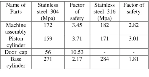
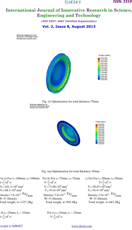
A) The initial weight of the door cap for total thickness 200mm is 1327.2Kg, hence we need to reduce the weight till factor of safety is reached within safe limits. For the first stage total thickness of the door cap is reduced to 150mm and its weight becomes 995.4Kg, now in next stage total thickness of the door cap is reduced to 100mm and its weight become 663.2Kg.Hence for the third stage total thickness of the door cap is reduced to 70mm and its weight becomes 468Kg.Now in the final stage total thickness of the door cap is reduced to 50mm, here factor of safety is 3.45 which is within safe limits. Hence its weight is 332Kg.
The various stages of optimization of the door cap as shown in below figures.
Fig. (j) Optimization for total thickness 150mm
Fig. (k) Optimization for total thickness 100mm
Fig. (l) Optimization for total thickness 70mm
Fig. (m) Optimization for total thickness 50mm
For a) For t1=100mm, t2=100mm For b) For t1=75mm, t2=75mm c) For For t1=50mm, t2=50mm
V=𝜋
4×d
2×t V=𝜋 4×d
2×t V=𝜋 4×d
2×t
V1=101.3×106 mm3 V1=71.06×106 mm3 V1=50.67×106 mm3
V2=68.3×10 6
mm3 V2=51.6×10 6
mm3 V2=34.4×10 6
mm3 Density=7.8×10⁻⁶ 𝐾𝑔 𝑚𝑚 Density=7.8×10⁻⁶ 𝐾𝑔 𝑚𝑚 Density=7.8×10⁻⁶ 𝐾𝑔 𝑚𝑚 W=V×Density W=V×Density W=V×Density
Total weight, w=1327.2Kg Total weight, w=995.4Kg Total weight, w=663.2Kg
For d) t1=35mm, t2 = 35mm For e) t1=25mm, t2 = 25mm
V=𝜋
4×d
2×t V=𝜋 4×d
V1=35.47×106 mm3 V1=25.33×106 mm3
V2=24.08×106 mm3 V2=17.20×106 mm3
Density=7.8×10⁻⁶ 𝐾𝑔 𝑚𝑚 Density=7.8×10⁻⁶ 𝐾𝑔 𝑚𝑚 Total weight, w=663.2Kg Total weight, w=332Kg
SI NO Total Thickness (mm) Factor of Safety Total Weight(Kg) 1 200 10.53 1327.2
2 150 7.25 995.4 3 100 5.21 663.2 4 70 4.14 468 5 50 3.45 332
VII CONCLUSION
The present work illustrates how stress analysis can be used in the design of Door panel of the Submarine. The technology has been successfully used in an industrial environment within short span of time and it is proved to be able to provide efficient component designs as this eliminates actual prototypes for analysis. However for better results the detailed test has to be carried out. The objective of the present study is to investigate the stresses acting machine assembly of submarine door panel. In this study, the effects of stresses in submarine door panel is observed when submarine door is in closed position. Parametric studies were done to examine the effects of stress on the different machine assembly parts, based on the results of finite element predictions and by the calculations of the stress analysis approach, From the load cases the maximum stress is compared with yield stress and ultimate stress of Stainless Steel 302 alloy. The obtained magnitudes of maximum stress are less than the yield stress and ultimate stress so we conclude that material in elastic limit and not yet started yielding.In the project work the following is carried out, 1) The standard dimensioned machine assembly parts are considered for the stress analysis.2) Loads and boundary conditions are accurately simulated to obtain the realistic loading conditions.3) Finite element approach is used for the stress analysis.4) The Cosmos software is used for analysis purpose.5) The theoretical validation of the each assembly parts is carried out The factor of safety of each part is determined and the factor of safety of door cap is found to be very high. 6) The door cap machine part is considered for optimization by reducing the material then factor of safety and maximum stresses are found out. 7) Then obtained magnitudes of maximum stress are less than the yield stress and ultimate stress so we conclude that material in elastic limit and not yet started yielding. 8) Maximum stress is observed at rod operating the door segment and hollow base cylinder.
REFERENCES
[1], R.S. Khurmi &,J.K.Gupta, “Machine Design Text Book”,S Chand Publication. 14th Edition, pp 233-239, 2009.
[2]. Dr. K. Lingaiah “Machine Design Data Handbook”,McGraw-Hill Professional Vol. I; 4th Edition, pp 8.3-8.4, 2006.
[3] Sjogren J, Celsing C-G, Olsson K-A, Levander C-G, “Hellbrat S-E Swedish development of MCMV –hull design and production”. In Proceeding of the international Symposium on Mine Warfare vessels and Systems, London,Vol 7, pp 21-25, 1984.
[4]Robert ML, Smith CS. “Design of submarine structure”. Proceedings of the Undersea Defence Conference, London Vol 6. pp.217-225, 1988. [5] Smith CS, Murphy P., “Response of steel superstructure to blast loading- theory and experiment”. Advances in marine structures -2. London: Elsevier; Vol.12. pp. 392-415, 1991.
[6] Capt. H.A., “The Influence of the USS Albacore on Submarine Design”. International Symposium on Naval Submarines Warship, Vol 11 pp.94-107,1993.
[7]Kuiteinikov, A.V. Khudiakov and Moore K. J.“Emerging Technology and Submarines of the 21st Century”. International Symposium on Naval Submarines Vol 10 pp 66-70, 1993.
[8] Antonov, A.M., Dronov, B.F. and Kuteinokov A.V., “Soviet and Russian Attack Submarines: Evolution of a Concept, Paper 2”, International Symposium. on Naval Submarines, RINA, London. Vol 6, pp 32-37,1993.
[9] Andrews, D.J. “A new Approach to Submarine Concept Design,Paper 19”. International Symposium on Naval Submarines, Warship i96, RINA, London Vol 18, pp 45-58,1996.