ISSN: 2319-8753
I
nternational
J
ournal of
I
nnovative
R
esearch in
S
cience,
E
ngineering and
T
echnology
(An ISO 3297: 2007 Certified Organization)
Vol. 3, Issue 7, July 2014
Mathematical Modeling and Computer Simulation
of Particle Gradient Distribution in a Vertical
Centrifugally Cast Functionally Gradient Composite
Abdul Samad P.A.
1, Sandeep K.
2, Dr. Shalij P. R.
31Associate Professor, Department of Mechanical Engineering, Govt. Engineering College, Trichur, Kerala, India 2Post
Graduate Student, Department of Mechanical Engineering, Govt. Engineering College, Trichur, Kerala, India
3Associate Professor, Department of Production Engineering., Govt. Engineering College, Trichur, Kerala, India
ABSTRACT
:
Ceramic particles suspended in Aluminum melts for vertical centrifugal casting of Functionally Gradient Composite (FGC) have been studied. Force balance on ceramic particles is formulated and motion of ceramic particles in viscous molten metal under centrifugal force and drags force has been modeled. Effects of solidification were incorporated. MATLAB is used to simulate the process of gradient composition formation in vertical centrifugal casting of Aluminum Silicon Carbide composite. Effect of various parameters like mold rotational speed, solidification rate and initial partial fraction of particle on segregation of particle is examined.KEYWORDS: Centrifugal Casting, Functionally Gradient Composite, Particle Segregation, Aluminum Silicon Carbide Composite
I. INTRODUCTION
Functionally gradient materials (FGM) are characterized by continuous and smooth variations in compositions and/or microstructure so as to meet functional performance requirements that vary with location within a part. Among various FGMs, metal-ceramic FGMs, also called functionally gradient composites (FGC) are of great practical interest. FGCs are epitomized by gradual compositional variation from metal concentrated region at one area to ceramic concentrated region at another. This leads to mechanical physical and/or chemical properties across the thickness. The advantage is minimized stress concentration at the interface of dissimilar materials.FGCs are finding applications in aggressive environments with steep temperature gradients such as rocket nozzles, thermal barrier coatings, turbine component etc. It has also found its application in some automobile components.
ISSN: 2319-8753
I
nternational
J
ournal of
I
nnovative
R
esearch in
S
cience,
E
ngineering and
T
echnology
(An ISO 3297: 2007 Certified Organization)
Vol. 3, Issue 7, July 2014
II. RELATED WORK
P. Samba Siva Raju et al.[1] proposed a mathematical model to find the particle motion in centrifugal casting of metal ceramic composite. The proposed model is simulated and results show that rotation speed has good effect over the gradient formation. Prem E J Babu et al.[2] described in their paper that when centrifugal force is applied on casting, it allows control of the particle distribution in a metal matrix during solidification and becomes an important and fruitful technology for production of cast parts with graded structures and properties. Segregation of the solid particles dispersed in liquid rotating slurry occurs owing to centrifugal force. Particles are moved either to the outer or the inner part of rotating mould because of their density difference with the melt.
There are different approaches for the description of the physical interactions, which take place in this complex of phenomena characterizing centrifugal casting of particle reinforced composites. Almost all models existing at present are one-dimensional because of simplicity and the fact that centrifugal acceleration is much greater than gravity [3,4]. Almost all studies till date uses a simple first degree differential equation as dynamic equation except the model by Prem E. J. Babu, T.P.D. Rajan, S. Savithri, U.T.S. Pillai and B.C. Pai [2]. The dynamic equation is essentially a second order differential equation because of the centrifugal acceleration. But The thickness of the particle rich zone at the two ends of a casting (top and bottom, or the front and rear parts of a centrifugally cast cylinder) is very often larger than the same zone in the central part of casting in case of a horizontal centrifugal casting [3]. So the case is essentially two dimensional in horizontal centrifugal casting. Here we are considering vertical centrifugal casting which leads to a one dimensional problem.
III. MODELING OF FORCES ACTING ON PARTICLE
Particles in a metal molt will be acted on by centrifugal, gravity and drag forces and the interaction between the particle and the interface of the particle movement (solidification front). The following assumptions are made for modeling:
Ceramic particle is spherical in shape
The pouring melt is having uniform distribution of particle suspended in molten metal
II.A. Centrifugal Force
During centrifugal casting, particle segregation occurs owing to difference in densities between the molten metal and the particles. Assuming spherical particles, the total centrifugal force is given by
FC = mω2 r = (4/3)π Rp3 (ρp –ρAl) ω2 r
r is the radial distance of the particle from axis of rotation, N is the rpm of rotation, Rp is the radius of particle.
II.B Drag force
In the case of flow over a sphere, both friction drag and pressure drag (form drag) contribute to total drag. Stokes reported that for a symmetric flow field with small velocities (Re < 0.1), the dominant force on the sphere is viscous and the inertial term in the momentum equation can thus be neglected. The expression given by Stokes is
FD = 6 π Rp μvp =6 π Rp μ
ISSN: 2319-8753
I
nternational
J
ournal of
I
nnovative
R
esearch in
S
cience,
E
ngineering and
T
echnology
(An ISO 3297: 2007 Certified Organization)
Vol. 3, Issue 7, July 2014 II.C. Repulsive Force by Solidification Front
The repulsive force offered by solidification front becomes prominent only when the particle approaches very close to the solidification front, where the metal transforms to mushy form. It is given by [2]
FS = 2 π Rp ∆ᵞ0[a0/(a0+d)]2 Where d= distance between solidification front and particle
∆ᵞ0
=
ᵞPS
-
ᵞPL
-
ᵞSL
Young’s equation is given by
ᵞPL
=
ᵞPV
-Cos
ѲᵞLV
Also by Newman’s equation ,
ᵞPL
=
[
ᵞPV
0.5-
ᵞLV
0.5]/[1-k(
ᵞPV
x
ᵞLV
)
0.5]
The radial forces acting on SiC particle can be represented as shown in figure 1. We can see that FC is radially outwards, FD and FS are radially inwards. As the magniture of FC is much greater than FD + FS , itwill move towards the solidification front.
Figure 1: Forces Acting on Sic Particles
Thus the dynamic equation of particle is given by
4/3 π Rp3 ρp(d2r/dt2) = FC-FS-FD
We are considering a cylindrical mold of diameter 100mm. In order to understand the particle distribution up to the centre of rotation (centre of casting); we are casting a solid cylinder. This consideration eliminates the necessity of high rotating speeds so that we can get thicker particle rich regions resulting in more functionally gradient materials.
When the particle touches the wall, it stops and the position of particle at this moment is the final position of particle. We have to find final position of all 10 particles mentioned above from 0.005 to 0.05. Particle at 0 will not move radially, as it will not experience any centrifugal force.
Fc FD
FS
ISSN: 2319-8753
I
nternational
J
ournal of
I
nnovative
R
esearch in
S
cience,
E
ngineering and
T
echnology
(An ISO 3297: 2007 Certified Organization)
Vol. 3, Issue 7, July 2014
0 0.005 0.01 0.015 0.02 0.025 0.03 0.035 0.04 0.045 Initial position of particles (meter)
Figure 2: Initial Distribution of Particles Which Are Under Consideration
III. RESULTS AND DISCUSSION
III.A. Effect of mold rotation speed
Concentration gradient at mold rotation speeds of 400rpm, 800rpm and 1200rpm are simulated in MATLAB and results are plotted as below. Other parameters are particle volume fraction of 0.1, solidification rate of 10 microns/s, particle size of 40 microns.
Figure 3: Concentration Vs Radial Position at Various Mold Rotation Speeds
Mold wall Solidification direction
ISSN: 2319-8753
I
nternational
J
ournal of
I
nnovative
R
esearch in
S
cience,
E
ngineering and
T
echnology
(An ISO 3297: 2007 Certified Organization)
Vol. 3, Issue 7, July 2014
that the process offers a good control over the distribution of SiC particles in Al matrix. This is contributed by the density ratio of Al and SiC. So Al-SiC composition is very suitable for molding functionally gradient parts.
While looking at the concentration of Si-C at various positions radially, we can see that at 1200 rpm, it goes too high at periphery, and almost zero near the centre up to 15mm from centre. More than 35% concentration of the SiC in wt/wt will result in poor micro structure. Al matrix will be weak and property of such a part may be undesirable. At 800 rpm concentration lies well under 35% , which is allowable. Further looking at the values of concentration, we can see that at around 10mm depth from periphery it reaches the 10% concentration and further down to almost 0% around 0.01 from centre. On looking at the graph of 400 rpm, concentration varies more in a linear way compared to higher rpm. Also the maximum concentration at periphery is only 15% . 10mm away from centre it comes to 3.5%.
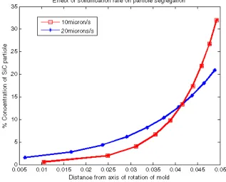
III.B. Effect of Solidification Rate
Solidification rate, varies with the type of mold material, number of layers of mold, convection type, shape of the mold etc. For cylindrical mold the rate of solidification is assumed to be constant. It may vary from 9 microns/s to 70 microns/s radially inwards, starting from outer surface of the casting. In order to understand the effect of solidification rate, we are considering 2 solidification rates: 10 microns/s and 20 microns/s. Plot shown below is at 800 rpm mold rotation speed, other parameters same as previous plot.
Figure 04: Effect Of Solidification On Particle Segregation
ISSN: 2319-8753
I
nternational
J
ournal of
I
nnovative
R
esearch in
S
cience,
E
ngineering and
T
echnology
(An ISO 3297: 2007 Certified Organization)
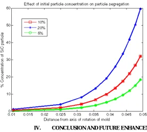
Vol. 3, Issue 7, July 2014 III.C. Initial Partial Fraction of Particle in Melt
Initial partial fraction affects viscosity of the melt, thus influence on drag force experienced by each individual particle. The expected result is lowering the segregation of particle. Also it gives rise to overall concentration increase, which may be experienced throughout the thickness of casting.
From figure 5 we can observe that, effect of drag force variation is very small as compared to the overall particle concentration increase. So we can say that as initial particle concentration doubles, the overall concentration also gets almost doubled. Effect of viscosity change may be neglected. Other parameters are 800 rpm mold rotation speed, 40 microns particle size, 10 microns/s solidification rate.
Figure 5: Effect of Initial Particle Concentration in Melt on Particle Segregation
IV. CONCLUSION AND FUTURE ENHANCEMENT
ISSN: 2319-8753
I
nternational
J
ournal of
I
nnovative
R
esearch in
S
cience,
E
ngineering and
T
echnology
(An ISO 3297: 2007 Certified Organization)
Vol. 3, Issue 7, July 2014
[3] Eduardo Trejo University of Birmingham , UK , Centrifugal Casting of an Aluminium Alloy, Ph.D Thesis Repost, Oct 2011.
[4] Nicholas Zabaras, Lijian Tan, Cornell University, Ithaca, USA MCWASP , Modeling of microstructure evolution in the solidification of multi-component alloys using level set methods, , Modeling of Casting, Welding and Advanced Solidifcation Processes XI, Dec 2011.
[5] Madhusudhan, Narendranath S, G C Mohan Kumar, Nitte Meenakshi Institute of Technology, Yelahanka, Bangalore, Properties of Centrifugal Casting at Different Rotational Speeds of the Die, International Journal of Emerging Technology and Advanced Engineering, Volume 3, Issue 1, January 2013.
[7] Prem E. J. Babu, T.P.D. Rajan, S. Savithri, U.T.S. Pillai and B.C. Pai Regional Research Laboratory, Trivandrum, India, Numerical simulation of macrostructure formation in centrifugal casting of particle reinforced metal matrix composites. Part 1: model description, International Symposium of Research Students on Materials Science and Engineering, Chennai, India, December 20-22, 2004.
APPENDIX
Assumed Data
ρp= Particle material (SiC) density =2360 Kg/m3 ρAl= Density of molten Al = 2360 Kg/m3 D= Inner diameter of the mold = 0.1m Rp= Radius of SiC particle = 40x10-3m
μ0= Viscosity of molten Al at 700oC =2x10⁻³PaS Interface energies
ᵞPV = 1.844J/m2, ᵞLV = 0.84 J/m2, ᵞSV = 0.98 J/m2 a0= atomic distance of Al crystal= 3x10⁻⁸m