AXE Operation & Maintenance Platform
IO-System
Ericsson Telecom AB 1996, Stockholm, SwedenAll rights reserved. No part of this document may be reproduced in any form without the written permission of the copyright holder.
Target Audience
This book is preliminary intended to be used as a course manual in the Ericsson Operation and Maintenance training program. The book is a training document and is not to be considered as a specification of any Ericsson language or system.
Identification
EN/LZT 101 105/3 R1A
Responsibility Training Supply
Table of Contents
1. Introduction
1
1.1 Module Objectives . . . 1
1.2 General . . . 1
2. Configuration of IOG 11
and Hardware Structure
3
2.1 Chapter Objectives . . . 32.2 Configuration of IOG11 . . . 3
2.2.1 SP-based IO Systems . . . 3
2.2.2 Input/Output Functions . . . 4
2.2.3 IO Device Functions and Characteristics. . . 9
2.3 Subsystems in IOG11 . . . 12
2.3.1 Support Processor Subsystem (SPS) . . . 12
2.3.2 Man-machine Communication Subsystem (MCS) . . . 14
2.3.3 File Management Subsystem (FMS) . . . 16
2.3.4 Data Communication Subsystem (DCS) . . . 18
2.4 Hardware Structure . . . 19
2.4.1 Introduction . . . 19
2.4.2 Different SP-Based IO Systems. . . 19
2.4.3 Magnetic Tape Group (MTG 10) . . . 22
2.4.4 IOG 11B. . . 24
2.4.5 IOG 11B5. . . 35
2.4.6 EXternal RANGing (EXRANG) . . . 37
2.4.7 IOG 11C. . . 39
2.4.8 IOG 11C5. . . 45
2.4.9 LEDs and Buttons . . . 47
2.4.10 1.05 GBytes Hard Disk . . . 49
3. Command and File Handling
53
3.1 Chapter Objectives . . . 53
3.2 IOG 11 Command Handling . . . 54
3.2.1 Entry Commands . . . 56
3.2.2 Subcommands. . . 58
3.2.3 Local Mode and CPT Commands . . . 60
3.3 Status of IOG 11 Units. . . 62
3.3.1 RPA State . . . 62
3.3.2 Node Configuration Status. . . 63
3.3.3 Line Unit Status . . . 66
3.3.4 Port Data . . . 67
3.3.5 MCS Device Data . . . 69
3.3.6 Blocking and Deblocking . . . 71
3.4 File Handling . . . 72
3.4.1 FMS Concepts . . . 72
3.4.2 Functions of FMS. . . 75
3.4.3 The Software of FMS . . . 77
3.4.4 Mass-Storage Media . . . 77
3.4.5 Volumes on Floppy Disk, Optical Disk and Tape . . . 80
3.4.6 Volumes on Hard Disk . . . 82
3.4.7 File Parameters . . . 83
3.4.8 Creation of a File . . . 84
3.4.9 Printing File Attributes . . . 86
3.4.10 Removal of a File . . . 86
3.4.11 Copying of Files . . . 86
3.4.12 Command Files . . . 88
3.5 File Process Utility . . . 90
3.5.1 General . . . 90
3.5.2 Manual Transfer over Data Link . . . 91
3.5.3 Automatic Transfer over Data Link . . . 91
3.5.4 Output on Magnetic Tape. . . 96
3.5.5 Direct File Output. . . 97
3.6 Charging Output . . . 98
3.7 The MCS Transaction Log . . . 101
4. System Backup Handling
105
4.1 Chapter Objectives . . . 105
4.2 Backup Functions of the CP . . . 105
4.2.1 Manual Dumps. . . 105
4.2.2 Automatic Dumps. . . 106
4.2.3 The CP Backup File . . . 107
4.2.4 Backup Handling (APZ P1) . . . 109
4.2.5 Command Log (APZ P1) . . . 112
4.2.6 Backup Handling (APZ P2) . . . 114
4.2.7 Command Log (APZ P2) . . . 118
4.3 Conversion of System Backup Files . . . 119
4.4 Backup of the SP . . . 120
4.5 Loading of APZ . . . 121
4.5.1 The APZ Subsystems . . . 121
4.5.2 States of the two CP sides. . . 123
4.5.3 CPT System. . . 124
4.5.4 Separation . . . 124
4.5.5 Loading of APZ 211 . . . 127
4.5.6 Loading of APZ 212 . . . 128
1. Introduction
1.1 Module Objectives
Figure 1.1 Module objectives
1.2 General
This module is valid for the control systems and IO systems available in the following APZ Source Systems:
APZ P1:
•
APZ 212 10 R2•
APZ 212 02 R3•
APZ 211 10 R2•
APZ 211 02 R7Module Objectives
After completing this module the participant will be able to:
• Describe the configuration of IOG11
• Name the basic concepts of the four subsystems in IOG11, i.e. SPS, FMS, MCS and DCS.
• Explain the purpose of entry commands in IOG11.
• Describe briefly the different statuses and states of the nodes in a node pair.
• Use IOG11 commands for creating, copying, deleting, writing to, reading the contents of and executing files.
• Explain the purpose of the File Process Utility function (FPU) giving the types of data that are normally transferred by this function.
• Use the FPU function to transfer files from hard disk to a magnetic tape or via an already existing data link.
• Set up logging conditions for the MCS Transaction Log and execute searching in the log file.
APZ P2:
•
APZ 211 11 R1•
APZ 212 11 R1•
APZ 212 03 R1The processors to be used for AXE Local 12.3 will all have to run with the APZ P2 operating system.
The APZ P1 versions can be updated to APZ P2 by changing the PROM stored firmware.
For APZ P2, the IO system IO-P2 has been introduced. Both processor and storage capacity have been improved in comparison with IO-P1. However, the IO system can easily be updated from IO-P1 to IO-P2 for both APZ P1 and APZ P2.
The most relevant differences between APZ P1 and APZ P2 concerning the IO system are the use of the Command Log and reloading of CP backups.
2. Configuration of IOG 11
and Hardware Structure
2.1 Chapter Objectives
Figure 2.1
Chapter objectives
2.2 Configuration of IOG11
2.2.1 SP-based IO Systems
This book provides a description of the Input/Output system IOG 11 as suited to the work of the operation and maintenance technician.
IOG 11 belongs to what is normally called SP-based IO Systems. SP is an abbreviation for Support Processor, the separate processor that controls the IO system.
Several variants of SP-based IO Systems exist today:
IOG 11A, IOG 11B, IOG 11C, IOG 11B5, IOG 11C5 and IOMC.
Chapter Objectives
After completing this chapter the participant will be able to:
• Describe the main tasks of the IO System.
• Describe the configuration of an IOG11.
• Explain the concepts Node, Link and SPG.
• Relate the main use of Hard Disks, Floppy Disks, Magnetic Tapes and Optical Disks.
• Relate the main use of Data Links.
• Name the four subsystems incorporated in IOG11 and give the names of the hardware units that are included in each subsystem.
• Briefly account for the main differences between the IO variants IOG 11B/B5 and IOG 11C/C5.
• Name the different magazines that are included in IOG 11 and know where the IO devices are connected.
• Describe the units that constitute an MTG 10.
This document will include such topics as:
•
the IO functions and devices•
the hardware configuration•
the subsystems that are included in the IO group•
the connection to the Central Processor, CP•
command handling•
the treatment of files on magnetic storage media•
general operation procedures for IOG 11.Examples will be given of
•
file handling•
charging outputs•
dumping and system backup handling (conversion)•
logging functions•
loading of APZ during normal operation.Initial loading and maintenance of the CP will be covered in the course LZU 108 1453, AXE 10 Hardware Maintenance.
2.2.2 Input/Output Functions
The IO functions of IOG 11 reflect the tasks to be performed by the equip-ment. These tasks can be generally described as follows:
•
handling of data (binary or alphanumeric) to and from theCP. IOG 11 is the IO interface to the world outside an AXE exchange.
•
secondary storage (mass storage) of information on magneticmedia, e.g. hard disk, flexible disk, mag-netic tape and optical disk.
The above mentioned data handling can consist of the transportation of either alphanumeric information - e.g. commands and printouts sent to or from a terminal or over a data link - or of data stored in files on the mag-netic media. Note that the information stored in a file can be either binary information e.g. backup data, or alphanumeric data e.g. commands in a command file.
From the above considerations we see that the hardware of IOG 11 must contain the following components:
•
a processor with the necessary software to control the different units, diagnose IO faults and to communicate with the CP•
external mass storage devices (hard disks, floppy disks, magnetic tapes and optical disks)•
data links for both high speed and low speed traffic using both asyn-chronous and synasyn-chronous transfer•
alphanumeric terminals for man-machine communication.As well as the above units, the IO Group is also required to provide alarm information on the alarm panel and alarm printer.
The alarm information concerns both internal alarms from APT, APZ and the IOG itself, as well as external alarms (temperature, humidity, door control, etc).
The IOG must also contain:
•
an alarm printer - i.e. an alphanumeric terminal to which alarm print-outs are automatically routed. A separate alarm printer is normally defined (but any alphanumeric terminal and slave printer can be used.)•
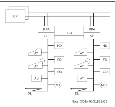
an alarm interface to which alarm panels and external alarm sensors are connected.Figure 2.2
Example of an IOG11
Figure 2.2 shows the standard IOG 11 configuration for the products IOG 11B/B5 and IOG 11C/C5. The differences between the variants will be covered later.
The interface to the Regional Processor Bus is called the RP Bus Adapter
(RPA).
The RPA is basically a regional processor, with its own unique address, that is adapted to the task of helping the main processor in IOG 11 in its communication with the CP.
The control unit in IOG 11 is a processor called the Support Processor, or
SP for short.
The IOG11B/C is based upon the Motorola 68010 (CP-3) processor, intro-duced with APZ 212/211 10 R1, APZ 212 02 R2 and APZ 211 02 R6. The IOG 11B5/C5 is based upon the Motorola 68030 (CP-5) processor, intro-duced with APZ P2.
The SP contains a considerable amount of software and has an internal memory of max 12 megabytes (Mb) for IOG 11B/C and 32 Mb for IOG 11B5/C5. Furthermore, a large amount of data required by the SP is
DL DL
ICB CP
RPA
SP
HD
AT
AT
OD
ALI
MT MT
AT
OD AT
AT
HD RPA
SP
FD FD
The CP also contains a fairly large amount of software used by IOG 11. We will look at this later on when the different subsystems of IOG 11 are examined.
As can be seen, the RPA and SP are duplicated in the standard IOG 11 configuration. This is done as a precaution against faults (hardware or soft-ware) arising in one of the SPs.
The two SPs are connected by a bus called the Inter Computer Bus (ICB). The ICB allows data to be transferred between the two SPs. It is an 8 bit parallel bus and carries data at a maximum nominal rate of 115 kilobytes/s (kb/s).
The SP is often called Node (as it can be used as a node in a packet switched data network).
The nodes in the duplicated configuration shown above are designated
Node A and Node B.
The RPA is also called Link, as it is a link between the SP and the CP.
The IO devices shown in figure 2.2 are as follows:
•
AT Alphanumeric Terminal•
ALI Alarm Interface•
DL Data Link•
HD Hard Disk drive•
FD Floppy Disk drive•
OD Optical Disk drive•
MT Magnetic Tape driveThe IO devices will be covered in detail in the next section.
An IOG 11 as described above - with two nodes each controlling a number of IO devices - is called a Support Processor Group, SPG.
An SPG can consist of one unduplicated node, but this is very unusual with IOG 11A, IOG 11B,and IOG 11C. The product IOMC has a very compact design and consists of one single node. It is used for very small exchanges.
.
Figure 2.3
A Support Processor Group (SPG)
It is possible to connect up to four SPGs to the CP, as is shown in figure 2.4.
Figure 2.4
Four SPGs connected to the RP bus
As can be seen from the figure, each SPG is numbered, with the first SPG being designated SPG-0.
Most AXE exchanges with IOG 11 will require just one SPG, i.e. SPG-0, whereas exchanges requiring very large amounts of output data storage and transfer would require two or three SPGs.
SPG-1, SPG-2, and SPG-3 provide basically separate processors for hand-ling such data. They relieve the workload of the SPs in SPG-0 which can be used to handle the alphanumeric IO devices and alarms.
CP-A
CP-B
RPB-A
RPB-B
RPA
SP
ICB
SPG
RPA
SP
ICB
SPG-0
ICB
SPG-1
ICB
SPG-2
ICB
SPG-3
RPB-A RPB-B CP
SP SP SP SP
SP SP
The data stored in these SPGs is normally toll ticketing data and statistical data which is subsequently transferred to remote destinations on high speed data links or transferred to tape.
We will look more at this later when we examine the different possible IOG configurations.
In SPG-0, the link at Node A is designated Link 0 and at Node B is desig-nated Link 1.
Link 0 has RP address RP-1 and Link 1 has RP address RP-4.
In the other SPGs the corresponding designations are:
•
Link 2 (RP-5) and Link 3 (RP-6)•
Link 4 (RP-7) and Link 5 (RP-8)•
Link 6 (RP-9) and Link 7 (RP-10)2.2.3 IO Device Functions and Characteristics
The IO devices that we use in IOG 11 have already been mentioned. They will now be examined in more detail.
Alphanumeric Terminal (AT) is the device used for man machine
commu-nication. The ATs are used for sending commands and receiving printouts.
An AT can be any type of asynchronous terminal, normally a personal computer (PC), a display handler or typewriter. It can also be a line printer, e.g. the alarm printer is also an AT, as shown in figure 2.5.
Figure 2.5 IO devices
Alarm Interface (ALI) is the interface to which the alarm panels and
exter-nal alarm sensors are connected. Exterexter-nal alarm information is sent to the SP, and internal and external alarm information sent to the alarm panels, via this interface.
As we shall see when we look at the hardware configuration, the ALI is connected to the SP in exactly the same manner as an AT device. It is regarded as being an AT device and is defined in the data as such.
It should be noticed from figure 2.2 that in the standard configuration the ALI is usually only found in one IOG 11 side - Node A.
In the SP and CP reference packages, four AT devices are predefined in the initial data:
•
AT-0 normal AT for use when SPG has been started•
AT-1 the alarm interface ALI•
AT-4 normal AT for use once the IOG has been started (maintenance)•
AT-5 as AT-4 (or ALI in node if this exists)If more AT devices are needed they have to be defined by commands and new hardware has to be installed if necessary. Connecting new AT devices is covered in the course LZU 108 1452, AXE 10 Operation Handling.
DL
ICB CP
HD
OD
MT ALI
AT AT
RPA
SP
Hard Disk (HD) is a mass storage unit type Winchester disk drive
consis-ting of a number of rapidly rotaconsis-ting disks with magnetic surfaces.
The number of disks per drive varies between the different IOG 11 variants leading to different storage capacities, as given below.
Per Hard Disk (HD): Unformatted Formatted
IOG 11B/B5, IOG 11C/C5 382 Mb 300 Mb 1.27 Gb 1.05 Gb
The HD units are used to store a backup of the SP programs and data, a backup of the CP software, Command Log and Transaction Log functions, charging output data and statistical data.
With regard to the hard disks, it should be noted that the CP is always loaded or reloaded from a HD unit.
Floppy Disk (FD) is a mass storage unit for replacable diskettes. The
dis-kette size is 5 1/4” and storage capacity is 1.2 Mb when formatted.
Diskettes are used as moveable media. Examples of their use are the loa-ding of SP software at initial start of IOG 11 and the loaloa-ding of command files.
The CP reference dump can also be copied to hard disk from diskettes prior to initial loading of the CP. However, magnetic tape is normally more convenient for this due to the large number of diskettes otherwise required.
Magnetic Tape (MT) can be used for certain applications where a
move-able medium that can store large amounts of data is required.
It is normally used at initial loading of the CP reference when the
exchange is started for the first time. The reference is copied from the tape to hard disk before loading. Backups of the CP software can also be stored on magnetic tape (max 55 Mb). The required backup file on hard disk must be copied to the tape for this purpose.
MT (max 35 Mb) is also used as a storage for charging data such as toll ticketing output. The data is first output to hard disk and then transferred to tape.
MT can also be used as a manual backup function for a data link during transfer of charging data, or for storing charging data from Operator Subsystem (OPS) which is first output to HD and then transferred to tape or data link.
Optical Disk (OD) (the complete name is Optomagnetic Disk) is a
mass-storage unit for replaceable disks. The mass-storage capacity of the 5 1/4” disk is 2x297 Mb, when formatted and 2x325 Mb when unformatted.
The OD is readable, writable and rewritable. Writing and rewriting is realized by using the magnetic material on the disk.
The handling of the OD is important, therefore the Operational Instruction should always be followed.
Data Links (DL) can be used for the connection of remote terminals at an
OMC, and for the transmission of data - e.g charging output or statistics - to a processing centre.
2.3 Subsystems in IOG11
The following subsystems belong to IOG 11:
•
SPS Support Processor Subsystem•
MCS Man-machine Communication Subsystem•
FMS File Management Subsystem•
DCS Data Communication SubsystemThe hardware of each subsystem is shown in figure 2.6.
Figure 2.6.
The subsystems of IOG 11
2.3.1 Support Processor Subsystem (SPS)
General
SPS implements the program control of the Support Processor, the SP-CP communication function and maintenance functions for the SP and RPA.
DL
MCS
FMS
DCS
AT
ALI AT
HD
OD
MT
ICB
SPS
CP
RPA
SP
SPS consists of the following components:
•
the Support Processors (SPs) with their operating system•
the Regional Processor bus Adapters (RPAs)•
software for communication between CP and SP•
software for operation and maintenance functions for the SPG.SPS interworks with the following subsystems:
•
Central Processor Subsystem (CPS)•
Regional Processor Subsystem (RPS)•
MCS, FMS, DCS•
Several APT subsystems, for example Statistics and Traffic Measure-ment Subsystem (STS) and Remote MeasureMeasure-ment Subsystem (RMS). (These two subsystems have their software loaded into the SP.)The SP is an Ericsson designed real time computer called APN 167. It is based on the Motorola M68000 family.
At loading or reloading of an SP, a PROM-stored bootstrap is used to initiate loading of the SP operating system and software into the primary memory of the SP from the hard disk. During start up of IOG 11 the soft-ware is first transferred to the hard disk from a number of diskettes.
The RPA is the interface unit between the RP bus and the SP, see figure 2.7. It transfers and receives messages to and from the CP.
Figure 2.7
The hardware of SPS
RPA works as a Slave to the SP which has the Master functions.
It consists basically of a microprocessor with its own operating system and software stored in a PROM memory.
RPB-A RPB-B
CP
RPA
SP
The Bus Network Adapter (BNA) is the interface to the ICB in each node.
The Software of SPS
The SPS software is situated in the CP, SP and RPA.
In the SP the function blocks of all the subsystems are divided into units called modules. The modules are written in a real time, high level language called EriPascal.
As mentioned above, the SPS contains the operating system of the SP and software for handling both CP-SP communication and maintenance of the nodes and links and a number of SPS operation functions.
CP-SP communication is looked at very briefly below, whereas main-tenance functions will be looked at briefly in chapter 3.3 Status of IOG 11 Units.
CP-SP Communication
Communication between the RPA and the CP is in accordance with the OSI Model for data communication. The OSI Model principles lie outside the scope of this module and will not be covered here.
Communication between the RPA and the SP uses Direct Memory Access (DMA) which allows the SP to read and write directly from and to the memory of the RPA.
The CP sees each of the RPAs as an RP and chooses either one when sending signals to a function block in the SP. This depends on the work being performed by the CP at that moment.
Normally the CP takes the direct path via the RPA in the executive node side, but can also access this node via the other RPA over the ICB if neces-sary. A blocked or separated RPA in the executive node are examples of such a case. The SP would take the same path for communication in the opposite direction.
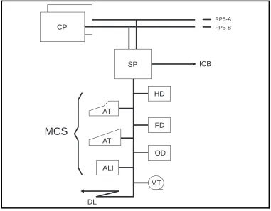
2.3.2 Man-machine Communication Subsystem (MCS)
General
MCS supplies the man-machine interface for operation and maintenance.
MCS handles two types of information:
•
alphanumeric information (commands, printouts)•
alarm information (internal, external).The subsystem consists mainly of software - mostly in the CP, but also in the SP - but some hardware does exist:
•
the alarm interface (ALI)MCS interworks with FMS (File Management Subsystem) which provides storage media for the Transaction Log and for some printouts.
MCS also interworks with SPS and DCS.
This interwork serves three main purposes:
•
communication between SP and CP for transfer of commands/printouts (SPS)•
communication with the terminals (DCS)•
operation and maintenance of the terminals (DCS).In the above communication the command path is:
SP CP
MCS...SPS...SPS...MCS
The terminal interfaces belong to DCS as will be seen in the section on this subsystem.
MCS interworks with all command receiving and printout generating blocks. It also interworks with all program blocks that generate alarms.
The Hardware of MCS
The hardware of MCS consists of the ALI and alarm panels.
The ALI and AT have already been described in chapter 2.2.3 IO Device Functions and Characteristics. Both the ALI and alarm panel hardware will be described in chapter 2.4 Hardware Structure.
The ATs - although handled by MCS - do not themselves belong to MCS (nor any subsystem).
Figure 2.8
ALI and the IO devices handled by MCS
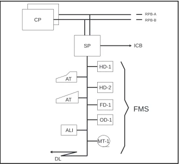
2.3.3 File Management Subsystem (FMS)
General
FMS incorporates hardware and software for handling the external mass storage of AXE.
The software of FMS is loaded both in the CP and the SP.
The hardware consists of mass storage Winchester hard disks comple-mented with the file devices for diskette drives, magnetic tape drives and optical disk drives, see figure 2.9.
DL
MCS
AT
AT
ALI
MT HD
OD
ICB
RPB-A RPB-B
CP
SP
Figure 2.9
The hardware of FMS
FMS interworks with SPS, MCS, DCS and a number of file users in other different subsystems.
The Hardware of FMS
The hardware of FMS consists of one Mass Storage Magazine (MSM) per node in IOG 11B. In IOG 11C the single MSM serves both Node A and Node B.
In IOG 11B5/C5 the FMS hardware includes also the Optical Disk Maga-zine (ODM), which contains the Optical Disk drive OD-1.
The MSM contains two Hard Disk drives, HD-1 and HD-2, and one Floppy Disk drive FD-1 in IOG 11B/B5. In IOG 11C/C5 there is one HD and one FD per node.
In IOG 11B/B5 two extra Hard Disk drives, HD-3 and HD-4, can be added to each node (only if 300 Mb hard disks).
The hardware also consists of at least one Magnetic Tape Group (MTG 10) in IOG 11.
The buses connecting the FMS hardware to the SP (SCSI buses) can also be included.
DL
FMS
AT
AT
ALI
MT-1 HD-1
HD-2
OD-1
ICB
RPB-A RPB-B
CP
SP
The hardware variants will be covered in chapter 2.4 Hardware Structure.
2.3.4 Data Communication Subsystem (DCS)
General
DCS supplies data communication support for operation and maintenance applications in AXE 10. DCS is transparent to all data entering or leaving the IOG via the terminals and data links.
The structure of DCS is based on the OSI model, i.e. a layered structure for data communication that is in general use today.
It is not necessary to know the principles of the OSI model for normal operation of IOG 11 and they will not be discussed further here.
DCS resides entirely in the SP, unlike the other three subsystems which exist in both the CP and SP.
Data from ATs or data links enters the system via DCS functions and is then transferred to either MCS or FMS within the SP. At start up of IOG 11, DCS accesses SPS directly.
DCS interworks with SPS, FMS and MCS.
This interwork serves three main purposes:
•
basic software maintenance of DCS (SPS)•
storage of DCS dependent data (FMS)•
operation and maintenance procedures (MCS)DCS offers communication services and provides interfaces to data net-work users.
It provides network services comparable to a stand-alone X.25 packet
switching system, which allows connection to external X.25 equipment
and X.25 networks.
An SP in IOG 11 operates from the DCS point of view as a switch or
Communication Module (CM) in a packet switched data network.
A CM is a logical concept. It defines logically the presence of DCS in the node (i.e SP). Within an IOG 11 each CM is numbered internally: in SPG-0, Node A is associated with CM-1, Node B with CM-2. It should be noted that in SPG-1, Node A is associated with CM-17, Node B with CM-18 etc.
The Hardware of DCS
The hardware is realized in the boards of a Line Unit (LU), the only hard-ware function block in DCS. The LUs contain the interfaces to the alpha-numeric terminals and data links.
2.4 Hardware Structure
2.4.1 Introduction
This chapter will explain the differences between the products that exist today in the IOG 11 family, i.e.:
•
IOG 11B-S•
IOG 11B-L2•
IOG 11B5-S•
IOG 11B5-L2•
IOG 11C•
IOG 11C5IOG 11A and IOMC will not be explained in detail since they are no longer supplied.
2.4.2 Different SP-Based IO Systems
IOG 11A
IOG 11A was the first release of the new generation of IO, based on APN 167. It was originally named IOG 11 (without “A”).
IOG 11B/B5
IOG 11B/B5 is a more powerful version of IOG 11A with respect to processor and disk capacity. These two products can be used with most types of APZ.
IOG 11B/B5 exists in two configurations. The standard configuration, IOG 11B/B5-S, is used for system back up, command handling, printouts, file handling, data link output, CPT commands etc. This is used for SPG-0.
IOG 11B/B5-L2 is a subset of the standard version with the functionality limited to support charging output or corresponding applications. There are no terminals or alarm functions connected to this configuration. It is used together with IOG 11B/B5-S. It has the same hardware as the stan-dard configuration except for the alarm interface boards. It is used for SPG-1, SPG-2 and SPG-3.
IOG 11C/C5
IOMC
IOMC was a single node compact version with products from IOG 11B and IOG 11C. It was intended to be used with APZ 211 10 for small sized applications. IOMC consists of one magazine.
All IO equipment is mounted in BYB 202 cabinets.
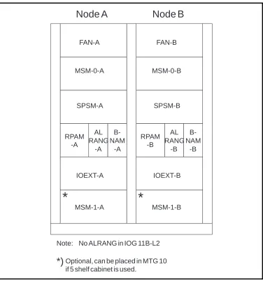
Figure 2.10
IOG 11B cabinet configuration
The IOG 11B cabinet contains the following magazines except for the air cooling (FAN) on top of the magazine:
•
MSM Mass Storage Magazine (FD and HD)•
SPSM Support Processor Subsystem Magazine (APN 167)•
RPAM RP bus Adapter Magazine•
ALRANG ALarm RANGing (external alarms)•
BNAM Bus Network Adapter Magazine (ICB)•
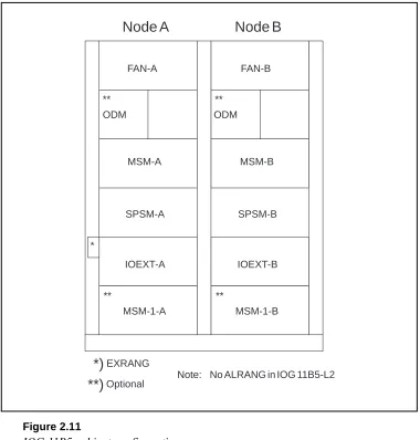
IOEXT Input Output EXTension (connection of AT, DL and containing the ALI).Figure 2.11 shows the cabinet configuration for IOG 11B5.
Node A
Node B
Note: No ALRANG in IOG 11B-L2
*)
Optional, can be placed in MTG 10if 5 shelf cabinet is used.
FAN-A FAN-B
MSM-0-A MSM-0-B
SPSM-A SPSM-B
RPAM -A
RPAM -B
IOEXT-A IOEXT-B
MSM-1-A MSM-1-B
*
*
AL RANG
-A B-NAM
-A
AL RANG
-B B-NAM
Figure 2.11
IOG 11B5 cabinet configuration
The IOG 11B5 cabinet contains the following magazines:
•
ODM Optical Disk Magazine (OD)•
MSM Mass Storage Magazine (HD and FD)•
SPSM Support Processor Subsystem Magazine (APN 167)•
IOEXT Input Output EXTension (connection of AT, DL and containing the ALI)•
EXRANG EXternal RANGing (external alarms).2.4.3 Magnetic Tape Group (MTG 10)
Magnetic Tape units are placed in separate cabinets.
Each SP is capable of handling one MTG 10. Each MTG 10 can consist of four Magnetic Tape Drives (MTD) but only one is necessary. For security reasons Ericsson recommend connection of two MTG 10s to an IOG 11, one to each node.
Node A Node B
Note: No ALRANG in IOG 11B5-L2
*)EXRANG
FAN-A FAN-B
ODM ODM
MSM-A MSM-B
IOEXT-A IOEXT-B
MSM-1-A MSM-1-B
SPSM-A SPSM-B
** **
** **
*
Optional
Figure 2.12 MTG 10
The MTG 10 cabinet contains (see figure 2.12):
•
A fan unit•
The Magnetic Tape Drive (MTD)•
The Magnetic Tape Magazine (MTM) with a power unit and one inter-face board per MTD, TDA-SC, for connection to the IOG 11 (see figure 2.13).Figure 2.13
The Magnetic Tape Magazine in MTG 10
CDR DRR DRR
DRR
FAN
MTD-0
MTM
FAN FAN FAN
Optional
MTD-1 MTD-2 MTD-3
(Master) (Slave)
(MT-1) (MT-2)
MTM
P O U
2.4.4 IOG 11B
IOG 11B consists of two nodes, one in each cabinet. It contains the follo-wing magazines:
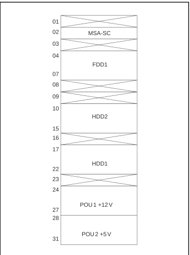
Mass Storage Magazine (MSM)
MSM (see figure 2.14) consists of two hard disk units, one flexible disk unit, a single interface for all units in the magazine and two power boards. The capacity of one hard disk is 300 Mb formatted.
MSA-SC Mass Storage Adapter SCSI (SCSI = Small Computer System Interface)
FDD Flexible Disk Drive
HDD Hard Disk Drive
POU Power Unit
A Mass Storage Magazine with two extra hard disks (no flexible disk drive) can be added to the system. This magazine is placed at the bottom of the cabinet. So, the possible configuration of hard disks in each node is one, two or four.
Figure 2.14
The Mass Storage Magazine in IOG11B
MSA-SC
FDD1
HDD1 HDD2
POU 1 +12 V
POU 2 +5 V 01
02
03
04
07
08
09
10
15
16
17
22
23
24
27 28
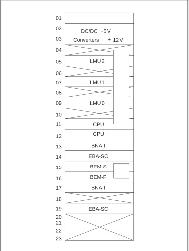
Support Processor Subsystem Magazine (SPSM-2)
The Support Processor Magazine used with IOG 11B is called SPSM-2.
The board positions in the SPSM-2 are shown in figure 2.15.
LMU Local Memory Unit
CPU Central Processor Unit (CP-3)
BNA-I Bus Network Adapter Interface (pos. 13 for RPA, pos. 17 for ICB)
EBA-SC Extension Bus Adapter SCSI (pos. 14 for FD/HD, pos. 19 for MT)
BEM-P/S Bus Extension Master Primary/Secondary.
The CPU, BNA, EBA-SC and BEM-P/S boards are interconnected in the backplane by the APN-bus (see also figure 2.20).
The memory boards (LMU) in the primary store have a capacity of 4 Mbytes each which gives the total primary store a capacity of 12 Mb.
The CPU consists of a double board. The processor in IOG 11B (CP-3) provides 80% more processing power compared to IOG 11A.
.
Figure 2.15
The Support Processor Subsystem Magazine in IOG 11B (SPSM-2)
DC/DC +5 V
Converters
LMU 2
LMU 1
LMU 0
CPU
BNA-I
EBA-SC
BEM-S
BEM-P
EBA-SC BNA-I 01
02
03
04
05
06
07
08
09
10
11
12
13
14
15
16
17
18
19
20 21 22 23
12 V -+
RP-bus Adapter Magazine (RPAM)
RPAM (see figure 2.16) contains the RPA which is the interface towards the RP-bus and helps handle the communication between the CP and the SP.
RPBU-A RP-Bus Unit A
RPBU-B RP-Bus Unit B
RIB Register In Buffer
ROB Register Out Buffer
TRU Transfer Register Buffer
DBH Data Buffer Handler
BUF Buffer
PRO Processor
Figure 2.16
The RP-bus Adapter Magazine in IOG 11B
DC/DC Conv. +5 V
RPBU-A
RIB
TRU
PRO
RPBU-B
DBH
ROB
BUF
01
02
03
04
05
06
07
08
09
10
Alarm Ranging (ALRANG)
ALRANG is a magazine without any boards, only a backplane- i.e it has no logic circuits. It is an interconnection unit for connecting external alarm sensors. Cables from the alarm sensors and from boards in the ALI in the IOEXT magazine are plugged in and connected together here. It is used since there is not enough physical space for 32 connectors on the ALI boards. ALRANG is normally needed in one side only (Node A).
Bus Network Adapter Magazine (BNAM)
BNAM is the interface towards the bus between the two nodes, the Inter Computer Bus (ICB). The BNAM is connected by a bus to the SP. The ICB is connected to the board in position 4 in BNAM (see figure 2.17).
BNALBus Network Adapter Line processor
Figure 2.17
The Bus Network Adapter Magazine in IOG 11B
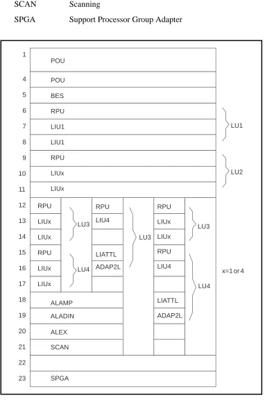
Input Output EXTension magazine (IOEXT)
The IOEXT magazine contains an interface board (BES) towards the SPSM in each node, i.e. it is the other end of the cross connection
mentioned earlier. It also contains the boards used for connection of termi-nals and data links. These are contained in Line Units (LU). In SPG-0, the IOEXT magazine also contains boards for alarm functions in the ALI.
The IOEXT magazine can contain a maximum of four LUs depending on the configuration. A LU consists of a Regional Processor Unit (RPU) and either one or two Line Interface Unit (LIU) boards. Figure 2.18 shows different possible configurations for the magazine.
BES Bus Extension Slave
RPU Regional Processor Unit
LIU1 Line Interface Unit (up to 19.2 kbit/s)
LIU4 Line Interface Unit (up to 64 kbit/s)
LIA-TTL Line Interface Adapter
01
02
03
04
05
DC/DC Conv. +5 V
ADAP2L Line Interface Adapter
ALAMP Alarm Panel
ALADIN Additional Alarm Panel
ALEX Additional Alarm External
SCAN Scanning
SPGA Support Processor Group Adapter
Figure 2.18
The IOEXT-2 showing alternative Line Unit Configuration
POU POU BES RPU LIU1 LIU1 RPU LIUx LIUx RPU LIUx LIUx RPU LIUx LIUx ALAMP ALADIN ALEX SCAN SPGA RPU LIU4 LIATTL ADAP2L RPU LIUx LIUx RPU LIU4 LIATTL ADAP2L LU3 LU4 LU3 LU3 LU4 LU1 LU2
The interface board BES is used for the cross connection between the IOEXT and SPSM magazines in both nodes, see figure 2.19.
Figure 2.19
The cross connection
The RPU contains software for the interface and protocols provided by the LU. The LIU is the board at which the terminal or data link is physically connected.
Two types of LIU board exist, LIU1 and LIU4.
Four asynchronous terminals or low speed data links (maximum 19.2 kbit/ s) can be connected to each of the two LIU1 boards.
Two high speed data links (maximum 64 kbit/s) can be connected to each of the two LIU4 boards.
P S P S
SPSM-A BEM (CM 1) SPSM-B BEM (CM 2)
The LIA-TTL and the ADAP2L boards are used to adapt the interface pro-vided by the LIU4 board for PCM (Pulse Code Modulation) data links. LIA-TTL is used for adaptation to the TTL-level and ADAP2L is used for adaptation between the V24 interface and PCM. These boards are only required for high speed data links using PCM as the transport media.
With the PCM interface only one LIU4 board can be used and only one data link can be connected. The data link is physically connected to the ADAP2L board.
On LIU1 there are four positions for the ports at which terminals and/or data links are connected. (Positions A*1 to A*4).
The ports are numbered 1, 2, 3 & 4 on the first LIU1 board and 9, 10, 11 & 12 on the second board.
The type of connection can be a terminal or a data link for this board, but if mixed the connections must be made in pairs, i.e. two data links then two terminals or vice versa.
On LIU4 there are two positions for ports (positions A*1 and A*3).
The ports are numbered 1 & 2 on the first LIU4 board and 3 & 4 on the second board.
As figure 1.18 shows, the IOEXT magazine can be equipped in different ways.
The RPUs are always located at positions 6, 9, 12 and 15.
IOEXT-2 is the standard IOEXT magazine of IOG 11B/B5-S.
In this configuration the magazine can be equipped with four LUs contai-ning either one or two LIU1 boards. It also contains the ALI.
IOEXT-3 is an optional configuration in IOG 11B/B5-L2. Standard configuration as IOEXT-2, but with LIU4 in board position 7. It can con-tain maximum three LUs each concon-taining one LIU4 board and the two adapter boards LIA-TTL and ADAP2L (positions 15&16, 18&19, 21&22) for PCM data links, but can be reconfigured for other types of high speed links.
The ALAMP board handles the alarm panel interface and the connection of sensors for eight external alarms. ALAMP is connected as a terminal to an LIU board.
For additional alarm panels, the board ALADIN is used.
Additional external alarms sensors are connected to the board ALEX via ALRANG.
The information connected by SCAN is sent to an Operation and Mainte-nance Centre via a data link connected directly to the board. The informa-tion can also be monitored in the exchange by a display containing LEDs called ACU, connected between the SCAN board and the modem.
Sixty-six channels are available on the data link: four alarm classes multi-plied by sixteen alarm categories plus one channel for system alarm status and one for attendance information.
Each of the boards ALAMP, ALADIN, ALEX and SCAN is connected by a bus.
SPGA supplies the alarm panels with power via the alarm interface, ALI.
Figure 2.20
IOG 11B hardware block diagram
RP A MTG 1 0 DRR MTG 1 0 CDR TDA-SC MSM-1 MSM-0 (Optional) SPSM RP AM BNAM BEM PCD-D ALD Node A IOEXT MDF MTG 1 0 DRR MTG 1 0 CDR MSM-1 MSM-0 (Optional) SPSM RP AM BNAM Node B IOEXT MDF MDF ICB ICB A B RPB ALRANG 1 C A T EGOR Y 4 (3) 4 (3) CA TEGORIES 1 3 1 3 LMU CPU EBA-SC BNA-I EBA-SC BNA-I BES BNA-L MODEM LIU 1 LIU 4 RPU MSA-SC
LIA-TTL ADAP2L LIU
2.4.5 IOG 11B5
IOG 11B5 consists of two nodes, one in each cabinet. It contains the following magazines.
Mass Storage Magazine (MSM)
When 300 Mb hard disks are used (see figure 2.14) for MSM layout and when 1,05 Gb hard disks are used (see figure 2.32).
Optical Disk Magazine (ODM)
The ODM (see figure 2.21) contains the Optical Disk (OD) unit (2x297 Mb), one Bus Interface Connection (BIC) board and two power units.
Each ODM is connected to the SP (EBA-SC) via an SCSI bus connected to BIC board.
Figure 2.21
The OD Magazine in IOG 11
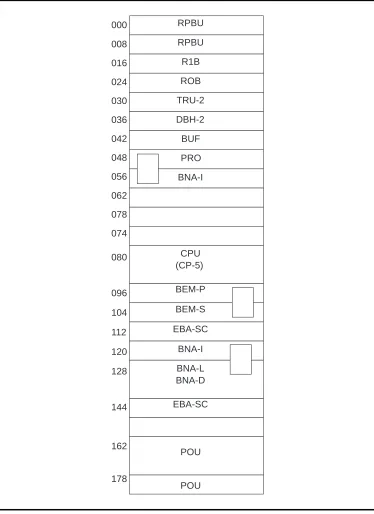
Support Processor Subsystem Magazine (SPSM-6)
The Support Processor Magazine used with IOG 11B5 is called SPSM-6. The board positions in the SPSM-6 are shown in figure 2.22.
RPBU RP-Bus Unit
RIB Register In Buffer
ROB Register Out Buffer
TRU Transfer Register Buffer
DBH Data Buffer Handler
BUF BUFfer
PRO PROcessor
BNA-I Bus Network Adapter Interface
CPU5 Central Processor Unit Type 5
BEM-P/S Bus Extension Master Primary/Secondary
EBA-SC Extension Bus Adapter SCSI
BNA-L/D Bus Network Adapter Line/Data processor
OD
B
I
C
P
O
U
Figure 2.22
The SPSM-6 Magazine
As it can be seen from figure 2.22 the SPSM contains the RPA (RPBU, RIB, ROB, DBH-2, TRU-2, PRO, BUF and BNA-I), APN 167 processor CP-5, interface towards HD, OD and MT (EBA-SC), towards IOEXT (BEM) and towards SPSM-B (BNA-I and BNA-LD).
The primary memory is 32 Mb and is located on the CPU (CP-5) board.
The processing capacity in IOG 11B5 (CP-5), is increased by more than 100% compared to IOG 11B (CP-3).
Input Output EXTension magazine (IOEXT) The same as in IOG 11B, see figure 2.18.
2.4.6 EXternal RANGing (EXRANG)
EXRANG is an interconnection unit for external alarms and is placed in the vertical cable runway opposite the IOEXT magazine. It replaces ALRANG in IOG 11B.
Figure 2.23
IOG 11B5 hardware block design (1.05 Gb HDs)
RPBU RIB ROB RPBU DBH-2 TRU-2
BUF BEM CP5
EBA -SC EBA -SC PRO BNA -I BNA -I BNA -L,D A B RPB BES RPU RPU RPU ALEX SCAN AL ADIN
Ext. al.
FAN-A,B AD AP2 LIA -TTL AL AMP LIU 4 LIU 4 LIU 1 AIL PC PR INV INV DU DU PCD -D PCM-MUX GS SPSM-A IOEXT -A BIC OD ODM-B BIC OD ODM-A MSM-B MSM-A
MTG 10 CDR
MTG 10 DRR
TD A -SC MT MT EXRANG MSA -SC FD HD BIC MSA -SC FD HD BIC BEM CP5 EBA -SC EBA -SC BNA -L,D BNA -I SPSM-B RPBU RIB ROB RPBU DBH-2 TRU-2 BUF PRO BNA -I RPB A B RP AM-A PC PR INV INV DU DU
LIU 4 LIU 1 LIU 1
RPU RPU
BES
PR
INV
MODEM MODEM
MOD or MDF MOD or MDF
2.4.7 IOG 11C
IOG 11C consists of one cabinet, see figure 2.24.
MSM Mass Storage Magazine
SPSM Support Processor Subsystem Magazine
IOEXT Input Output Extension
EXRANG External Alarm Ranging
Figure 2.24
IOG 11C cabinet configuration
Mass Storage Magazine (MSM2)
The Mass Storage Magazine in IOG 11C (see figure 2.25) is called MSM-2. It has space for one hard disk with 300 Mb or 1.05 Gb capacity and one flexible disk drive per node. It also contains one interface board for both HD and FD.
FAN
SPSM-A
SPSM-B
IOEXT
-A -B
MSM
-A -B
*
Figure 2.25
The Mass Storage Magazine in IOG 11C (MSM-2)
MSA-SC Mass Storage Adapter SCSI
HDD Hard Disk Drive
FDD Flexible Disk Drive
POU Power Unit
Support Processor Subsystem Magazine (SPSM-5)
The Support Processor Subsystem Magazine in IOG 11C (see figure 2.26) is called SPSM-5. It contains the RP-bus adapter, the APN 167 processor and interface boards towards other magazines.
The primary memory boards (LMU) have a capacity of 4 Mb per board which gives a total primary memory of 12 Mb.
Figure 2.26
The Support Processor Subsystem Magazine in IOG 11C (SPSM-5)
M S A -S C HD FD P O U P O U P O U P O U FD HD M S A -S C
Node A Node B
RPBU RP-Bus Unit
RIB Register In buffer
ROB Register Out Buffer
TRU-2 Transfer Register Buffer-2
DBH-2 Data Buffer Handler-2
BUF Buffer
PRO Processor
BNA-I Bus Network Adapter Interface (first BNA-I board is for RPA, second is for ICB)
LMU Local Memory Unit
CPU3 Central Processor Unit Type 3
BEM-P Bus Extension Master Primary
BEM-S Bus Extension Master Slave
EBA-SC Extension Bus Adapter SCSI
BNA-L Bus Network Adapter Line interface processor (ICB)
Input Output Extension (IOEXT-4)
Figure 2.27 IOEXT-4 configuration POU POU BES RPU LIU1 LIU1 RPU LIUx RPU LIUx LIUx ALAMP ALEX BES RPU LIU1 LIU1 RPU LIUx RPU LIUx POU POU RPU LIU4 LIATTL ADAP2L RPU LIU4 LIATTL ADAP2L LU2 LU3 LU2 LU1 ALI LU1 LU2 LU3 LU2 A-node
x=1 or 4
BES Bus Extension Slave
RPU Regional Processor Unit
LIU Line Interface Unit
LIATTL Line Interface Adapter
ADAP2L Line Interface Adapter
ALAMP Alarm Panel
ALEX Additional Alarm External
For the function of these boards see IOEXT magazine for IOG 11B.
External Alarm Ranging (EXRANG)
EXRANG is an interconnection unit for external alarms with the same function as ALRANG in IOG 11B. It is placed in the cable chute.
Figure 2.28
IOG 11C hardware block diagram
2.4.8 IOG 11C5
IOG 11C5 consists of one cabinet, see figure 2.29.
Figure 2.29
IOG 11C5 cabinet configuration
ODM Optical Disk Magazine (for description see figure 2.21)
MSM Mass Storage Magazine (for description see figure 2.32)
SPSM Support Processor Subsystem magazine (for description see figure 2.22)
IOEXT Input Output EXTension magazine (for description see figure 2.27)
EXRANG EXternal RANGing (for description see chapter 2.4.6 External Ranging)
Figure 2.30 shows a more detailed picture of IOG 11C5 hardware.
*)
EXRANG FAN-AODM
MSM
SPSM-B
IOEXT SPSM-A **
*
**)
Optional-A -B
Figure 2.30
IOG 11C5 hardware block diagram
RPBU RIB ROB RPBU DBH-2 TRU-2 BUF RPBU RIB ROB RPBU DBH-2 TRU-2 BUF BEM CP5 EBA -SC EBA -SC BEM CP5 EBA -SC EBA -SC PRO BNA -I PRO BNA -I BNA -I BNA -L,D BNA -L,D BNA -I A B RPB A B RPB BES RPU RPU AD AP2 LIA -TTL AL AMP ALEX
LIU 4 LIU 1 LIU 4 LIU 1 LIU 1
RPU RPU
BES
PC PR
INV
Ext. al. FA
N ALD AIL PC PR INV PR INV INV MODEM MODEM
MOD or MD
F
MOD or MD
F DU DU PCD -D PCM-MUX GS SPSM-A SPSM-B IOEXT -A BIC OD ODM MSM-B MSM-A MSA -SC FD MSA -SC FD HD HD
MTG 10 CDR
MTG 10 DRR
2.4.9 LEDs and Buttons
In the IOG hardware there are a number of lamps (LEDs) indicating diffe-rent states and faults that can occur in an IOG, see figure 2.31.
In the CPU (CP-5) board there are two leds, two toggle switches and two push buttons. For explanations see figure 2.31.
In the CPU (CP-3) board in IOG 11B and C there are two LEDs, see figure 2.31. The meaning of these LEDs is as follows:
GREEN YELLOW
OFF OFF CPU not responding
OFF ON After power on or reset. The status is set by the hardware. CPU and memory tests are started. Memory test = 1-5 minutes.
OFF FLASHING If self-test fails
ON ON Restart/Reload in progress
ON OFF Tests have been completed with no errors. The Bootstrap program boots the system. The booted system has
started and the file-loaded modules are ready to run. This is the NORMAL indication status.
There are also two push buttons on the CPU (CP-3) board front. These buttons should only be used in special situations. The upper button is for debugging of SP programs. It must not be pushed during normal operation. The lower (reset button) is for restarting (press once) or reloading (press twice) of the SP.
A terminal can be connected straight in to the SP on the CPU board. This is referred to as a local terminal. From this terminal only SP commands can be sent.
A local terminal is, for instance, used at initial start of IOG 11.
Normally an IO switch is used through which one terminal is connected to both the CPU port and a normal IO port.
For CP-5 the terminal is connected at position 080A*4F in the SPS maga-zine, and for CP-3 at position 12B*4F.
2.4.10 1.05 GBytes Hard Disk
A new hard disk was introduced for IOG 11B/B5 and IOG 11C/C5. This hard disk media will in the near future replace the current 300 Mb hard disk.
The storage capacity of the new hard disk is 1.05 Gb formatted (unformat-ted 1.27 Gb).
A maximum of 16 volumes starting on one hard disk is allowed. However, the maximum allowable number of volumes in an SPG is 16.
Figure 2.32 shows the layout of the Mass Storage Magazine in IOG 11B/B5 with the new hard disk.
Since this hard disk is SCSI based, there is no need for an MSA-SC (Mass Storage Adapter SCSI) board as an interface between the hard disk and the corresponding hard disk drive. The MSA-SC board must still be included in the system as an interface to the FD.
The hard disk is backplane connected, i.e. no front cable connections, exist.
The BIC (Bus Interface Connection) board in MSM is front connected to the EBA-SC board in SPS Magazine and is also front connected to the MSA-SC in MS Magazine.
Figure 2.32
The Mass Storage Magazine in IOG 11B/B5
01 02 03 04
07 08 09 10
15 16 17
22 23 24
27 28
31 21
MSA-SC
FDD1
HDD1 HDD2
POU 1 +12 V
2.5 Chapter Summary
•
IOG 11 is a Support Processor (SP) based IO system, where the SP is the processor that controls the IO system. It exists in several variants and we have described IOG 11B/B5 and IOG 11C/C5 in this module.•
The main functions for the IOG 11 are to handle data, store data and handle alarms.•
For connection to the RP bus, the IOG 11 has an interface called theRegional Process Adapter (RPA). The RPA is also called a Link and is
designated a RP-number.
•
The SP is also called a Node. For security reasons the nodes and links are duplicated. Together, they form a Support Processor Group (SPG). One IOG 11 can consist of four SPGs.•
The storage media for IOG 11 are Hard Disk (HD), Floppy Disk (FD),Magnetic Tape (MT) and Optical Disk (OD).
•
For man-machine communication we connect Alphanumeric Terminals (AT) to the SP. The Alarm Interface (ALI), which is the interface for connection of external alarms and the alarm panel(s), is connected to the SP as an AT.•
Data Links (DL) can be used for connection of remote terminals and fortransmission of data, e.g. charging data.
•
The IOG 11 consists of four subsystems: Support Processor Subsystem (SPS), File Management Subsystem (FMS), Man-machineCommunica-tion Subsystem (MCS) and Data CommunicaCommunica-tion Subsystem (DCS).
3. Command and File Handling
3.1 Chapter Objectives
Figure 3.1
Chapter objectives
Chapter Objectives
After completing this chapter the participant will be able to:
• Explain the purpose of the Entry Commands used with IOG 11.
• Name the entry commands for the four subsystems.
• Explain the difference between accessing the SP in local mode and accessing in normal command mode.
• Give the reason for accessing the SP in local mode and know how to enter local mode in two ways.
• Describe the different statuses of the units Link, Node, Line Unit, Network Port/Physical Port and Alphanumeric Terminal.
• Explain the concepts Executive and Standby in relation to the nodes in a node pair and describe how the Inter Computer Bus sends data between the two nodes.
• With a printout of the file attributes of a file, explain the different parameters that are assigned a file.
• Explain the concept Duplicated Volume and relate the unique characteristic of all such volumes.
• Describe the contents of the volumes PROG_A/PROG_B, OMFZLIBORD and RELVOLUMSW.
• Be able to use create, delete, write to, read from and execute a file with the help of the relevant Operational Instruction.
• Explain the purpose of the File Process Utility function giving the type of files that are normally transferred by this function.
• Use FPU functions to transfer files from hard disk to magnetic tape or via data link with the help of the relevant Operational Instruc-tion.
• Dump charging data to hard disk using the relevant Operational Instruction.
3.2 IOG 11 Command Handling
When using IOG 11 to enter commands it is necessary to distinguish between those commands that are owned by function blocks that only exist in the CP and those commands which are owned by blocks in the SP. Or, putting it in a slightly simplified way, one must distinguish between CP
commands and SP commands.
All commands that are addressed to the CP - for both APT and APZ blocks - are given in the normal way in accordance with the rules of the
man-machine language. IOG 11 is transparent for these commands and for the answer printouts received. This is shown in figure 3.2.
Figure 3.2
Command path for CP commands
When a command is to be given to an SP - in any SPG connected to the CP - the CP must first be told that this is the case. To do this, one must give a special entry command which opens a dialogue between the operator ter-minal and the required SPG.
The entry command is also called a path building command i.e. it is used to set up a path from the CP to the required SPG for the following
command sequence. The dialogue is then carried out from the terminal side using subcommands, e.g.
This entry command builds a path from the CP to an SP in SPG-0.
Entry commands are analysed in the normal manner by the ANA blocks in the CP. User authority and terminal authority verification can be
provided by the ANA blocks for these commands.
Each entry command owns a given set of subcommands, so once an entry command has been given correctly any of these subcommands can be entered.
The subcommands pass from the SP to the CP where they are directed to the required SPG. The CP is transparent for these commands i.e. no checks are made on the subcommands in the CP. The checking is carried out in the SP.
AT SP CP
COMMAND
PRINTOUT
An exception to the above is the case of some subcommands belonging to FMS which are processed in the CP from where signals are then sent to FMS in the SP to execute the required work.
The printouts are sent back to the terminal on the same path, see figure 3.3.
An exception to the above (figure 3.3b) is the special case of certain large result printouts received from the SP in own SPG. These can be sent directly to the terminal from the SP without going via the CP in order to save CP capacity.
Figure 3.3
a) Entry command and printout, own SPG b) Subcommand and printout, own SPG c) Entry command and printout, other SPG d) Subcommand and printout, other SPG
3.2.1 Entry Commands
For each subsystem there is more than one entry command. This is to enable the system to accommodate users who have different authority levels with regard to entry of commands.
AT CP
PRINTOUT SUBCOMMAND
d)
SP SPG-0
SP SPG-1
AT ENTRY CP
PRINTOUT
AT CP
SUBCOMMAND
PRINTOUT COMMAND
a)
b)
AT ENTRY CP
PRINTOUT COMMAND
c)
SP SPG-0
SP SPG-0
SP SPG-0
Three different entry commands exist for FMS, while DCS and MCS share the same three entry commands. SPS has just one entry command.
The commands used for DCS/MCS are general entry commands that would also be used for addressing functions belonging to Remote Meaure-ment Subsystem (RMS) and Statistics and Traffic MeasureMeaure-ment
Subsystem (STS) if these were loaded.
In each subsystem each command corresponds to a different authority level: high, middle and low.
High authority entry commands allow all subcommands for the subsystem to be entered.
Middle authority commands allow a limited number of subcommands to be entered.
Low authority commands allow only print subcommands to be entered.
The entry commands for each of the subsystems are listed below:
SPS (maintenance) FMS MCS/DCS/ SPS (operation)
IMMCT INMCT IMLCT INMIT IMLIT INMPT IMLPT
In the commands:
C is for Change and Printhigh authority I is for Change and Printmiddle authority P is for Printlow authority
When an entry command is given correctly, the system answers with a
colon, see below:
A subcommand can now be given after the colon.
A further entry command not previously mentioned is the command ISMCT.
This is a special entry command which is only used at start up of an IOG 11 - so called cold start.
On starting up the system, initial software is booted into the SP’s CPU from a diskette and this software allows commands to be entered from a terminal connected directly to a special port on the CPU board.
This terminal is called a local terminal. It is any asynchronous terminal set to 4800 baud. In IOG 11B5/C5 the terminal is connected at position
08-A-04 in the SPS magazine, in IOG 11B/C it is connected at position 12-B-04.
The command ISMCT is then used to allow the use of subcommands for formatting the hard disks, defining the hard disk volumes and loading the SP software to the hard disks.
The ISMCT command will only be accepted during the start up phase and therefore is not used for basic operation and maintenance.
Cold start of an IOG 11 is beyond the scope of this book and will not be covered further here.
3.2.2 Subcommands
A set of subcommands belongs to each of the entry commands. These are also found in the Command Descriptions in the B-Module.
When a subcommand is entered with the necessary parameters (if any) answer printouts are received in exactly the same way as with CP commands. After each of these printouts a new colon is given so that a new subcommand can be entered, and so on.
To end the dialogue the subcommand END must be given.
After this subcommand the communication returns to the CP and the ready mark is obtained. Normal CP commands can now be given. A new entry command must be given if a new session between the CP and an SPG is to be initiated.
An example of an entry command and subcommands is given in figure 3.4.
Figure 3.4
When the procedure printout ORDERED is received in answer to a subcommand, the dialogue must first be terminated before the terminal can be released. The subcommand END must be used.
After receiving EXECUTED the terminal can be released and the result printout obtained, see figure 3.5.
Figure 3.5
Use of END after printout ORDERED
As the dialogue has been terminated, if one wishes to continue with subcommands belonging to the original entry command then the entry command must be given again before it is possible to continue.
The above procedure can be speeded up by use of the character @. By giving this, one interrupts an ongoing dialogue and one leaves the entry command for temporarily.
This can be done at any time, for instance when it is necessary to give a command to the CP. To return to the entry command one must release the terminal.
On receiving ORDERED it is sufficient to type @ first and then release the terminal. As the terminal is released the result printout will be obtained if the job has already been carried out, followed by a return to the subcom-mand dialogue.
If the job has not been executed then the result printout will be obtained next time the terminal is released.
3.2.3 Local Mode and CPT Commands
As has been seen so far, all commands concerned with an SP - both entry and subcommands - are sent to the CP from the SP. The subcommands are directed by the CP back to the SP or to an SP in another SPG. However, the possibility exists to send commands to the SP which do not go on to the CP, but are handled directly by the SP.
To be able to do this, two conditions must be satisfied:
•
the commands must be SP commands, i.e. must belong to user blocks in the own SP•
the SP must be accessed by an operator working in local mode.Using local mode the operator talks directly to the SP and receives print-outs directly from the SP. This is illustrated in figure 3.6.
Figure 3.6
Command and printout paths in local mode
One can access the SP in local mode at any time, even if the CP is running, but obviously there is no reason to do this. The number of commands that can be addressed to the SP alone is limited.
The main use of local mode is to be able to access the SP when the CP is unavailable for some reason.
Should the CP become seriously faulty and IO commands are not accepted, then access to the system using local mode must be used to initiate a recovery process.
Within the SP software exists the function block CPT (Central Processor
Test system). This software - a number of Maintenance Subsystem
modules - allows us to access CPT hardware in the CP in order to facilitate testing and loading of the CP from hard disk.
To do this we must use a set of CPT commands. To be able to give CPT commands the SP must be accessed in local mode.
To use local mode a command is used: MCLOC. Access in local mode can be made from any terminal having authority for this command.
At loss of contact with the CP for any reason the message CP Unavailable, Enter EXIT or MCLOC is given.
AT CP
PRINTOUTS COMMAND
The command MCLOC will always be accepted provided that the SP is running. The sequence is given below:
USR and PSW correspond to the operator’s user name and password defined in the User Directory.
A master user and password are defined in the initial data but can be removed by the administration.
Commands can now be given to the support processor in the own SPG. It should be noted that MCS and DCS subcommands require no entry command when one is in local mode.
The entry command for these subsystems (IMLCT) is a general entry command and is not required in local mode. It can be given, however, without causing any problem.
The subsystem FMS has its own specific entry command and with this subsystem the entry command must be given when FMS is to be accessed in local mode.
The subsystem SPS is not accessable from local mode.
Local mode can also be attained by making use of the local terminal mentioned above. If, for instance, all Line Units are blocked then no access can be made to the system via the IOEXT magazines.
A terminal connected to the CPU board in the SP could be used to give SP commands to deblock the LUs.
When entering local mode using a local terminal then the command MCLOC is not required.
All four subsystems can be accessed in this case. the entry commands for SPS and FMS can be given without the SPG parameter.
The AT must be working with capital letters in this case. If contact is lost during a command sequence, the terminal must be switched to TTY (tele-type) mode and semicolon entered. On reception of the ready mark return to buffer mode.
An important difference to notice between normal mode and local mode of access is that when a terminal has to be released in local mode then the command EXIT must be used. To return to local mode the command MCLOC must be used again.
<MCLOC:USR=usr,PSW=psw; EXECUTED
3.3 Status of IOG 11 Units
The path from the CP to an Alphanumeric Terminal can be expressed as follows:
CP - RPA - SP - LU - NP/PP - AT CP Central Processor
RPA RP bus Adapter
SP Support Processor
LU Line Unit
NP Network Port
PP Physical Port
AT Alphanumeric terminal
These units can all have different working states as will be seen in this section.
3.3.1 RPA State
The possible states of an RPA or Link are:
•
Normal (NORM)•
Separated (SEP)•
Blocked (ABL, MBL,TBL = Test Blocked)A separated link is used to communicate with a separated CP-SB, e.g. during initial loading of the CP or for changes in the CP software (func-tional change).
A link can be separated by command if the CP is running, or by depressing the button on the PRO board of the RPA if the CP is not running.
A link can be blocked by command - this will be covered later in chapter 3.3.6 Blocking and Deblocking. It will then have the state manually blocked (MBL).
An SP-Link Fault will lead to the link being automatically blocked (ABL).
Figure 3.7 SP Link Data
3.3.2 Node Configuration Status
The term node has already been used when talking about an SP: i.e. Node A and Node B being the two SPs in an SPG.
The word node is just another word for SP. The node concept is fundamen-tal to the operation and maintenance of an SPG.
The two nodes in an SPG form a node pair. One of the nodes is designa-ted Executive (EX) and the other Standby (SB).
The EX/SB configuration with regard to nodes is implemented mainly for supervision of the nodes in an SPG.
Unlike the case with the CPs, the SPs do not carry out exactly the same job. In this case the EX node is involved in all the ongoing work in the IOG. Data dumped from the CP to hard disk (e.g. TT output) passes via the EX node and all alphanumeric communication goes to/from the CP via the EX node.
The SB node is used only to store data - received from the EX node via the ICB - in the duplicated volumes on hard disk.
The SB node normally only executes programs belonging to FMS as well as programs in SPS for its own supervision and for checking heartbeat sig-nals sent from the EX node and the CP.
When the SB node is fully operational it is basically idling, ready and waiting to take over in case of failure in the EX node.
Contrary to the case of the CP, there is no normal state with node A as EX and node B as SB. Either node can be