Analysis and Performance of Automobile
Engine Components Considering Thermal and
Structural Effects
Tanu Singhai
1, Abhishek Mishra
2, Rajiv Saxena
3, Sanjay Chhalotre
4P.G. Student , Department of Mechanical Engineering , LaxmiNarain College of Technology , Bhopal , India1
P.G. Student , Department of Mechanical Engineering , Oriental Institute Of Science & Technology , Bhopal , India 2
Assistant Professor , Department of Mechanical Engineering, LaxmiNarain College of Technology, Bhopal , India3
Associate Professor , Department of Mechanical Engineering , Gyan Ganga Institute Of Tech & Mgmt , Bhopal, India4
Abstract: This paper presents an investigation report of effect of various parameters which affect the performance of an automobile engine. Almost all internal combustion engines have at least one connecting rod to transmit the thrust of the piston to the crankshaft, and as the result the reciprocating motion of the piston is translated into rotational motion
of the crankshaft. From the viewpoint of functionality, connecting rods must have the highest possible rigidity at the
lowest weight capable to withstand varying loads. It has been found that structural failure of various components results in engine missing and starts producing noise and vibration during racing, mileage gets affected and black or white
smoke arise also pickup gets reduced. In automobile industrydamaged or broken parts are generally too expensive to
replace or repair especially in case of engine. In this concern we presented detailed analysis of causes along with preventive maintenance suggestion schedule for better engine life.
Keywords: Thermal fatigue; Bearing failures; Engine failures; Crankshafts, Connecting Rod, Piston Assembly.
I. INTRODUCTION
Crankshaft and connecting rods are the main components of internal combustion engines which convert reciprocating
displacement of the piston to a rotary motion. A typical automotive crankshaft consist of main journals, connecting rod
journals (crank-pins), counter weight, oil hole and a thrust bearing journal. During the service life, combustion and inertia forces acting on the crankshaft cause two types of loading on the crankshaft structure; torsion load and bending load.
Engine pistons are one of the most complex components among all automotive components. The engine can be called the heart of a car and the piston may be considered the most important part of an engine. The pistons form the bottom half of the combustion chamber and transmits the force of combustion through the wrist pin and connecting rod to the crankshaft. Piston failures arise due to many reasons: mechanical stresses; thermal stresses; wear mechanisms; temperature degradation, oxidation mechanisms; etc. Fatigue is a source of piston damages. Although, traditionally, piston damages are attributed to wear and lubrication sources, fatigue is responsible for a larger number of piston damages. And some damages where the main cause is attributed to wear and/or lubrication mechanisms may have in the root cause origin a fatigue crack [3]
Fig.1. The distribution of component failures Fig.2. The distribution of causes of failure
Since most common component failure is that of engine so we focused on engine block assembly which carry piston, connecting rod and crankshaft subjected to high thermal stresses as well as cyclic stresses which depends some extent on drivers driving habits.
II. LITERATURE SURVEY
[5] P S Shenoy et.al. studied detailed load analysis under service loading conditions for a typical connecting rod, followed by quasi-dynamic finite element analysis (FEA) to capture stress variations over a cycle of operation. It was found that even though connecting rods are typically tested and analyzed under axial loading and stress state, bending stresses are significant and a multiaxial stress state exists at the critical regions of connecting rod.[6] A. R. Bhagat et.al. describes the stress distribution of the seizure on piston four stroke engine by using FEA and analyzed the thermal stress distribution of piston at the real engine condition during combustion process. As a result it was observed that stress distribution on the piston mainly depends on the deformation of piston. Therefore, in order to reduce the stress
concentration, the piston crown should have enough stiffness to reduce the deformation.[7] Prabhala et al undergone
“Design And Weight Optimization Of IC Engine” by Replacing the steel components with aluminium alloy components. By observing the analysis results of two assemblies it was concluded that using aluminium alloy for both connecting rod and piston is more beneficial than using steel for piston as automatically overall weight is reduced there fore the power required to run itself by automobile is reduced resulting in the increase in the mileage.
III.METHODOLOGY
One cannot correct the cause of premature failure until he first determines what causes the failure. To determine
the cause of the failures, the following method was used:
Appearance – an illustration and brief description of a component that has failed due to a specific cause.
Damaging Action – what actually damaged the component under the conditions which were present?
Possible Causes – a listing of those factors capable of creating the particular damaging action.
Corrective Action – the action that should be taken to correct the cause of failure.
The major cause producing thermal stresses in engine due to
insufficient engine cooling
IV.CRANKSHAFT FAILURE
A crankshaft is usually distorted due to extreme operating conditions, such as “over-speeding” and “lugging”. It may also be caused by improper handling prior to installation. A distorted crankshaft subjects the main bearings to excessive loads, with the greatest load being at the point of greatest distortion. The result is excessive bearing wear. Also, the oil clearance spaces between journals and bearings are reduced, making it possible for metal-to-metal contact to occur at the point of greatest distortion.
Oil clearance near the parting line is decreased to such an extent that metal-to-metal contact between bearing and journal takes place, resulting in areas of above-normal wear. Also, improper seating between the bearing back and the housing bore may be present which hinders proper heat transfer causing localized heating of the bearing surface and thus reducing fatigue endurance.
Alternating loading and flexing of the connecting rod can cause the bearing housing to become elongated. And because replacement bearing shells, when installed, tend to conform to the shape of the bearing housing, this can result in an out-of-round bearing surface.
Fig.3. Scratches on upper main bearing half in crank shaft Fig.4. Scratches on upper main bearing caps
V. BEARING FAILURE
Dust, dirt, abrasives and/or metallic particles present in the oil supply embed in the soft babbitt bearing lining, displacing metal and creating a high-spot. The high-spot may be large enough to make contact with the journal causing a rubbing action that can lead to the eventual breakdown and rupture of the bearing lining. Foreign particles may embed only partially and the protruding portion may come in contact with the journal and cause a grinding wheel action. Foreign particles between the bearing and its housing prevent the entire area of the bearing back from being in contact with the housing base. As a result, the transfer of heat away from the bearing surface is not uniform causing localized heating of the bearing surface which reduces the life of the bearing. Also, an uneven distribution of the load causes an abnormally high pressure area on the bearing surface, increasing localized wear on this material.
MAJOR CAUSES OF PREMATURE BEARING FAILURE
Dirt 45.4% Overloading 8.1%
Misassembly 12.8% Corrosion 3.7%
Misalignment 12.6% Improper Journal Finish 3.2%
VI. CONNECTING ROD FAILURE
The connecting rod is subjected to a complex state of loading. It undergoes high cyclic loads of the order of
108 to 109 cycles, which range from high compressive loads due to combustion, to high tensile loads due to inertia.
Therefore, durability of this component is of critical importance.
A bent or twisted connecting rod results in misalignment of the bore, causing the bearing to be chocked so the bearing edge makes metal-to metal contact with the journal. These metal-to-metal contact areas cause excessive wear on the bearing surface.Alternating loading and flexing of the connecting rod can cause the bearing housing to become elongated. And because replacement bearing shells, when installed, tend to conform to the shape of the bearing housing, this can result in an out-of-round bearing surface.
In general connecting rod treated as individual is failed subjected to hydrostatic pressure lock. No much connecting rod failure observation is found due to overheating piston assembly (seizing), fluctuating loads and failure of main crank shaft big end bearing.
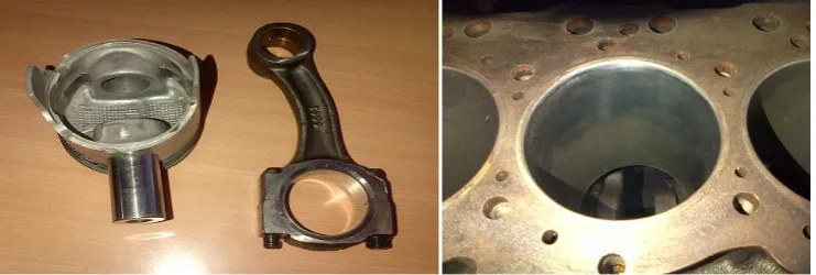
Whenever driver passes the car over the stored water on the ground and if there is chances of water coming inside in engine through exhaust pipe (silencer) then in that case hydrostatic locking of engine condition will observed. Figure 5 shows the hydrostatic lock effect on the connecting. Due to this only connecting rod is observed to be affected there is no any defect on piston is observed.
Fig.5. Hydrostatic Lock Effect Fig.6. Cylinder in good condition
Also it was observed that it does not affect cylinder as shown in Figure 6
For avoiding hydrostatic lock it is mandatory to pass over that kind of situation by putting vehicle in first gear, press 50% of accelerator paddle without fluctuation and slowly controlling through the clutch and cross the situation
VII.PISTON FAILURE
Fig.7. Worn out piston due to overheating
Consequent effects of piston can also be visualized on piston sleeves are shown in next Figure 8.
Fig.8. Worn out cylinder surface Fig.9. Worn out piston sleeves due to seizing of badly overheated piston
VIII.ENGINE COOLING AND LUBRICATION SYSTEM FAILURE
In the engine cylinders temperature of burning air fuel mixture may reach 2200°C or higher.It also affects cylinder walls and temperature of wall must not get hotter than 260°C.
The cooling systems are designed to keeps the engine at its most efficient temperature at all speeds and operating conditions. Higher temperatures cause lubricating oil to break down and lose its lubricating ability. To prevent overheating, the cooling system removes the excess heat.
Fig.10. Engine block assembly
IX.CONCLUSION
A survey of the types and causes of automotive component failures has shown that while failures resulting from abuse and such like are unavoidable, there is the possibility for a substantial reduction in automotive component failures. The following are seen as possible areas for attention from service point of view.
In condition of cold starting engine sudden acceleration must be avoided. Maintain proper ignition timing and valve timing. Timely change the engine oil, if vehicle not run up to specified km in that condition consider the time period which play very important role. Fixation of engine compartment with sufficient space especially backside of the engine for better heat dissipation space should be more.
ACKNOWLEDGEMENT
The author would like to thank the workshop of automobiles Ltd for allowing the publication of this Information.
REFERENCES
[1] A. M. Heyes, “Automotive Component Failures” Engineering Failure Analysis, Elsevier Science Ltd, Vol.5, No.2 pp.129-141, 1998. [2] F.S.Silva, “Analysis of a vehicle crankshaft failure” Engineering Failure Analysis, Vol.10, pp. 605–616, 2003.
[3] F.S.Silva, “Fatigue on engine pistons – A compendium of case studies” Engineering Failure Analysis,Vol.13 pp.480–492, 2006 [4] William H Crouse, Automotive Mechanics, Tenth Edition Tata McGraw Hill
[5] P.S Shenoy, A Fatemi “Dynamic Analysis Of Loads and Stresses in Connecting Rods” , J.Mechanical Engineering Science,Vol.220, pp.615-624 , 2006.
[6] A.R Bhagat ,YM Jibhate, “Thermal Analysis & Optimization Of IC Engine Piston using FEM” International Journal Of Modern Engineering Research, Vol.2, Issue.4, pp.2919-2921, 2010.