ABSTRACT
BORSE, JITENDRA ARUN. Real-time Image Based Rendering for Stereo Views of Vegetation. (Under the direction of Dr. David McAllister)
Real-Time Image Based Rendering for Stereo
Views of Vegetation
by
JITENDRA BORSE
A THESIS SUBMITTED IN PARTIAL FULFILLMENT OF THE REQUIREMENTS FOR THE DEGREE OF MASTER OF SCIENCE
COMPUTER SCIENCE
AT
NORTH CAROLINA STATE UNIVERSITY
RALEIGH, NC
2002
APPROVED BY:
Dr. David McAllister Chair of Advisory Committee
Dr. Christopher Healey
DEDICATION
To my Parents
To my Uncle
BIOGRAPHY
ACKNOWLEDGEMENT
I would like to thank Dr. David McAllister, my advisor, for his guidance, and motivation and for providing the opportunity to work with him. Dr. McAllister has been instrumental in bringing me to the field of computer graphics, and stereo and I am glad I got the chance to work with him.
I would like to thank Dr. Robert Rodman for being on my thesis committee and providing invaluable advice and support in so many ways over past two years. I would like to thank Dr. Christopher Healey for accepting to be a committee member and providing useful comments on this thesis from time to time.
I would like to thank my friends for being there when I needed them. Special thanks to Nihar, for his help in documenting this work.
Table of Contents
LIST OF FIGURES...VII
LIST OF TABLES... VIII
CHAPTER 1...1
INTRODUCTION...1
1.1MOTIVATION...1
1.2IMAGE BASED RENDERING...2
1.3SLICING...3
1.4OBJECTIVES...3
CHAPTER 2...5
PREVIOUS WORK...5
2.1TEXTURE MAPPING AND BILLBOARDING...5
2.2VIEW INTERPOLATION...6
2.3PRE-COMPUTED Z-BUFFER VIEWS...6
2.4QUICKTIME VR ...7
2.5LAYERED DEPTH IMAGES...8
2.6LAYERED IMPOSTORS...10
2.8SLICING...11
CHAPTER 3...12
BILLBOARDING...12
3.1INTRODUCTION...12
3.2LIMITATIONS...15
3.3BILLBOARDED FORESTS...17
CHAPTER 4...19
THE JAUKLIN ALGORITHM...19
4.1SLICING...19
4.1.1 Sparse and Solid Entities ...20
4.1.2 Generation of slices ...21
4.1.3 Blending...22
4.2ANOMALIES...24
CHAPTER 5...26
THE MODIFIED ALGORITHM...26
CHAPTER6 IMPLEMENTATION AND RESULTS...31
6.1PRE-PROCESSING:CREATION OF SLICES...31
6.2IMPLEMENTATION...31
6.3SYSTEM SPECIFICATIONS...32
CHAPTER 7 DISCUSSION...34
7.1SUMMARY...34
7.2FUTURE WORK...35
REFERENCES...36
APPENDIX A...37
List of Figures
Figure 1 Original Tree Model ... 4
Figure 2 An unconstrained camera path and an approximate path along the grid lines .... 8
Figure 3 Layered Depth Images... 9
Figure 4 Layered Impostors... 10
Figure 5 Generation of Billboard ... 12
Figure 6 Rotation of the billboard as viewer moves around the object (tree) ... 13
Figure 7 Billboard with transparency... 15
Figure 8 Forest using billboarding... 17
Figure 9 Sparse entities and solid entities... 20
Figure 10 Generation of slices... 21
Figure 11 Calculation of discrepancy angle... 22
Figure 12 Order of rendering the slices (top View) ... 23
Figure 13 Alpha Blending of slices ... 24
Figure 14 Nearly perpendicular slices. ... 27
Figure 15 Depth Reversal... 27
Figure 16 Split each slice into two ... 28
Figure 17 Order of rendering ... 29
Figure 18 Vegetation using the modified algorithm ... 30
Figure 19 Discontinuities caused by the algorithm... 30
Figure 20 Appendix A ( Billboarding )... 37
Figure 21 Appendix A ( Billboarding )... 38
Figure 22 Appendix A ( Billboarding )... 38
Figure 23 Appendix B ( Slicing ) ... 39
Figure 24 Appendix B ( Slicing )... 40
List of Tables
Chapter 1
Introduction
1.1 Motivation
Traditional computer graphics use 3D models to suggest a scene. Over the years, considerable efforts have been made to generate models that look realistic. These efforts have been successful, but at the expense of generating more complex models most of which have polygons as small as a pixel. Such models are computationally expensive with no upper bound on per frame computation requiring specialized rendering hardware. However, most applications demand real-time frame rates, in particular virtual reality environments.
1.2 Image Based Rendering
Given these complexities, we look at alternatives to using 3D models directly. An obvious solution to this problem is drawing as few polygons as possible. Our objective was to develop a system that would display high quality images at a constant and interactive rate, independent of scene complexity. Image-based rendering (or representation, IBR) has recently gained popularity and is currently a topic of active research. IBR has come up as an efficient way of generating novel views of an object /scene. IBR methods improve performance by rendering 2D objects in a way that makes them appear to be 3D. In fact, sometimes it’s possible to replace an entire 3D scene with a single polygon.
The main advantage of using image-based rendering methods over 3D models is that it is computationally less expensive, and rendering time is usually constant and not dependent on object complexity. With traditional rendering techniques, the time required to render an image increases with geometric complexity of the object. IBR replaces the three dimensional scenes with a set of images and rendering the scene is therefore independent of the scene complexity. IBR thus decouples scene complexity from rendering complexity by doing work proportional to the number of pixels in the final image instead of work proportional to the number of polygons in 3D model. Thus, higher frame rates can be attained. It should be noted that a constant and reliable frame rate is highly desirable in a real-time application.
that were occluded in the sampled images but visible in some intermediate view produce holes in the final image, which is not acceptable. The algorithm developed needs to eliminate all these drawbacks and specify an efficient method to obtain images.
1.3 Slicing
This work attempts to explore how the slicing technique proposed by Jauklin1 can be modified to generate stereoscopic images in real-time and how
to eliminate or reduce the effect of certain visual artifacts which are not very evident in monocular viewing but become obvious in stereoscopic views. The original (and modified) algorithm takes advantage of the lack of human ability to capture and remember minor details of a complex, moving object like tree. The viewer views the tree as a whole object rather than focusing on minor details like individual leaves. Vegetation also has holes through which objects behind it can be seen. All these complexities enable using simple manipulation and approximation to the original model.
1.4 Objectives
have similar height constraints, but cannot be used for applications where an aerial view of the vegetation is required.
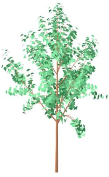
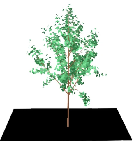
Stereo images are presented in the appendix for cross viewing2. Left and right eye images have been produced using off axis perspective projection. The model used as an example for this paper is shown in Fig.1. The performance statistics are based on a Pentium IV 1.7GHz processor and a NVIDIA Quadro2 MXR/XE graphics card.
Chapter 2
Previous Work
2.1 Texture Mapping and Billboarding
Texture mapping is the simplest form of image-based rendering. An image is mapped onto a surface in the scene. Billboarding3, a technique that
uses texture mapping simply maps texture onto a polygon, which orients itself according to changing view direction. The polygon is called a billboard. The billboard rotates around an axis and aligns itself to face the viewer as much as possible. In fact, billboarding of vegetation is a popular technique in representing trees in real-time applications and is very effective when the object is very far from the viewer. It is extensively used in a number of games. Simple texture mapping is further extended to map textures onto surfaces using environment maps or bump maps among others. These techniques improve the appearance of image textures and the surface.
2.2 View Interpolation
Chen and Williams4 carried the texturing concept further by using interpolated images to portray three-dimensional scenes. Their method exploits the fact that a sequence of images from closely spaced viewpoints would be highly coherent. Each image stores a set of camera parameters and a depth buffer. Using each pixel’s screen coordinates (x, y and z) and the camera’s relative location, a correspondence between the pixels in each pair of images is established by a 4x4 transformation matrix. The transformations are reduced to 3D spatial offset vectors for each of the pixels. The offset vector indicates the amount each of the pixels moves in its screen space as a result of the camera’s movement. The offset vectors are pre-computed and stored in a morph map, which represents forward mapping from one image to another. Using these maps, smooth interpolation between views is used to obtain the image from the current viewing position. These maps are better suited for smooth textured surfaces but not apt for objects like vegetation, which has high depth complexity.
2.3 Pre-computed Z-buffer views
Max and Ohsaki5 modified this approach and used z-buffer views
post process. However, this pixel-by-pixel reconstruction technique is too slow to be acceptable for real-time applications.
2.4 QuickTime VR
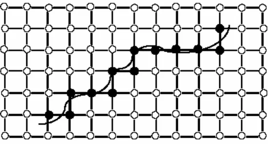
Chen6 presented an image-based system for creating and interacting with a virtual environment. The system uses environment map, in particular panoramic images, to compose a scene. The environment maps are orientation-independent images, which allow the user to look around in arbitrary view directions. Multiple environment maps are linked together to define a scene. Cylindrical images offer advantages because capturing a cylindrical panorama is easier than other types of environment maps. The system digitally warps one of these cylindrical images to obtain a new view. A 360-degree cylindrical image can be created by computer rendering, specialized panoramic cameras, or by stitching together overlapping photographs taken with a regular camera.
Figure 2 An unconstrained camera path and an approximate path along the grid lines
All the processing is done on-the-fly using a software-based real-time image-processing engine. This image-based approach was implemented in the commercial product, Quicktime VR, built on top of Apple Computer's Quicktime digital multimedia framework. If only the view direction is changing and the viewpoint is stationary, this method offers a very efficient solution. However, moving freely in the scene is difficult, requiring large number of environment maps, and defining smooth interpolation between a set of environment maps. This technique serves the purpose very well if used for backdrops providing immersive quality, but not very useful to represent a single object.
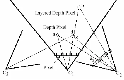
2.5 Layered Depth Images
handle more disocclusions and improve parallax. Each pixel in an image is represented by multiple depth pixels. Instead of storing a 2D array of depth pixels, a 2D array of layered depth pixels is stored. A layered depth pixel stores a set of depth pixels along one line of sight sorted in back to front order. The front element in the layered depth pixel samples the first surface seen along that line of sight.
Figure 3 Layered Depth Images
The method uses a incremental warping algorithm to create an output image from a new camera position. It defines a camera matrix composed of an affine transformation, a projection matrix, and a viewport matrix for each camera position. Given a new desired camera position, a transfer matrix, T1,2=C2C1-1 is generated where C1 is the LDI camera’s matrix and C2 is the
output camera’s matrix. Given image co-ordinates of a point (e.g., a in Figure 5) seen in LDI camera the transfer matrix computes image co-ordinates as seen in the output camera (e.g., a2 in Figure 5). However, the results as stated provide
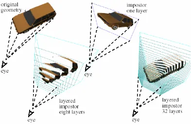
2.6 Layered Impostors
Figure 4 Layered Impostors
Another method uses layered impostors8, but it focuses more on
2.8 Slicing
Chapter 3
Billboarding
3.1 Introduction
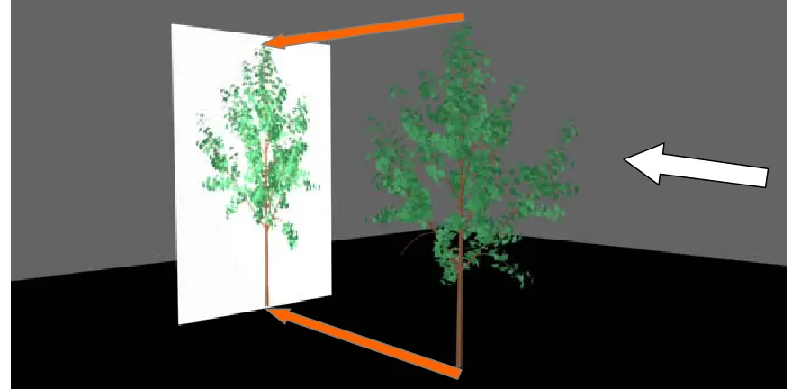
A billboard is a flat surface (panel, fence, wall, etc) on which signs or advertisements are posted. In a 3D graphics context, it would be just a logical extension to the above concept. A billboard in this context is defined as a polygon onto which a texture is mapped and the technique of doing this is known as billboarding. It is one of the most elementary of IBR methods. The texture is normally an image of a complex object, and the polygon is a rectangle whose orientation is changed as the viewer moves around the scene. The billboard rotates such that it faces some target, camera, another object or some point in the scene. Generally, it faces the camera or the viewer. However, certain applications might require the billboard facing a target other than the viewer. For example in games, a football player will always face the ball.
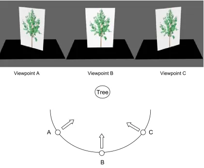
Fig.2 explains this concept of generating billboard and Fig.3 illustrates how to use it in the scene.
Viewpoint A Viewpoint B Viewpoint C
Tree
A C
B
Figure 6 Rotation of the billboard as viewer moves around the object (tree)
clouds. It can be used to achieve some goal related to the purpose of an application e.g., some application might require a particular object to always face a particular target, where the target can be the viewer or another object in the scene or a particular direction.
Billboarding can be adapted and implemented with several variations. Fig.2 illustrates the most basic billboarding method. A tree is billboarded into the scene. Trees are one of the most common objects billboarded in many applications, especially in games where trees are used more in the background rather than in the foreground. A single tree image is obtained and mapped onto a rectangle. The source of this image can be a 3D model or a photograph of real vegetation. As the viewer moves around in the scene, the billboard is rotated about a vertical axis through the trunk to face the viewer.
Billboarding is best suited for symmetrical objects. Objects like trees are said to be cylindrically symmetric for all practical purposes, with a vertical axis through the trunk of the tree being the axis of symmetry. Such objects allow rotation only about a vertical axis. They are rotated about such an axis to reorient the billboard as the viewer moves. Objects like clouds, bushes, and smoke have spherical symmetry. Such geometries allow billboards to be rotated up and down along with right and left i.e., the billboard can be rotated about any arbitrary axes as it has infinite axesof symmetry.
Figure 7 Billboard with transparency
Selective portions of the billboard can be made transparent. In Fig.4, portions of the billboard where vegetation is not present are transparent. The parts of the billboard image that one doesn’t want to display can be handled appropriately by making corresponding portions of the billboard transparent. How transparency is handled is an implementation issue. For images obtained by rendering 3D models, the model can be rendered with a white or a particular colored background (take care that this color is not present anywhere else in the vegetation) and drawing pixels can be drawn with this chosen color transparent e.g., if possible, RGBA images can be used with alpha values set to zero for pixels not belonging to vegetation.
3.2 Limitations
3.3 Billboarded Forests
Figure 8 Forest using billboarding
Chapter 4
The Jauklin Algorithm
4.1 Slicing
Billboarding enables real-time rendering of complex entities; however, the quality of images offered by billboarding is not acceptable in an environment where high scene realism is desired. Aleks Jauklin introduced an image-based multi-layered representation of vegetation, which provided significant improvement in quality over billboarding, offering high quality realistic images of vegetation. This method, known as slicing, uses a set of pre-rendered images to represent vegetation from a viewpoint. Such images are generated from multiple viewpoints, which are selectively blended to obtain a view of the vegetation from any random viewpoint approximately at the same elevation above the ground.
4.1.1 Sparse and Solid Entities
The Jauklin algorithm combines traditional mesh-based and comparatively new image-based rendering approaches. Vegetation is separated into solid entities and the sparse entities, which structurally form two different units. Trunk and limbs form a solid entity and the crown comprising the sparse entities of leaves and twigs.
Figure 9 Sparse entities and solid entities
from the same viewpoint. When used in a scene, slices are drawn in back to front order without the need of Z-buffer.
4.1.2 Generation of slices
Fig. 7(a) Fig. 7(b)
Figure 10 Generation of slices
The Jauklin algorithm renders the trunk and the crown separately. The trunk is rendered using mesh-based simplification. This rendering takes place while the application is being executed. The crown is pre-rendered to generate slices, which are used by the application as textures. The color and lighting for this online rendering of trunk and the offline rendering of the crown must be matched to hide the difference in environment. Aleks Jaulkin suggests computing textures by pre-computing the vertex lighting in a radiostiy package for the whole tree. This pre-computed vertex lighting data must then be used to render textures in the application.
The tree is pre-rendered from six different viewpoints around the tree at the same height from the ground. All six points are equally spaced angularly at the same horizontal distance from the tree. Each slice in every slicing has the same dimensions, and the distance between adjacent slices is the same for every slicing. The orientation of slicing is fixed and independent of the observer's position.
4.1.3 Blending
Two adjacent slicings are used to generate views of the vegetation from any arbitrary point. Note that this algorithm works well only for points that are approximately at the same relative height. Hence, further references to an arbitrary point would mean an arbitrary point at a particular height, unless mentioned. The algorithm determines the slicings closest and second closest to the viewpoint. The author defines the angle between slicing and the direction of viewing as the discrepancy angle. The slicing having the lowest discrepancy angle is known as primary slicing and the second lowest as secondary slicing. The levels of transparency for both the slicings are varied. The transparency of the slicings is proportional to the discrepancy angle. The transparency varies between zero and one.
Primary Slicing Viewpoint Secondary Slicing
5B - 5A - 4B - 4A - 3B - 3A - 2B - 2A - 1B - 1A
The primary and secondary slicings are blended using the calculated transparencies. Each slicing must be drawn in the correct back-to-front order. First, the farthest secondary slice is drawn, followed by farthest primary, second farthest secondary, second farthest primary, continuing so until all slices belonging to the two slicings are drawn. Fig.8. illustrates the ordering.
This practical method enables interactive rendering of vegetation. The results achieved with respect to number of trees and frame rate is acceptable for a real-time application like VR. The multi-layered images encapsulate the required depth information. This provides the necessary depth perception to give the viewer the feel of a 3D model.
Figure 13 Alpha Blending of slices
4.2 Anomalies
These artifacts can be attributed to the use of blending, however smooth, and to change in the order of slicings being drawn on the screen.
The slicings drawn are partially transparent with their transparency levels varying as viewer moves around the scene. The transparency varies between 0 and 1. As slicing is introduced into the scene, it starts with opacity of 0, gradually increasing to 1 and finally decreasing to 0 and disappearing. When emerging (alpha increasing), parts of the vegetation appear as if moving out of fog. Similarly, when a slicing fades out (alpha decreasing) those corresponding parts of the vegetation begin to disappear. This particular phenomenon is very distracting in stereo. In monocular viewing, due to a lack of depth perception, one does not notice the part of vegetation in front which is disappearing.
Appearance and disappearance are important issues, which need to be corrected before adapting this method in stereo. Besides this, there is a change in order in which the primary and secondary slicings are drawn. As the viewer continues to move around the tree, at a certain point, the discrepancy angle becomes equal for both the primary and the secondary slicing. At this point, the primary and secondary slicings are interchanged. There is a change in the order in which the slicings are drawn. This switch is easily noticeable, in stereo. When swapping occurs, leaf and branches that were in front in previous frames appear to be at the back and vice-versa.
Chapter 5
The modified Algorithm
In this chapter we present modifications to the 'slicing and blending' algorithm by Jauklin. The original algorithm produces visual artifacts. We modify the algorithm so that it displays all pre-rendered images simultaneously, and slicings are partitioned and rendered in a back-to-front order. This approach improves the quality of the stereo, maintains the basic appearance of the vegetation, and reduces visual artifacts; however, it increases rendering time slightly.
The modifications produce a rendering that is not totally faithful to the original vegetation model. Our goal is to produce acceptable stereo images of forests of vegetation in real-time and to produce views that appear "natural" in a walk-through environment. The images reproduced by our modified algorithm maintain the "treeness" property of vegetation, generating a close approximation of the original model.
Fig. 14 (a) Fig.14 (b)
Figure 14 Nearly perpendicular slices.
Another disturbing anomaly in stereo is depth reversal. The parts of vegetation supposed to be behind are drawn over those that are meant to be in the front. This happens because the primary and secondary slicings intersect each other. Depth relations are reversed. Certain parts of vegetation appear to move in one direction and the remaining in the opposite direction. This occurs in stereo because depth is conveyed and can be very distracting.
This phenomenon can be understood with the help of top view shown in Fig.11. Consider segments 1, 2, 3 and 4 to be drawn. Let 1 and 2 belong to line A and 3 and 4 belong to line B. If we draw A first followed by B, we observe that 3 lying behind 1 is drawn over 1. If the order of lines were reversed, 2 gets drawn on top of 4.
To correct this, the modified algorithm splits each slice vertically into two halves. Considering the pre-processing step, each plane is cut into two halves. Fig.12. illustrates this. We now refer to each half plane a slice. The left halves form one slicing and the right halves from another. From 3 viewpoints, distributed on a circle, 60 degrees apart and at same distance above ground, 6 such slicings are obtained. The center of this circle lies on a vertical axis V, through the centroid of the object (which is same for each slicing in our case). Other constraints remain the same as the original algorithm i.e., each slice has the same dimensions, and the same distance exists between adjacent slices. The coordinates in the scene to which each slice is to be mapped are pre-determined.
Fig. 16(a) Fig. 16(b)
The slicings are then displayed in back to front order. In addition, every slice of each slicing is drawn in back to front order relative to the viewpoint.
As shown in fig.13 below, we number slices from 1 to 6 in counterclockwise direction. To generate the view from point A, the order would be 2-1-3-6-4-5, and from point C it would be 6-5-1-4-2-3. Also, note, when drawing slicing 3 viewed from point C the order of slices would be e-d-c-b-a and from point A it would be a-b-c-d-e.
Figure 17 Order of rendering
Figure 18 Vegetation using the modified algorithm
Another inherent defect in the Jauklin Algorithm is discontinuities in geometry created by the slicing. Different parts of a single branch may be projected on different planes of the same slicing. Fig.15. illustrates this. A branch with this property has been highlighted. Fortunately, this aberration usually goes unnoticed due to the dense nature and random complexity of vegetation. However, if this appears to be a problem, these parts of vegetation can be obscured by foliage.
Chapter 6
Implementation and Results
6.1 Pre-processing: Creation of slices
The 3-d model required to generate the slices was obtained from www.3dcafe.com. The model is a 3-D Max file of a tree. The model was rendered using the following parameter settings for illumination viz. ambient lighting and no directional light sources. The required clipping planes were then defined to represent the corresponding slices. Each slice was rendered and stored as an image file (256 x 256 or 512 x 512 pixels) image dimensions were restricted to powers of 2 for performance optimization. Every slice was then split over a vertical axis. The slices were created using an orthographic projection. The slices were taken by viewing the model from 3 view points 60 degrees apart. This gave us a total of 15 slices, each split into 2. If prior information regarding the position and orientation of the tree in the final scene is known, then it is possible to applying illumination specific to the tree before slicing it. However, for a generic case as in the example provided, the model had no special lighting.
6.2 Implementation
loaded every time it had to be rendered. A texture object stores the texture data and can be used whenever required. Due to the use of objects, the texture does not need to be loaded every time as the previously loaded data is used. Using such texture objects is the most efficient method for texturing. No blending was used to render the textures. The textures were loaded as RGBA pixels with each of the R, G and B values set to a value less than a threshold of 100. The alpha value is 1 giving the texture a 100 % transparency.
The same tree was also rendered using the Billboarding method mentioned in chapter 3.
6.3 System specifications
6.4 Results
The following tables depict the rendering times using our algorithm and billboarding.
Resolution : 512 x 512 Resolution : 256 x 256
Number of trees Approximate Frames per sec.
Number of trees Approximate Frames per sec.
1 38 1 63 2 22 2 38 3 19 3 25 4 14 4 22 6 11 6 15 8 8 8 12 10 6 10 11 15 4 15 7 20 3 25 6
Table 1 Frame rate using the modified algorithm
Billboarding
Number of trees Approximate Frames per sec.
20 25 30 24 40 19 50 13 60 11 70 10 80 9 100 8 125 6 200 5 225 4
Chapter 7
Discussion
7.1 Summary
In case of an environment where the viewer’s attention is generally focused on a single 3-D model, it becomes necessary to be able to produce views of the model that change continuously as the user moves around in the environment. Doing this gives it the required realism to produce an immersive walk-through. The slicing method which we use gives us such capabilities.
In cases where a large amount of vegetation is present in an immersive scene, the attention of the viewer is not just focused on specific areas of the vegetation, but on the overall vegetation. This implies that there is no real need to render vegetation in detail. So the transparency, motion parallax and the limited vegetation complexity present in the scene can still be realistically rendered using billboarding techniques. In scenes where there is dense vegetation, the viewer is less likely to notice that he is being presented with the same view of a given tree or different views of the same tree. So billboarding is efficient in such situations and allows one to attain better frame rates, thus reducing the chance of flicker.
7.2 Future work
For both billboarding and slicing, the stereo rendering problem is easily partitionable in a multiple processor environment in a straightforward way. Hence, one would expect acceptable frame rates in this case, even with large numbers of trees in the scene. This is an area for future research.
The implementation does not support lighting and shadows. This aspect as regards to image based rendering has not yet been explored to a sufficient level.
References
1. Jauklin, "Interactive Vegetation Rendering with Slicing and Blending," Eurographics 2000 short presentations.
2. D.F. McAllister (Editor), Stereo Computer Graphics and Other True 3D Technologies, p. 5,26, Princeton University Press, Princeton NJ, October 1993.
3. McReynolds, Tom, D. Blythe, B. Grantham and S. Nelson, “Programming with OpenGL: Advanced Techniques,” course 17 notes at SIGGRAPH’98, 1998.
4. S. E. Chen and L. Williams, "View interpolation for image synthesis," Proc. ACM SIGGRAPH 93, pp. 79-288, 1993.
5. N. Max and K. Ohsaki, "Rendering trees from pre-computed Z-buffer views," Eurographics Workshop on Rendering 1996, pp. 165-174, 1996.
6. S. E. Chen, “QuickTime VR – An Image-Based Approach to Virtual Environment Navigation”, SIGGRAPH 95, pp. 29 – 38, 1995.
7. J. Shade, S. Gortler, Li-wei He and R. Szeliski, "Layered Depth Images," SIGGRAPH ‘98, pp. 231-242, 1998.
8. G. Schaufler, "Per-Object Image Warping with Layered Impostors," Eurographics Rendering Workshop 1998, pp. 145-156.
Appendix A
Stereo Images for cross-eyed viewing using
Billboarding
Figures 20, 21 and 22 show a forest, from three pre-computed directions, at same height above ground and 30 degrees apart, rendered using the billboarding technique.
Figure 21
Appendix B
Stereo Images for cross-eyed viewing using
Slicing
Figures 23, 24 and 25 show a tree rendered from three pre-computed directions, at same height above ground and 30 degrees apart using the billboarding technique.
Figure 24