18th International Conference on Structural Mechanics in Reactor Technology (SMiRT 18) Beijing, China, August 7-12, 2005 SMiRT18-F04-2
RECENT DEVELOPMENTS FOR FAST REACTOR STRUCTURAL
DESIGN STANDARD (FDS)
ABSTRACT
For realization of reliable and economical fast reactor (FR) plants, Japan Nuclear Cycle Development
Institute(JNC) and Japan Atomic Power Company(JAPC) are cooperating on “Feasibility Study on Commercialized FR Cycle Systems”. To certify the design concepts through evaluation of their structural integrity, the research and development of “Elevated Temperature Structural Design Guide for Commercialized Fast Reactor (FDS)” is recognized as an essential theme. FDS focuses on particular failure modes of FRs such as ratchet deformation and creep fatigue damages due to cyclic thermal loads. To evaluate these modes, three main developments are in progress. One is “Refinement of Failure Criteria” for particular modes of FRs. Next is development of “Guidelines for Inelastic Design Analysis” in order to predict elastic plastic and creep behaviors. Furthermore, efforts are being made toward preparing “Guidelines for Thermal Load Modeling” for FR
component design where thermal loads are dominant. These studies were performed under the sponsorship of
the Ministry of Economy, Trade and Industry of Japanese government.
KEY WORDS: Fast Reactor, Structural Design Standard, Failure Criteria, Inelastic Analysis, Thermal Load
1. INTRODUCTION
The Japan Nuclear Cycle Development Institute (JNC) and Japan Atomic Power Company (JAPC) are cooperating to conduct a research and development program called the “Feasibility Study on FBR Cycle” (Feasibility Study) for analyzing the practical application of the fast breeder reactor (FBR) cycle [1]. This study aims at the development of a reactor system that implements the concept of a plant with superior safety and economy. For this purpose, such plant designs are tried as the compact and simple nuclear reactor structure, shortening of the piping, and the use of new structures such as the intermediate heat exchanger combined with the pump. To achieve drastic rationalization of above design, sophistication of the structural design standard was required. Therefore, the JNC and JAPC have been conducting research and development program for developing “Elevated Temperature Structural Design Guide for Commercialized Fast Reactor (FDS)” since 2000 on a contract basis with the Ministry of Economy, Trade and Industry. This report describes the recent progress of this joint research.
The first established fast reactor structural design code in Japan is the “Elevated Temperature Structural Design Guide for Class 1 Components of Prototype Fast Breeder Reactor (BDS) [2]” which was developed by extension of the ASME B&PV Code Sec. III CC1592[3]. Introducing additional developments of materials and structural analysis methods to BDS, the “Elevated Temperature Structural Design Guide for Demonstration Fast Breeder Reactor (DDS) [3]” was developed.
Furthermore, commercialized fast reactors have different design needs from prototype and demonstration fast breeder reactors. To satisfy above needs, new design methods are developed and integrated with DDS into
Hiroshi SHIBAMOTO, Hideaki NAGASHIMA and Kazuhiko INOUE
The Japan Atomic Power Company, Tokyo, Japan
[email protected], [email protected], [email protected]
Naoto KASAHARA, Kyotada NAKAMURA and Masaki MORISHITA
O-arai Engineering Center, Japan Nuclear Cycle Development Institute, Ibaraki, Japan
FDS with two sets of guidelines for inelastic design analysis and for thermal load modeling.
2. MAIN R&D ISSUES FOR STRUCTURAL DESIGN OF COMERCIALIZED FAST REACTOR
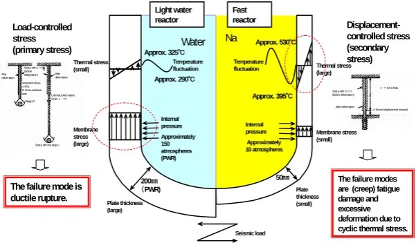
Particular characteristics of fast reactor structural design are low pressure and high temperature conditions due to the use of liquid metal as coolant. Under a high-temperature condition, the thermal stress induced by the temperature difference in the structure increases; further, the elastic plastic and creep deformation easily occur due to a decrease in the yield strength of the material. Additionally, under a low-pressure condition, the possibility of ductile fracture and creep failure is low. Consequently, ratchet deformation and creep-fatigue damage due to cyclic thermal stress become dominant failure modes in fast reactor components (Figure 1).
Light water reactor
Fast reactor
Water Na
Temperature fluctuation
Temperature fluctuation
Approx. 530℃
Approx. 395℃ Approx. 325℃
Approx. 290℃
Internal pressure Approximately 150 atmospheres (PWR)
Internal pressure
Approximately 10 atmospheres Thermal stress
(small)
Membrane stress (large)
Plate thickness (large)
Plate thickness (small)
Membrane stress (small) Thermal stress (large)
50㎜ 200㎜
(PWR)
Seismic load
Load-controlled stress (primary stress)
The failure mode is ductile rupture.
Displacement-controlled stress (secondary stress)
The failure modes are (creep) fatigue damage and excessive deformation due to cyclic thermal stress. Status with σ= 0
(before deformation) After deformation
After deformation Generated stress σ=P/S S: Cross-sectional area
Weight P Unlimited deformation: Strainε→∞
Status with too large σ
Status with Δl = 0 (before deformation)
After deformation ε =Δl/l is finite.
Δl (forced displacement amount)
Figure 1 Dominant failure modes in FR plants
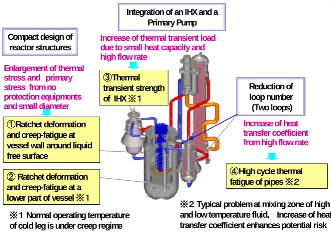
Design research is being conducted on a sodium-cooled commercialized reactor as feasibility study. A compact and simple plant design shown in Figure 2 is examined for improving its reliability and economy from prototype and the other available demonstration reactors. Abbreviation of protection equipments for the reactor vessel wall (reactor wall cooling system, etc.) increases the thermal stress on the relevant section. Further, in a small, thin-walled vessel, the primary stress for supporting the core weight overlaid on the reactor vessel wall becomes larger than that observed in previous fast reactors. These loading conditions enhance ratchet deformation and
(creep) fatigue damage at a vessel wall around liquid free surface (①) and at a lower part of vessel (②).
With regard to the cooling system, adoption of an integrated primary pump and intermediate heat exchanger reduces the heat capacity of coolant against power output whereas the flow velocity increases, resulting in a
severe thermal transient load (③). Reduction in the number of loops enhances heat transfer coefficient from high
flow rate. It increases risk of high cycle thermal fatigue of pipes which is typical problem at mixing zone of high
and low temperature fluid (④).
In order to overcome above structural design problems, FDS introduces several new technologies such as Figure 3. Some severe parts of reactor vessel and IHX locate in cold leg where normal operating temperature is under creep regime. To treat these parts as non-creep design area, classification method of high-temperature design area is improved (A). When both ratchet strain and fatigue damages increase, there is a possibility of those interaction. Failure criteria considering above interaction is investigated (B). To predict inelastic response of structures preciously, inelastic constitutive equations(C) and design evaluation method based on inelastic analysis results (D) are recommended. In spite of severer thermal loads, conventional design guides for FRs has no rule for thermal load modeling. Load modeling methods are studied for system thermal transient load (E) and thermal striping load (F).
Above developments are integrated with DDS into FDS which consists of “Elevated temperature structural design guide”, “Guidelines for Inelastic Design Analysis” and “Guidelines for Thermal Load Modeling”.
Integration of an IHX and a Primary Pump
Reduction of loop number
(Two loops)
Increase of thermal transient load due to small heat capacity and high flow rate
③Thermal transient strength of IHX ※1
Compact design of reactor structures
②Ratchet deformation and creep-fatigue at a lower part of vessel※1
④High cycle thermal fatigue of pipes ※2 ①Ratchet deformation
and creep-fatigue at vessel wall around liquid free surface
※2Typical problem at mixing zone of high and low temperature fluid, Increase of heat transfer coefficient enhances potential risk
Enlargement of thermal stress and primary stress from no protection equipments and small diameter
※1Normal operating temperature of cold leg is under creep regime
Increase of heat transfer coefficient from high flow rate
Figure 2 Structural design problems of commercialized fast reactor
(B) Consideration of ratchet strain - fatigue interaction (A) Classification of high-temperature design area
(F) Thermal striping load
(E) System thermal transient load Structural design problems
Re ac tor V ess el C ool ing c irc ui ts
(C) Constitutive equations
(D) Design evaluation method based on inelastic analysis results
Developed design evaluation methods
②③ ①② ②③ ④ ①② ①②
③Thermal transient strength of IHX ※1
②Ratchet deformation and creep-fatigue at a lower part of
vessel※1
④High cycle thermal fatigue of pipes ※2
①Ratchet deformation and creep-fatigue at vessel wall around liquid free surface
El ev at ed temp erature st ru ctural des ig n G ui de G uid el in es fo r ine las tic d es ign an al ys is G uid el in es fo r th erm al lo ad m od elin g
3. ELEVALTED TEMPERATURE STRUCTURAL DESIGN GUIDE
3.1 Classification of high-temperature design area
In the existing BDS[2] and DDS[4], the creep design area in a plant system is judged based on a comparison of the highest temperature during operation and a uniform limiting value (425°C for austenitic steel such as 316FR steel and 375°C for ferrite steel such as 12Cr steel) regardless of operating time. The influence of creep is frequently over-estimated in sections for which operation time at a high temperature is short. There are critical components that are normally used in a relatively low-temperature area and for which the
high-temperature hold time is short (※ in Figure 2). Therefore, it needs to develop rational classification
method for the high-temperature design area.
The French RCC-MR[5] code adopts a more rational method of judgment than the Japanese BDS and DDS by combining temperature and time. The actual creep strength depends on the temperature, time, and stress. In the current research, a rational method for judging the creep design area is examined based on the combination of temperature, time, and stress.
3 5 0 4 0 0 4 5 0 5 0 0 5 5 0 6 0 0 6 5 0
Tim e(h r)
T
em
p
er
a
tur
e(℃
)
Conventional Criteria for Ferrite Steel
Conventional Criteria for Austenite Stainless Steel
60year×92% operation
375℃ 465℃
425℃ 480℃
1,000 100
10 1
0.1。 10,000 100,000 1,000,000
316FR Steel
12Cr Steel
σ=1.5Sm,εc=0.0003mm/mm
Figure 4 Negligible Creep) curve
3.2 Consideration of ratchet strain - fatigue interaction
In FDS, a rational limit is assigned to ratchet strain. On the other hand, recent researches suggest that a ratchet strain of even 1% to 2% may influence fatigue life or creep-fatigue life. Consequently, it becomes necessary to understand the influence of the ratchet on creep-fatigue life in the operation conditions of fast reactors. So that, ratcheting-fatigue tests were conducted to examine the influence of ratchet on creep-fatigue strength.
Figure 5 shows the concept underlying the test. The x-axis indicates the number of cycles of strain, while the y-axis indicates the accumulated amount of strain. In the ratchet-fatigue test, cyclic strain at a constant amplitude and ratchet strain (accumulated strain) are overlaid. The following load patterns can be considered depending on the method of applying ratchet strain in the overall life. (I) Strain is given as pre-strain in the initial stage. Based on the existing knowledge, a decrease in lifetime due to the existence of mean strain is not found. (II) In the overall life, strain is increased gradually. Recent tests indicate a significant decrease in lifetime. (III) As an intermediate between the above two patterns, ratchet strain is gradually increased until the number of cycles reached No; subsequently, saturation occurs. For load pattern (III) described above, we obtained the result of a preliminary test using the number of cycles until saturation occurs as a parameter.
Test data obtained until now are shown in Figure 5. The x-axis of the figure indicates the ratio of the number
of cycles until saturation of ratchet strain occurs N0 to the lifetime at fatigue test Nf0. The y-axis indicates the
ratio of the lifetime at the ratcheting-fatigue test Nf to the lifetime at fatigue test Nf0. Values smaller than 1
along the y-axis indicate a decrease in fatigue strength due to the ratchet. In the test, we changed N0 and
examined the variation in strength due to the change. Other conditions such as material (316FR steel), temperature (550°C), strain range (0.5%), strain rate (0.1 %/s), and ratchet strain (1.41%) were held constant.
thermal transient number is less than several hundreds. On the other hand, fatigue strength decreases if ratchet strain is applied during the overall life.
Since above results, FDS limits accumulated inelastic strain within 2% considering ratchet strain - fatigue interaction.
Number of cycles Mixed test with parameter N0:
Lifetime ? Pre-strained test: Lifetime dose not decrease
Number of cycles reached to specific accumulated strain No
Incremental strain test: Lifetime decreases
Stra
in
c
ε
ε Δ
:Accumulated strain
0.0 0.5 1.0 1.5
0 5 10 15
Ac c u mu late d strain (% )
Fa
ti
g
ue
lif
e
r
a
ti
o
Δε=0.5%,低サイクル疲労試験 Δε=0.5%,N0=20
Δε=0.5%,N0=1000 N0=Nf
予ひずみ試験(N0=1)
Low cycle fatigue
2%
Low cycle fatigue with pre-strain
Average tr end Low
er trend
Figure 5 Summary of ratcheting-fatigue test conditions and results
4. GUIDELINES FOR INELASTIC DESIGN ANALYSIS
4.1 Basic policy and scope
Although the application of the inelastic analysis methodology to design has been tried since 1970[6] little progress has been made. One of the major reasons for this is lack of definitive constitutive equations for describing elastic-plastic-creep behavior of materials. Furthermore, the detailed constitutive equations that were developed for the purpose of realistic modeling of inelastic behavior of materials can accurately simulate test results, for which the material characteristics and load history are known. However, these conditions are uncertain in the design phase, which results in insufficient use of the advantage. That is another major reason.
The basic policy of developed guidelines is more rational evaluation result than that obtained by existing elastic analysis, and a conservative to design conditions, including essentially uncertain factors [7]. Since inelastic analysis has many influence factors on the results, it is difficult to secure maintenance of general conditions. Therefore, the scope of this set of guidelines is limited by considering the features of materials and load of fast reactors to avoid this problem.
The material used is assumed to be austenitic stainless steel (ex.316FR). Loading conditions are low primary stress ones such as design conditions in sodium systems of fast reactors that receives basically displacement-controlled load. Failure modes to be evaluated are assumed to be ratchet deformation and (creep) fatigue damage.
4.2 Constitutive equations
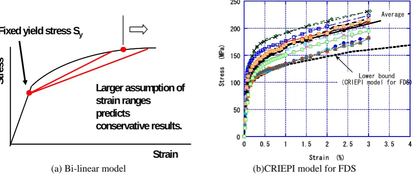
For fast reactor design by inelastic analysis, the two kinds of constitutive equations are recommended. One is “Bi-linear model” for easy treatment of inelastic calculation. Another is “CRIEPI model for FDS” to achieve precious estimation. Ratchet deformation and (creep) fatigue damage mainly depend on strain. Therefore, above constitutive equations are made use to predict larger (conservative) strain, since there are no constitutive equations that can evaluate both conservative stress and strain.
“Bi-linear model is one of the familiar constitutive equations. Therefore, it is easy to be used and often is provided as a standard option in many popular analysis codes such as ABAQUS, MARC and FINAS. This classic model can be simply described, which enables easy understanding. Main influence factors on strain of this model are work hardening, cyclic hardening and Bauschinger’s effect. All of these factors are modeled to predict larger strain. Bi-linear approximation of stress-strain curve is made as Figure 6 for conservative consideration of work hardening and cyclic hardening. When an assumed strain range is larger than an obtained result, it is a conservative solution. For conservative treatment of Bauschinger’s effect, a kinematic hardening model with restriction of yield surface moving is adopted.
simulate lower bound of both monotonic and cyclic stress-strain curves with 99% reliable range.
Fixed yield stress Sy
Larger assumption of strain ranges
predicts
conservative results.
Strain
Stress
0 50 100 150 200 250
0 0.5 1 1.5 2 2.5 3 3.5 4
Stres
s
(MP
a)
Strain (%)
Average
Lower bound (CRIEPI model for FDS)
0 50 100 150 200 250
0 0.5 1 1.5 2 2.5 3 3.5 4
Stres
s
(MP
a)
Strain (%)
Average
Lower bound (CRIEPI model for FDS)
(a) Bi-linear model (b)CRIEPI model for FDS
Figure 6 Recommended Constitutive Equations
4.3 Design evaluation method based on inelastic analysis results
(1) Modeling of the load history
Since inelastic analysis results depend on the load history which is undetermined in the design stage. Design load history should be modeled to bound capable loading conditions of actual plants.
The realistic load modeling procedure is proposed for conservative prediction as shown in Figure7. Conventional design codes based on elastic analysis, usually define unit load cycle composed of load events that can determine stress range for ratcheting and fatigue evaluation. The first step of load modeling procedure is extraction of unit load cycles, whose stress ranges exceed shakedown limit. Furthermore, kinds of unit loads are reduced by enveloping small unit loads with larger ones. The second step is to envelop all unit loads with the largest one. This assumption is appropriate for the Reactor vessel adjacent to coolant surface level, where the design-based event making stress over the shake-down limit is only “Plant start-up”, although various design-based events exist. That eliminates the difficulty of the load history effect. When above assumption becomes over conservative, more than two kinds of unit load cycles are necessary to be considered. Step3 is arrangement of order of different unit loads to predict larger strain by minimizing number of stabilized stress-strain cycles. Minimization of repeat numbers of the same unit load cycle, for example, can meet this requirement.
(2) Creep fatigue damage evaluation method
Creep fatigue damage is evaluated by both stress and strain, however there are no constitutive equations which provide both conservative stress and strain. Therefore, only strain is utilized from inelastic analysis results and stress is estimated indirectly from strain.
Fatigue damage is estimated by the equivalent strain range and the fatigue curves with Miner’s rule. The equivalent strain range is obtained from inelastic analysis results.
Step1: Extraction of unit load cycles whose stress ranges exceed shakedown limit
Reduction of kinds unit loads by enveloping small unit loads with larger ones
Step2: Envelope all unit loads with the largest one
Step3: Arrangement of order of different unit loads to predict larger strain by minimizing number of stabilized cycles
In the case of over conservative No history effect Define unit load cycle composed of load events that can determine stress range
Elastically calculated stress(☆)
→Conservative stress Si’(★)
Stress range -Strain range relationship Stress range -Strain range relationship
Δεt
Inelastically calculated strain range
Si’ S
p1
Sp2
Elastically calculated stress
σ
0 Sp2
Sp1
ε
σ
0 Sp2
Sp1
ε Initial stress Inelasticaly calculated
strain range
Creep damage by time fraction rule Dc Initial stress
Stress range -Strain range relationship
Elastic follow-up parameter
Stress relaxation history
From right diagram
Fatigue damage by
Miner’s rule Df
Creep-fatigue damage Df+Dc
Figure 7 Modeling of the load history Figure 8 Creep-Fatigue Evaluation Procedure
5. GUIDELINES FOR THERMAL LOAD MODELING
5.1 System thermal transient load
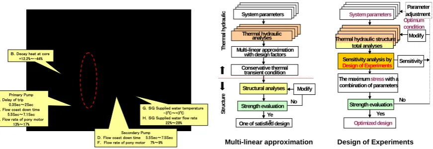
Thermal stress generated by the temperature variation of the coolant that is caused by the operation status of plants is called “system thermal transient load”. It is one of the principal loads for FR components. This load is affected by many kinds of parameters such as “system parameters”. Since each effective factors has a variable range as in figure 9, “system thermal transient load” should consider the most severe case among combinations of effective factors.
Conventional design procedures evaluate thermal-hydraulic and structural characteristics individually. For estimating the former, tendency of the coolant temperature change to the variation of the effective factors is obtained from parametric thermal-hydraulic analysis. In order to envelop the above tendency, coolant temperature histories are conservatively approximated by multi-linear curves with design factors. This thermal transient conditions are then passed to the structure design side, and geometries possible in this condition are identified from the structural analysis in this procedure (Multi-linear approximation in Figure 10).
B.Decay heat at core +12.2%~-44%
Primary Pump A.Delay of trip
0.3Sec~2Sec C.Flow coast down time
5.5Sec~7.1Sec E.Flow rate of pony motor
13%~17%
Secondary Pump D.Flow coast down time 5.5Sec~7.5Sec F. Flow rate of pony motor 7%~9%
G.SG Supplied water temperature -3℃~+3℃ H.SG Supplied water flow rate
22%~28%
Reactor Vessel
IHX
Steam Generator
Turbine
Optimized design
Sensitivity analysis by
The maximum stresswith a combination of parameters
Modify Parameter adjustment
Sensitivity
System parameters
Thermal hydraulic structure total analyses Thermal hydraulic structure
total analyses
Strength evaluation No Yes
Design of Experiments Multi-linear approximation
Structural analyses Modify
One of satisfied design Strength evaluation Conservative thermal
transient condition
Th
er
m
al h
yd
rau
lic
Ye s
No
熱流動解析 熱流動解析 熱流動解析
Thermal hydraulic analyses
Str
uc
tu
re
Design of Experiments
Optimum condition
System parameters
Multi-linear approximation with design factors
Figure 9 Effective factors on system thermal Figure 10 Evaluation Procedure for
transient load load modeling
5.2 Thermal striping load
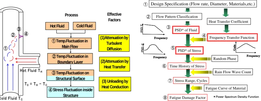
Recent investigation on thermal striping has revealed that amplitude of temperature fluctuation was attenuated during a series of fluids mixing to structural response by (1)turbulent diffusion, (2)heat transfer and (3)heat conduction as in figure 11 [11]. Above attenuations depend on frequency of temperature fluctuation. A wall model subjected to sinusoidal fluctuation of fluid temperature can explain this mechanism[12]. If a frequency of fluctuation is very low, whole temperature of the wall easily respond to fluid temperature, because thermal diffusivity homogenizes structural temperature. Therefore, low frequency fluctuations do not induce large thermal stress that is caused from temperature gradients in structures. On the other hand, a wall surface cannot respond to very high frequency fluctuation, since a structure has a finite time constant of thermal response due to heat capacity. Therefore, high frequency fluctuations do not lead to large thermal stress. As a result, there are special frequency area that are damageable.
“Thermal striping load” is evaluated by 4 step screening rules considering above attenuation factors. The first step is simple and conservative method without consideration of attenuation factors. The second step takes attenuation by only turbulent diffusion into account. The third one considers (1)turbulent diffusion, (2)heat transfer and (3)heat conduction, however conservatively bounds frequency characteristics. The forth one makes consideration of all attenuation factors with frequency characteristics. Among them, the first, second and the third steps are based on the same idea as the JSME guideline for light water reactors [11]. The forth one is explained here since it is new proposal.
In order to consider frequency effect, power spectrum density function (PSD) quantified frequency characteristics of fluid temperature and thermal stress fluctuations. Figure 12 illustrates the thermal stress evaluation procedure based on PSD. Required input data is ordinal design specifications such as flow rates,
diameters, material properties and wall thickness of pipes ①. According to momentum ratio between main and
branch pipes which is calculated from flow rates and diameters, flow patterns are classified into three patterns
such as wall jet, deflecting jet, and impingement jet [13] ②. For each pattern, design chart gives
Non-dimensional PSD of fluid ③. Frequency transfer function from fluid temperature to thermal stress can be
theoretically derived from heat transfer coefficient, material properties, wall thickness and constraint condition
[12] ④. This function transfers PSD of fluid to PSD of stress ⑤. By using inverse Fourier transformation, PSD
of stress is transformed into time history of stress. In this step, random phase is assumed in order to simplify the
mixing database in fluid ⑥. The rain flow wave counting method extracts stress ranges and cycles from time
Hot Fluid TH
Cold Fluid TC
(1)Attenuation by Turbulent Diffusion
(2)Attenuation by Heat Transfer
(3) Unloading by Heat Conduction
Hot Fluid Cold Fluid
①Temp.Fluctuation in
Main Flow
②Temp.Fluctuation in
Boundary Layer
④Stress Fluctuation inside
Structure
③Temp.Fluctuation on
Structural Surface
Effective Factors
① ②
③ ④
Process
T0 = TH - TC
Frequency
Gain
Frequency
Gain
Frequency
PS
D T
f
Frequency
PS
D T
f
Frequency
PS
D
σ
Frequency
PS
D
σ
*Power Spectrum Density Function
Flow Pattern Classification ①
②
③
④
⑤
⑥
⑦
⑧
Design Specification (Flow rate, Diameter, Materials,etc.)
Heat Transfer Coefficient
PSD* of Fluid
Frequency Transfer Function
PSD* of Stress
Random Phase
Time History of Stress
Rain Flow Wave Count
Fatigue Curve of Material Stress Range, Cycles
Fatigue Damage Factor
Figure 11 Thermal Fatigue Mechanism
Figure 12 Thermal Stress Evaluation
ProcedureInduced by Fluid Temperature Fluctuation
by Power Spectrum Density Function
6.CONCLUSIONS
Japan Nuclear Cycle Development Institute(JNC) and Japan Atomic Power Company(JAPC) are cooperating to develop “Elevated Temperature Structural Design Guide for Commercialized Fast Reactor (FDS)”. New design methods to satisfy design requirements of commercialized fast reactors are integrated with “Elevated Temperature Structural Design Guide for Demonstration Fast Breeder Reactor (DDS)” into FDS which consists of “Elevated temperature structural design guide”, “Guidelines for Inelastic Design Analysis” and “Guidelines for Thermal Load Modeling”.
“Elevated temperature structural design guide” is DDS plus (A) classification method of high-temperature design area and (B) failure criteria considering ratchet strain - fatigue interaction, with other improvements related with failure criteria. “Guidelines for Inelastic Design Analysis” recommends (C) constitutive equations and (D) design evaluation method based on inelastic analysis results. “Guidelines for Thermal Load Modeling” provides modeling methods for (E) system thermal transient load and (F) thermal striping load.
Adequacies of new developments were proved for particular design cases. To extend these appricable area, experimental validation are continued. Details and back ground of above guidelines will be presented by associated papers.
7. AKNOWLEDGEMENT
The present study reflects the results of the study titled “New Reactor Technology Verification Test for Power
Generation” that was conducted under contract with the Ministry of Economy, Trade and Industry We are deeply thankful to the Design Technique Sophistication Committee and its Chairman (Emeritus Professor Asada, University of Tokyo) for their valuable advise that directed the above research.
We also express our gratitude to Tomomi Otani of Mitsubishi Heavy Industries, Ltd., Daisuke Sadahiro of Fuji Electric Systems Co., Ltd., Uasunari Nakayama of Kawasaki Heavy Industries, Ltd., Masakazu Jinbo of Toshiba Corporation, and Masayuki Sukekawa of Hitachi, Ltd. for their immense cooperation in carrying out this research.
REFERENCES
[1] Y. Sagayama et al : “Overall Plan and Progress Situation of “The Feasibility Study on Commercialized FR Cycle Systems”, GLOBAL 2003, (2003)
[2] Iida, K. et al., 'Construction Codes for Prototype FBR MONJU', NED 98, pp283/288., (1987)
[3] ASME,'Background of the ASME Boiler and Presure Vessel Code for design of elevated temperature class1 components in Sec.III', New York,(1974)
[4] Kawasaki,N. et.al., Recent Design Improvements of Elevated Temperature Structural Design Guide for DFBR in Japan, SMiRT15, Div.F, F04/4,(1999)
Paris,(1985)
[6] Dhalla,A.K. et al.,’Simplified Methods, in Reccommennded Practice in Elevated Temperature Design: A Compendium of Breeder Reactor Experiences, Vol.II - Preliminaly Design and Simplified Methods’,WRC Bulletin 362, WRC, New York,(1991)
[7] Y.Tanaka et al : “Development of the guideline on inelastic analysis for design”, ASME,PVP2004, PVP-Vol.472, pp53/60,(2004)
[8] Y.Takahashi, N.Ohno, G.Yagawa, "Improvement of Structural Integrity Assessment Guideline for Fast Reactor Components Part I: Evaluation of Defects-
free Structures", SMiRT16, No.F1426,(2001).
[9] Naoto KASAHARA, Masakazu JINBO and Hiromi HOSOGAI, Mitigation Method of Thermal Transient Stressby Thermal hydraulic-Structure Total Analysis, SMiRT17, F03-1,(2003)
[10] William Y. Fowlkes and Clyde M. Creveling, Engineering Methods for Robust Product Design: Using Taguchi Methods in Technology and Product Development, Prentice Hall PTR, (1995)
[11] JSME, Guideline for Evaluation of High-Cycle Thermal Fatigue of a Pipe, S017 (2003)
[12] N.Kasahara and H.Takasho., Stress response functions to multi-dimensional spatial fluctuations of fluid temperature, ASME, PVP-Vol.443-1, pp25/31, (2002)