Article
1
Compact and Powerful: A Vacuum Powered Soft
2
Textile-Based Clutch
3
Ali Sadeghi1,*, Alessio Mondini 1 and Barbara Mazzolai 1,*
4
1 Center for MicroBioRobotics; Istituto Italiano di Tecnologia (IIT); Pontedera (Pisa), 56025; Italy
5
* Correspondence: [email protected]; [email protected]
6
7
Abstract: In this paper, we present the design, manufacturing and characterization of a soft
textile-8
based clutch (TBC) that switches between locking and unlocking of its linear displacement by
9
exploiting vacuum stimulation. The applied vacuum locks the relative sliding motion between two
10
elaborated textile webbings covered by an elastic silicone rubber bag. Based on different fabrication
11
techniques, such as silicone casting on textile, melt embossing for direct fabrication of miniature
12
patterns on textile and sewing, we developed three groups of TBC samples based on friction and
13
interlocking principles and we compared their performance in blocking configuration. The clutch
14
with interlocking mechanism presented the highest withstanding force (150 N) respect to the one
15
(54 N) recorded for the friction-based clutch. The simple and compact structure of the proposed
16
clutch, together with the intrinsic adaptability of fabric with other clothing and soft materials, make
17
it a proper solution for applications in soft wearable robotics and generally as locking and variable
18
stiffness solution for soft robotic applications.
19
20
Keywords: soft clutch; soft robotics; textile based clutch; wearable robotics; soft actuator, exosuit;
21
variable stiffness; stiffness control; textile
22
23
1. Introduction
24
Clutches are locking devices widely used in robotic systems. They switch between allowing and
25
preventing relative motion of two parts mainly for energy management, reconfiguration, and safety
26
reasons. In addition to conventional use of clutches for engaging and disengaging the driven
27
components from the driving source , they are also used to lock and unlock robot motions and
28
provide the capability of reconfiguration [1]. For example, in modular and reconfigurable robots,
29
the use of clutches reduces the number of actuators and consequently results lighter weight modules
30
[2,3]. Similarly, in underactuated systems, the use of clutches permits achieving high degrees of
31
configurability with low number of actuators [4]. Moreover, the approach of using clutches as an
32
essential component for decoupling from actuators and impedance control permits robots with rigid
33
arms achieving softer and safer interactions with the environment [5].
34
In many robotic designs, clutches are powerful components for storing and fast releasing elastic
35
energy for different aims, such as jumping in mobile [6,7] and legged robots [8]. Particularly, in
36
unpowered and quasi-passive exoskeletons, clutches play a key role in storing elastic energy that
37
permits force development with low or zero energy cost for assisting the wearer (e.g. patient) during
38
walking [9-11].
39
Underactuated exoskeletons often integrate conventional rigid clutches for direct freezing and
40
control of the wearer joints without the use of actuators, such as electromagnetic [12,13], electrostatic
41
[11], magnetorheological fluid-based [14], or electrorheological fluid-based [15] clutches. In the recent
42
years several promising examples of soft exosuits have tried to bring comfort and higher adaptability
43
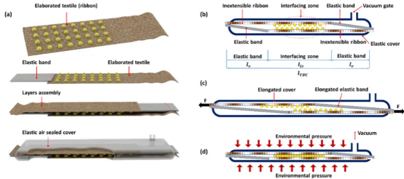
to the wearer body by the use of intrinsically soft and light structural materials (e.g., textiles and soft
44
elastomers) and soft actuation technologies [16]. Yet, most of the unpowered soft exosuits still include
45
clutching systems that are mainly based on rigid, bulky and heavy conventional clutches [17]. An
46
example of flexible clutch, based on electro-static force for quasi-passive ankle foot orthosis
47
exoskeletons, is presented in [11]. Still, the need of rigid and planar connection plates at each end for
48
guarantying the parallel gap between electrodes induces a certain level of rigidity; also, the use of
49
high voltage for wearable devices can cause safety problems. To address these issues (i.e., wearability,
50
comfort and safety), here we propose an entirely soft textile-based clutch actuated by vacuum sources
51
with unconventional load capabilities.
52
The power of vacuum is extensively exploited in several soft robotic technologies for two main
53
areas of applications: actuation [18-20] and variable stiffness solutions [21,22]. The successful use of
54
vacuum in a granular jamming based universal gripper [21], has motivated many other researches in
55
exploiting a similar approach to tune the stiffness in soft structures for a plethora of applications,
56
such as medical [23], and adaptive grasping [24]. Variable stiffness sleeves based on the jamming
57
mechanism of rubbery granules under vacuum are proposed in [22] for stiffening wearer body joints
58
in a soft exoskeleton. Similarly, in the layer jamming mechanism, the vacuum power pushes the
59
internal layers of a soft multi-layer structure together and converts it to a relatively stiff body. This
60
clutch like solution is also exploited in different fields, such as medical [25] and wearable robotics
61
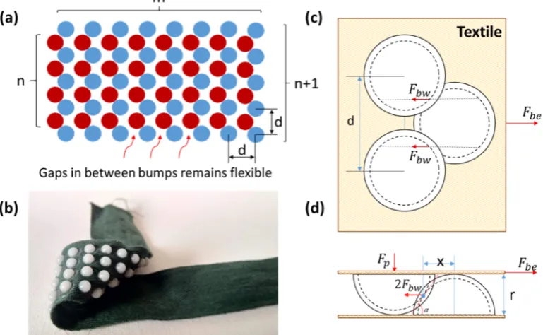
[26-29]. Although both the granular and layer jamming mechanisms have demonstrated promising
62
variation of stiffness for different soft robotic applications, increasing the final stiffness of a structure
63
by playing only on the amount of granules or layers result in bulky and heavy structures with higher
64
stiffness not only in the active but also in the passive mode.
65
In this work, we introduce the design and development of a new soft robotic component, which
66
is a textile-based clutch (TBC) that exploits vacuum as activation solution. TBC is highly compliant,
67
lightweight, compact and soft clutch realized with low cost components (i.e., textile, plastic, silicone).
68
High softness and adaptability with wearable technologies, combined with easiness of integration
69
with other materials commonly used in soft robotic structures (e.g., silicone elastomers), motivate the
70
use of textile as base material for the realization of TBC. With the aim of improving the blocking
71
capabilities of TBC, the surface of textile layers is elaborated by integrating miniature plastic
72
structures able to create an interlocking action between them. A comparison with other solutions
73
based on high friction materials (to improve the blocking force) is also performed, demonstrating the
74
effectiveness of the proposed solution. Activation strategies were also proposed and analyzed to
75
improve the response time of TBC.
76
2. Materials and Methods
77
2.1 Textile-Based Clutch
78
The soft TBC presented in this work is a bilayer elastic belt that we can block its elongation by
79
applying negative pressure (vacuum). TBC comprises two elaborated inextensible textile - woven
80
cotton - webbings, both in series with an elastic textile band. The two layers are connected together
81
from their heads by an inverse arrangement. Specifically, the head of each inextensible textile is fixed
82
to the head of the elastic band in the other series. Finally, the bilayer assembly of textile bands is
83
packed inside a flat and air sealed elastic cover that permits the easy elongation of the device (Figure
84
1a). In the passive or disengaged mode (Figure 1b and 1c), the two TBC layers can freely slide in front
85
of each other and consequently the TBC elongates with a minimum force that, based on Equation 1,
86
depends to the elasticity of the cover, elastic bands and frictional interaction between layers. The
87
application of a negative pressure inside the elastic cover activates the TBC (engaging mode) and
88
creates a temporary adhesion between textile layers (Figure 1d). In this mode, the flexibility of the
89
elastic cover permits that the external environmental pressure squeezes the cover and pushes the
90
inextensible textile webbings toward each other and causes their temporary and strong adhesion
91
(Figure 1d). The zone that the elaborated inextensible textile webbings face each other (called
92
presented in Equation 2 the magnitude of engaging force (F ) is a function of the applied
94
negative pressure (ΔP) and the device characteristics, such as the area occupied by the elastic bands
95
A , area of interfacing zone A , the frictional coefficient between textile layer and elastic bands
96
µ and the effect of elaboration technique µ ).
97
98
99
100
Figure 1. (a) CAD presentation of textile-based clutch TBC; two layers of textile parallel to each other
101
are encapsulated inside an elastic cover. (b) and (c) Textile layers can slide in front of each other by
102
means of an external elongation force; an elastic element in each layer of textile permits the device to
103
elongate and recover its initial configuration. (d) Connecting the TBC to a vacuum source permits to
104
the elaborated layers to create a temporary adhesion that blocks the elongation of the TBC under
105
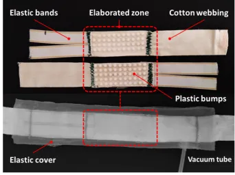
external elongation forces.
106
F F F , (1)
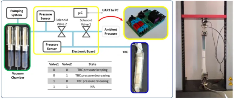
F ΔP A µ A µ , (2)
The elongation ratio (𝐸𝑅 ) is an important parameter to characterize TBC and it is defined as
107
the clutch elongation divided by the clutch length (𝑙 ). According to the design in Figure 1b, 𝑙
108
can be expressed as function of the length of interfacing zone (𝑙 ) and the length of elastic bands (𝑙 )
109
(Equation 3). The maximum elongation is physically limited by the elongation ratio of the elastic
110
bands (𝐸𝑅 ), but practically, for elongations greater than 𝑙 , the device cannot guarantee a proper
111
engaging force and, in this situation, the interlocking of elaborated parts is not guaranteed. The 𝐸𝑅
112
and 𝐸𝑅 conditions that guarantee the TBC blocking for each elongation are defined in Equation
113
4. However, depending to the application of TBCs a longer elastic band can be selected where longer
114
elongation range or lower elongation force during the disengaging mode is required.
115
𝑙 𝑙 2 𝑙 , (3)
𝐸𝑅 𝑙 ⁄𝑙 , 𝐸𝑅 𝑙 ⁄𝑙 , (4)
A second characterizing parameter of TBC is the withstanding force in the engaged mode. This
116
force can be modified by elaborating the frictional properties at interfacing zone. Utilizing materials
117
with high coefficient of friction (e.g. rubber coating) on the surface of inextensible textile can enhance
118
the TBC engaging performance without influencing the flexibility of the device. In this work, small
119
and rigid segments (called bumps) integrated on the surface of inextensible textiles are used to permit
120
a mechanical interlocking of the two textile layers to improve the withstanding force. This solution
121
improves the clutching performance by adding the force of mechanical interlocking to the just
122
frictional based force of engaging. Similar to the teeth in a dog clutch [30], the rigid bumps on each
123
interlocking action used for blocking the TBC elongation (Figure 1). Elaboration of the webbings by
125
this technique does not interfere with their flexibility as the bumps are integrated in an array format
126
(Figure 2a). This is because the area occupied by the rigid bumps in the array is small and the textile
127
in the gap between the segments remains flexible (Figure 2b). Both geometry and frictional property
128
of the bumps can influence the result of interlocking action during the engaging mode. In this work
129
we selected a semispherical geometry for the bumps. During the disengage mode, bumps with
130
semispherical shape easily slide on top of each other and do not significantly affect the elongation
131
force. In the engaging mode (vacuum applied), each single bump is subjected to a normal force
132
generated by the pressure and penetrates inside the front array of bumps, creating an engaging action
133
that resists to the sliding of bumps on top of each other. In an array of semispherical interlocking
134
bumps when all the bumps are penetrated inside each other the interlocking force can be obtained
135
by Equation 5.
136
137
Figure 2. (a) The bumps of one layer (blue) inter to the gap between bumps of the front layer (red)
138
and create an interlocking interaction. (b) A prototype of bumps array integrated on the surface of
139
cotton webbing; the textile remains flexible after the bumps integration. (c) and (d) The top and side
140
views of one bump interlocked with two bumps in the front layer; under force of environmental
141
pressure 𝐹 (generated by the vacuum), each bump can withstand the engaging force of 𝐹 which
142
is the sum of two forces 𝐹 acting on the bumps contacting points.
143
According Equation 5 and Equation 6, the size of bumps (r, the radius of semi-spheres), number
144
of bumps in array (n×m), their distance (d) and their frictional properties (µ) can affect the
145
withstanding force. Larger size of bumps can generate larger normal force caused by environmental
146
pressure during the vacuum and consequently result bigger withstanding force, which is also
147
influenced by the number of bumps as it is a sum of each bump engaging force (Figure 2). According
148
to Equation 6 shorter is the distance d bigger is the engaging force. The x in this equation is the
149
distance between the contact point of interlocked bumps and the center of each bump. Moreover, the
150
distance of bumps should also satisfy the condition in Equation 7, otherwise no interlocking between
151
bumps of two arrays is guaranteed. A tradeoff for the size of bumps is required, as the larger bumps
152
can transform the environmental pressure to a higher normal force while smaller bumps permit to
153
integrate higher number of bumps in a constant area of interfacing zone. The influence of size and
154
density of bumps are investigated in our prototypes and experimental studies, which are reported in
155
F ∆P A µ 𝑚 × 𝑛 × 𝜋𝑟 × 2𝐹 × 𝑡𝑎𝑛 ∝ 𝜇
1 𝜇 𝑡𝑎𝑛 ∝ , (5)
𝑡𝑎𝑛 ∝ , 𝑥 , (6)
𝑑 2√3 𝑟 (7)
157
Figure 3. The process of bumps integration on textile: The metallic mold is pre heated (a) then the
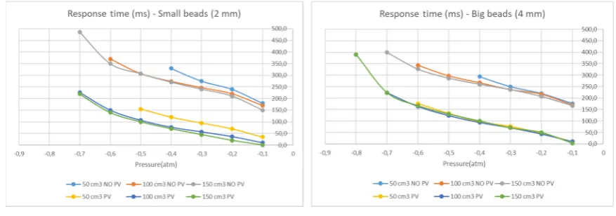
158
plastic pellets are added on it (b) and fused (c). After that, the fused material is pressed inside the
159
mold by a roller (d) till a homogeneous flat surface is obtained (e). On that surface is then lie down
160
the textile webbing (f) and the bumps are transferred on it (g). (k) Big bumps prototype. (i) Big bumps
161
mold. (l) Small bumps prototype; (j) Small bumps mold.
162
2.2 Prototyping
163
We combined different techniques such as embossing, casting, and sewing to develop the TBC
164
prototypes (Figure 3a to 3g). For each clutch, the arrays of rigid bumps were directly fabricated on a
165
pair of woven cotton webbings (0.5 mm thickness and 30 mm width). Two series of TBC prototypes
166
with semispherical bumps of 4 mm and 2 mm diameter were realized. The bumps were directly
167
shaped and integrated on the textile webbings by CNC milled aluminum molds (Figure 3i and 3j).
168
The metallic molds permit the fast and accurate realization of bumps array in one shot of pressing
169
action. The granules of polyoxymethylen (POM) thermoplastic with high stiffness, and excellent
170
dimensional stability [31], was firstly poured into the preheated (270°C) aluminum mold (Figure 3a
171
and 3b). After fusing of granules, they were pressed inside the mold semispherical cavities by rolling
172
a metallic cylinder over fused materials since a thin, flat and homogenous layer was obtained (Figure
173
3c to 3e and Supplementary Video1). The bumps inside the aluminum mold were transferred to the
174
cotton webbing by locating the webbing on the top of the array and pressing it toward melted
175
polymer, again by rolling of the metallic cylinder (Figure 3f). By pressing, the melted thermoplastic
176
penetrates inside the textile porous texture and creates a strong bonding that is unified by the bump
177
material. Finally, the assembly was removed from the mold after cooling the mold by cold water
178
location under shear forces generated during the engaging action. TBCs with the 4 mm bumps
180
integrate arrays of 5×11 bumps in front of 4×11 with 6 mm distance between bumps (Figure 3k); TBCs
181
with 2 mm bumps were realized by arrays of 10×22 in front 9×22 with the distance of 3 mm in between
182
bumps (Figure 3l). The webbings with one column less of bumps permit a symmetric configuration
183
of webbings in the final assembly as the bumps of each webbing seats in the free space between
184
bumps of the other webbing. An elastic textile band with 15 mm width and maximum 120% of
185
elongation (Super-Elastic Prym Co.) was sewed to one head of each elaborated webbing. Sewing was
186
selected as one of the best techniques that can adapt to the textile without affecting its properties or
187
generating any rigidity in the connection point of elastic and non-elastic bands while providing a
188
strong bonding. The total practical length of all the TBC prototypes was 180 mm while the length of
189
interfacing area was 60 mm. For all the prototypes an elastic cover larger than the textiles assembly
190
was realized by a casting process of silicone elastomer (Ecoflex 0030 of Smooth-On Co.) with a
191
rectangular shape (50×220 mm, with 1 mm of wall thickness). Whole assembly of textile bands were
192
inserted and sealed inside the elastic covers (Figure 4). A 4 mm silicone tube (SAINT-GOBAIN Co.)
193
was later integrated to the elastic cover by silicone caulk.
194
Two other series of clutches based on just frictional materials were realized in order to compare
195
the results with the TBC prototypes based on interlocking. Their interfacing zones were elaborated
196
with high frictional coefficient materials: one by adhering sandpaper (P600) on the top and bottom
197
sides of the interfacing zone; the second by coating 0.5 mm of silicone rubber at the interfacing zone
198
which was achieved by direct sinking of textile webbing in silicone elastomer (Ecoflex 0030,
Smooth-199
On, Inc.).
200
201
202
Figure 4. (top) The internal layers of TBC with elastic bands, elaborated zone with rigid bumps and
203
inextensible cotton webbing; (bottom) Final assembled TBC inside the air sealed silicone rubber cover.
204
2.3 Clutch control unit
205
In order to address the requirements of compactness and mobility in wearable devices we
206
developed a miniature pneumatic circuit that is managed by a custom control unit. A microcontroller
207
(TMS320F28035 from Texas Instruments, Dallas, USA) regulates the pressure inside the TBC through
208
two pneumatic valves (TX3P030LV03LN from First Sensor AG, Berlin, Germany) and a pressure
209
sensor (MPXV6115V from NXP Semiconductor, Eindhoven, Netherlands). One of the two valves
210
(Valve 1 in Figure 5) connects the clutch to the ambient pressure for the disengaging mode, while the
211
pressure sensor is located between Valve2 and vacuum chamber to monitor the pressure of the
213
chamber. A PC is connected to the setup by a serial interface (UART) to set the clutch pressure and
214
acquire the pressure monitored by the system. A control loop is implemented in the microcontroller
215
to keep the set pressure. Normally, both valves are deactivated; in this condition the clutch is closed
216
and the pressure inside is kept to the reached value. We added a hysteresis of ±0.01 bar to the set
217
value to avoid unnecessary valves activation and waste of energy. We used a vacuum chamber as
218
vacuum reservoir that decouples the pump speed from the actuator speed. The vacuum chamber is
219
brought to the desired vacuum level by the pumping system and then switched off. The developed
220
system was used to characterize the clutch in terms of force and response time. In a real application,
221
a constant pressure inside the reservoir can be guaranteed by the same control unit and by monitoring
222
the pressure sensor between Valve 2 and reservoir.
223
224
225
Figure 5. (left) Schematic of the control unit; two valves control the pressure inside the TBC. A
226
chamber is used as vacuum reservoir and provides the possibility of several activation of TBC without
227
direct use of vacuum pump; (right) Mechanical testing machine used to experimentally evaluate the
228
TBC engaging force.
229
2.4 Experimental protocols and setups
230
Two sets of experiments were performed on the TBC prototypes to characterize their
231
withstanding force under different conditions and their response time during engaging and
232
disengaging actions. The force-elongation tests were performed by a material testing machine
233
(Zwick/Roell Z005) and the pneumatic circuit discussed in the previous section to set the pressures
234
in the TBCs (Figure 5 - right). We evaluated the engaging forces of all the TBC prototypes (friction
235
based and interlocking based) under different negative pressures: 0 atm (no vacuum) to -0.8 atm with
236
0.2 atm steps, for 25 mm elongation with 100 mm/min linear velocity. The tests with no vacuum
237
pressure (0 atm) were performed to measure the minimum force required for the elongation of TBCs
238
in the disengaged mode. In order to clarify the frictional effect of the elaboration solutions on the
239
minimum elongation force and separate it from the effect of elastic bands and the elastic covers, the
240
elongation force of elastic cover and elastic bands were also separately characterized. The
241
experiments were repeated for five times for three samples of each prototype. The response times of
242
the interlocking TBC clutches for both engaging and disengaging actions can be affected by several
243
aspects such as size of TBC clutches, volume and pressure level of the vacuum chamber, valves
244
dimension, length and size of the pneumatic circuit and the desired final pressure level for the TBC.
245
We evaluated the TBCs speeds with the same compact and portable control unit considering that one
246
of the main applications of the clutch would be in soft exosuits where compactness, low weight and
247
wearability are demanded. These measurements were made by evaluating the rate of pressure
248
variation inside TBC during its activation. In order to investigate the influence of reservoir capacity
249
on the response time of TBCs the experiments were repeated for three different sizes of vacuum
250
the desired vacuum was achieved, the vacuum pump was disconnected from the chamber to exclude
252
the performance of the pump from the reservoir effect. The disengaging response time were
253
evaluated by connecting TBCs to a constant pressure of -0.8 atm (as maximum achieved negative
254
pressure) and measuring the time needed to reach the ambient pressure one time Valve1 was open.
255
To accelerate the response of TBCs with soft inflatable silicone covers, we hypothesized that
pre-256
charging the device with a small negative pressure during the disengaging mode can reduce the
257
device internal volume by deflating the cover and consequently reducing the engaging response time
258
while the small negative pressure does not influence significantly the minimum elongation force in
259
this mode. We experimentally evaluated this technique by applying small vacuum values while
260
measuring the minimum elongation forces. Later based on this experiment, we evaluated the
261
response time of TBCs when they were pre-charged by this negative pressure. All the experiments
262
were repeated 5 times for each testing condition
263
3. Results & Discussion
264
In the tests at ambient pressure (0 atm) all the devices demonstrated a similar elongation force
265
of 14.9 N, 15.7 N, 14.4 N, 15.1 N respectively for small bumps, large bumps, sand paper and silicone
266
rubber coating. Comparing these measures with the elongation force of just the elastic bands together
267
with elastic cover (14 N), we observed that large portion of elongation forces during disengaging
268
mode is dedicated to the properties of elastic elements instead of the effect of frictional properties of
269
elaborated techniques.
270
All the tested negative pressures were able to block the elongation of the interlocking TBC with
271
different withstanding forces. As expected the highest maximum force was obtained with the TBCs
272
elaborated by interlocking bumps. Both of the interlocking prototypes with small and large bumps
273
presented better performance in comparison with friction-based TBCs (Figure 6 left). The average
274
maximum withstanding force of small and large bumps interlocking TBCs were 150.5 N, 152.6 N,
275
respectively, in correspondence of -0.8 atm for 25 mm elongation of TBC. In these prototypes the
276
number of bumps (𝑚 × 𝑛) multiplied for the area of each bump (𝜋𝑟 ) is almost the same. This justifies
277
(equation 5) why we a big difference of withstanding force between them was not measured. The few
278
differences of these measures would be due to the less conformability of silicone cover into the small
279
gaps in between the small bumps, in comparison with the larger gaps in between the bigger bumps.
280
The maximum measured forces for the TBC samples with sand paper and silicone coating were 138.7
281
N and 54.8 N under the same negative pressure (-0.8 atm).
282
283
At the beginning of each blocking test, we observed 12-15 mm extension of the textile webbings
284
and therefore the first breaking of engaging action happened after that initial stretch of the textile.
285
The force-displacement graphs of interlocking TBCs (Figure 6 middle and Figure 6 right) demonstrate
286
the locking action of these type of clutches in the smallest vacuum pressure (-0.2 atm) and biggest
287
vacuum pressure (-0.8 atm). The picks in these graphs relate to the moment that interlocking action
288
of clutch fails and the bumps slide on top of each other and again seat inside the gap between them
289
and the device recovers its locking action. For this reason, the distance between picks of the graphs
290
corresponds the distance of bumps in the array of each prototype, which is 3 mm for the array with
291
small bumps and 6 mm for the array with larger bumps. All TBCs, even after breaking the
292
withstanding force, continue to elongate with an increasing force, which is due to the effect of elastic
293
elements (elastic bands and elastic cover) as well as to an enlargement of the TBC area during
294
elongation that results in a larger normal force generated by environmental pressure. Similarly, the
295
proper action of the TBCs elaborated by sand paper was visible when the elongation of inextensible
296
textile was stopped. This clutch, after its first breaking, demonstrated an engaging and disengaging
297
behavior with very small picks in the force-displacement graph affected by miniature bumps of sand
298
paper roughness. Differently, with the interlocking TBCs and sand paper the TBCs elaborated by
299
silicone rubber without any clear breaking moment just demonstrated a growing force when the
300
extension of the cotton webbing was finished. This clutch demonstrated a lower withstanding force
301
maximum measured force was much higher than minimum measured force (disengaging mode) in
303
ambient pressure.
304
305
Figure 6. (Left): The mean maximum withstanding force of all the tested samples under different
306
applied pressures (standard deviation ±1-3 N). (Middle) the force-displacement graph of all the TBCs
307
under -0.2 atm and (right) under -0.8 vacuum pressure.
308
309
Figure 7. (left) the engaging response time of TBCs with small bumps; (right) the engaging response
310
time of TBCs with large bumps (standard deviation ±3-8 ms). Both types of samples were tested in
311
two different conditions; one starting from ambient pressure and one starting with a pre-charged
312
pressure of -0.01 atm.
313
314
The results of the TBCs response time with small and rigid bumps and in engaging mode from
315
environmental pressure to the different target pressures are depicted in (Figure 7 - left). We measured
316
a slightly faster response time in the case of reservoirs with bigger volume. Also the TBC with bigger
317
bumps was generally faster than the TBC with smaller bumps, probably because the elastic cover
318
adapts easier in the large gap between large bumps (Figure 7 - right). The use bigger reservoirs
319
allowed obtaining a better performance in achieving higher negative pressure inside TBCs. Therefore,
320
in the case of applications that require high withstanding forces and consequently higher pressures,
321
a bigger reservoir would be a good selection. We also recorded a faster response time in the
322
experiments where TBCs were pre-vacuumed (internal pressure was set to -0.01 atm). The target
323
pressure in the case of pre-vacuum was generally achieved 160 ms faster. For example, in the test
324
with the slowest speed, TBC with large bumps took 350 ms to reach -0.6 atm while the same pressure
325
was achieved in 160 ms in the case of pre-vacuum (190 ms faster). In general, the average response
326
time of TBCs with small and large bumps respectively varies between 170-370 ms and 170-343ms in
327
the normal case while by setting a pre-vacuum inside the clutches these range decrease to 3.3-226 ms
328
and 10-223 ms for reaching -0.7 atm (with the chamber of 100 ml). This is while the elongation force
329
does not show a significant difference between the -0.01 atm (19-20 N) and 0 atm (15-16 N) conditions.
330
In addition to TBC performance, all of these results are also influenced by the performance of the
331
About the disengaging mode, we recorded an average response time of 200 ms and 210 ms
333
respectively for the TBCs with small and large bumps. The discharge response time also can become
334
faster by blowing air inside the clutch, assisting the disengaging phase by a positive pressure.
335
4. Conclusions
336
In this work, we present a flat, compact and powerful soft clutching device that exploits intrinsic
337
flexibility of textiles and silicone elastomers in its structural materials. The proposed component can
338
simulate the functionality of conventional clutches and break in soft-bodied structure while it also
339
has the capability of conformation and adaptation to different shapes. The textile-based clutches, i.e.,
340
TBCs, present a maximum withstanding force of 152 N, which is obtained using two layers of textile.
341
TBCs also demonstrate a high withstanding-weight ratio of 340 times, considering the average weight
342
of 45 g for all the developed prototypes. In addition to the interlocking TBCs, a series of friction-based
343
clutches with coating of sand paper and silicone rubber were developed and characterized. The TBC
344
elaborated by sand paper also demonstrated an acceptable performance with high withstanding force
345
(average maximum of 138N), the practical issue with this type of TBC is the fast wear of sand paper
346
under shear force and lose of performance after few cycle of use. Instead, the friction-based TBC
347
developed by coating silicone on textile was the weakest TBC among other prototypes with
348
maximum withstanding force of 54N. In contrast with interlocking TBCs, the silicone-coated TBC
349
elongates smoothly with different forces under different applied negative pressures. Due to this
350
behavior, the rubber-coated TBC can be potentially used as a variable stiffness elastic component
351
with an elasticity that is tunable with pressure. The small size of TBCs results in a low internal volume
352
that provides the possibility of achieving quite fast response time (in the order of 200 ms), even with
353
a small and lightweight vacuum system. The high elongation ratio of the proposed device (up to 33
354
%) and the relatively fast response time of the clutches broaden its application in many different fields
355
of application, such as wearable robotics. As example, the TBCs clutches can be integrated in a soft
356
exosuit to limit and controlling the joints motions for assistive and rehabilitation applications [32]. In
357
such application, the flat configuration and softness of developed clutch permit high adaptability to
358
the wearer body and ease integration to textile based garments. Moreover, combination of this device
359
in parallel or series with other elastic elements permits to engaging and disengaging or bypassing
360
elastic elements in robotic structures that can have many applications in impedance control scenarios
361
in legged robots and in unpowered exoskeletons and exosuits. The compact size of each TBC permits
362
parallel configuration of several TBCs in a compact or flat assembly, which results greater
363
withstanding forces for the case that loads higher than a single TBC is required. Moreover, as future
364
work we aim to investigate the effect of different bump shapes and patterns on the performance of
365
TBCs.
366
Supplementary Materials: The following are available online at www.mdpi.com/xxx/s1, Video S1: Clutch
367
Fabrication, Video S2: TBC disengaged mode, Video S3: TBC weight lifting.
368
Author Contributions: “conceptualization, A.S.; methodology, A.S., A.M.; validation, A.S., A.M.; writing—
369
original draft preparation, A.S.; writing—review and editing, A.S., A.M., B.M.
370
Funding: This work has received funding from the European Union’s Horizon 2020 framework programme for
371
research and innovation under grant agreement No 688175.
372
Conflicts of Interest: “The authors declare no conflict of interest.” “The funders had no role in the design of the
373
study; in the collection, analyses, or interpretation of data; in the writing of the manuscript, or in the decision to
374
publish the results”.
375
376
References
377
1. Plooij, M.; Mathijssen, G.; Cherelle, P.; Lefeber, D.; Vanderborght, B. Lock your robot: A review of
378
locking devices in robotics. IEEE Robotics & Automation Magazine 2015, 22, 106-117.
379
2. Karbasi, H.; Huissoon, J.P.; Khajepour, A. Uni-drive modular robots: theory, design, and experiments.
380
3. Murata, S.; Kurokawa, H.; Yoshida, E.; Tomita, K.; Kokaji, S. A 3-D self-reconfigurable structure. In
382
Proceedings of Robotics and Automation, 1998. Proceedings. 1998 IEEE International Conference on;
383
pp. 432-439.
384
4. Aukes, D.M.; Heyneman, B.; Ulmen, J.; Stuart, H.; Cutkosky, M.R.; Kim, S.; Garcia, P.; Edsinger, A.
385
Design and testing of a selectively compliant underactuated hand. The International Journal of Robotics
386
Research 2014, 33, 721-735.
387
5. Lauzier, N.; Gosselin, C. Series clutch actuators for safe physical human-robot interaction. In
388
Proceedings of Robotics and Automation (ICRA), 2011 IEEE International Conference on; pp.
5401-389
5406.
390
6. Armour, R.; Paskins, K.; Bowyer, A.; Vincent, J.; Megill, W. Jumping robots: a biomimetic solution to
391
locomotion across rough terrain. Bioinspiration & biomimetics 2007, 2, S65.
392
7. Kim, K.-S.; Kim, B.-S.; Song, J.-B.; Yim, C.-H. Mobility improvement of a jumping robot using conical
393
spring with variable length endtip. Journal of Institute of Control, Robotics and Systems 2009, 15,
1108-394
1114.
395
8. Zaitsev, V.; Gvirsman, O.; Hanan, U.B.; Weiss, A.; Ayali, A.; Kosa, G. A locust-inspired miniature
396
jumping robot. Bioinspiration & biomimetics 2015, 10, 066012.
397
9. Collins, S.H.; Wiggin, M.B.; Sawicki, G.S. Reducing the energy cost of human walking using an
398
unpowered exoskeleton. Nature 2015, 522, 212.
399
10. Walsh, C.J.; Endo, K.; Herr, H. A quasi-passive leg exoskeleton for load-carrying augmentation.
400
International Journal of Humanoid Robotics 2007, 4, 487-506.
401
11. Diller, S.; Majidi, C.; Collins, S.H. A lightweight, low-power electroadhesive clutch and spring for
402
exoskeleton actuation. In Proceedings of Robotics and Automation (ICRA), 2016 IEEE International
403
Conference on; pp. 682-689.
404
12. Yakimovich, T.; Kofman, J.; Lemaire, E.D. Design and evaluation of a stance-control knee-ankle-foot
405
orthosis knee joint. IEEE Transactions on neural systems and rehabilitation engineering 2006, 14, 361-369.
406
13. Muhammad, I.; AO, N.A. Stance-Control-Orthoses with Electromechanical Actuation Mechanism:
407
Usefulness, Design Analysis and Directions to Overcome Challenges. Journal of Neurology and
408
Neuroscience 2015, 6.
409
14. Chen, J.; Liao, W.-H. A leg exoskeleton utilizing a magnetorheological actuator. In Proceedings of
410
Robotics and Biomimetics, 2006. ROBIO'06. IEEE International Conference on; pp. 824-829.
411
15. Nikitczuk, J.; Weinberg, B.; Canavan, P.K.; Mavroidis, C. Active knee rehabilitation orthotic device
412
with variable damping characteristics implemented via an electrorheological fluid. IEEE/ASME
413
Transactions on Mechatronics 2010, 15, 952-960.
414
16. Asbeck, A.T.; De Rossi, S.M.; Holt, K.G.; Walsh, C.J. A biologically inspired soft exosuit for walking
415
assistance. The International Journal of Robotics Research 2015, 34, 744-762.
416
17. Poliero, T. Soft wearable device for lower limb assistance: assemsment of an optimized energy efficient
417
actuation prototype. Soft Robotics 2018, Livorno 2018.
418
18. Robertson, M.A.; Paik, J. New soft robots really suck: Vacuum-powered systems empower diverse
419
capabilities. Sci. Robot. 2017, 2, eaan6357.
420
19. Yang, D.; Verma, M.S.; Lossner, E.; Stothers, D.; Whitesides, G.M. Negative‐Pressure Soft Linear
421
Actuator with a Mechanical Advantage. Advanced Materials Technologies 2017, 2.
422
20. Li, S.; Vogt, D.M.; Rus, D.; Wood, R.J. Fluid-driven origami-inspired artificial muscles. Proceedings of
423
the National Academy of Sciences 2017, 201713450.
424
21. Brown, E.; Rodenberg, N.; Amend, J.; Mozeika, A.; Steltz, E.; Zakin, M.R.; Lipson, H.; Jaeger, H.M.
425
Universal robotic gripper based on the jamming of granular material. Proceedings of the National
426
Academy of Sciences 2010, 107, 18809-18814.
427
22. Hauser, S.; Robertson, M.; Ijspeert, A.; Paik, J. Jammjoint: A variable stiffness device based on granular
428
jamming for wearable joint support. IEEE Robotics and Automation Letters 2017, 2, 849-855.
429
23. Ranzani, T.; Gerboni, G.; Cianchetti, M.; Menciassi, A. A bioinspired soft manipulator for minimally
430
invasive surgery. Bioinspiration & biomimetics 2015, 10, 035008.
431
24. Wei, Y.; Chen, Y.; Ren, T.; Chen, Q.; Yan, C.; Yang, Y.; Li, Y. A novel, variable stiffness robotic gripper
432
based on integrated soft actuating and particle jamming. Soft Robotics 2016, 3, 134-143.
433
25. Kim, Y.-J.; Cheng, S.; Kim, S.; Iagnemma, K. A novel layer jamming mechanism with tunable stiffness
434
capability for minimally invasive surgery. IEEE Transactions on Robotics 2013, 29, 1031-1042.
435
26. Bureau, M.; Keller, T.; Perry, J.; Velik, R.; Veneman, J.F. Variable stiffness structure for limb attachment.
436
In Proceedings of Rehabilitation Robotics (ICORR), 2011 IEEE International Conference on; pp. 1-4.
437
27. Choi, I.; Corson, N.; Peiros, L.; Hawkes, E.W.; Keller, S.; Follmer, S. A Soft, Controllable, High Force
438
28. Sadeghi, A.; Mondini, A.; Mazzolai, B. Preliminary Experimental Study on Variable Stiffness
440
Structures Based on Textile Jamming for Wearable Robotics. In Proceedings of International
441
Symposium on Wearable Robotics; pp. 49-52.
442
29. Tonazzini, A.; Shintake, J.; Rognon, C.; Ramachandran, V.; Mintchev, S.; Floreano, D. Variable stiffness
443
strip with strain sensing for wearable robotics. In Proceedings of 2018 IEEE International Conference
444
on Soft Robotics (RoboSoft); pp. 485-490.
445
30. MASc, T.Y.; Jonathan Kofman PhD, P. Engineering design review of stance-control knee-ankle-foot
446
orthoses. Journal of rehabilitation research and development 2009, 46, 257.
447
31. Visakh, P.; Chandran, S. Polyoxymethylene Handbook: Structure, Properties, Applications and Their
448
Nanocomposites; John Wiley & Sons: 2014.
449
32. Ortiz, J.; Rocon, E.; Power, V.; de Eyto, A.; O’Sullivan, L.; Wirz, M.; Bauer, C.; Schülein, S.; Stadler, K.S.;
450
Mazzolai, B. Xosoft-a vision for a soft modular lower limb exoskeleton. In Wearable Robotics: Challenges