THE SOLUTION OF THE TWO-DIMENSIONAL INVERSE HEAT
TRANSFER PROBLEM WITH THE USE OF THE FEM
IN COMBINATION WITH TREFFTZ FUNCTIONS
Magdalena PIASECKAx1, Beata MACIEJEWSKAx2
Abstract: The aim of this paper is to determine the boiling heat transfer coefficient for the cooling liquid flow in a rectangular minichannel with asymmetric heating. The main part of the test section is made up of a vertical minichannel of 1.0 mm depth. The heating foil on the side of the fluid flowing in the minichannel is single-sided enhanced on the selected area. The experiment is carried out with FC-72. The investigations focus on the transition from single-phase forced convection to nucleate boiling, that is, from the zone of boiling incipience further to developed boiling. Owing to the liquid crystal layer located on the heating surface contacting the glass, it is possible to measure the heating wall temperature distribution while increasing the heat flux transferred to the liquid flowing in the minichannel. The objective of the calculations is to evaluate a heat transfer model and numerical approach to solving the inverse boundary problem, and to calculate the heat transfer coefficient. This problem has been solved by means the finite element method in combination with Trefftz functions (FEMT). Trefftz functions are used to construct base functions in Hermite space of the finite element.
NOMENCLATURE
A, B, C, a, b, c – linear combination coefficient,
J – error functional,
L – minichannel length, m,
lw – number of nodes in an element,
P – number of measurement points,
BI – boiling incipience,
V
q
– volumetric heat flux (capacity of internal heat source), W/m3,T – temperature, K,
y
x
T
~
,
– temperature approximate, K,)
,
(
x
y
u
– particular solution of the non-homogeneous equation,)
,
(
x
y
v
– Trefftz functions,y
x
,
– spatial coordinates,
x1 Kielce University of Technology, Faculty of Mechatronics and Machine Building, Chair of
Mechanics, al. 1000-lecia P.P.7, 25-314 Poland; email: [email protected]
x2 Kielce University of Technology, Faculty of Management and Computer Modelling
, Chair of Mathematics, al. 1000-lecia P.P.7, 25-314 Poland; email: [email protected]
Greek letters
:
– flat domain,D
– heat transfer coefficient, W/(m2K),G
– depth, m,)
,
(
x
y
M
,
I
x,
y
,
\
x,
y
– base functions,
O
– thermal conductivity, W/(mK),Indexes
l – liquid,
F – foil,
G – glass,
i, j, k, n– numbers,
p – measurement point.
1. I
NTRODUCTIONTransferring large heat fluxes is one of the most significant issues of today’s technology. An increasing number of high-tech heat exchange devices are based on heat transfer to fluid during flow boiling in minichannels of various geometry. Owing to the change of state that accompanies boiling, it is possible at the same time to meet two contradictory demands: to obtain the largest possible heat flux at small temperature difference between the heating surface and the saturated liquid, and to keep small dimensions of heat transfer systems.
The heat transfer considerations presented in this article focus on heat transfer coefficient identification, which belongs to the group of inverse heat conduction problems [1,7,8]. Both the inverse problem and the auxiliary direct problem were solved by means of the Trefftz method. The idea of this method was presented in [14] and consists in representing the approximate solution to the problem as a linear combination of functions which satisfy the governing equation strictly and the set boundary conditions approximately. Additional information on the Trefftz method is included in [2,4,6,15].
2. M
AIN GOALThe objectives of the experimental investigations and calculations discussed in the present article are evaluation of a heat transfer model and numerical approach to solving the inverse boundary problem, and calculation of local heat transfer coefficient using FEM method with Trefftz functions. The application of liquid crystal thermography enables determination of two-dimensional temperature distribution on the heating surface which is single-sided enhanced on the selected area.
3. E
XPERIMENTAL SET-
UPminichannel. The main loop of the experimental stand, the test section with the minichannel and the image and data acquisition systems are described in detail in [9] this collection of conference papers.
6
7
7
3
4
5
1
2
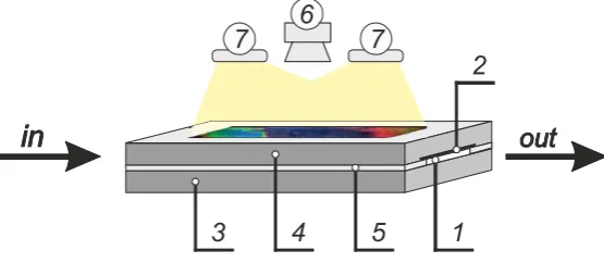
Figure 1: The schematic diagram of the test section: #1-minichannel, #2- heating foil with liquid crystals, #3,#4- metal cover with a sight glass, #5-side walls of the minichannel, made of PTFE, #6-camera, #7-lighting system
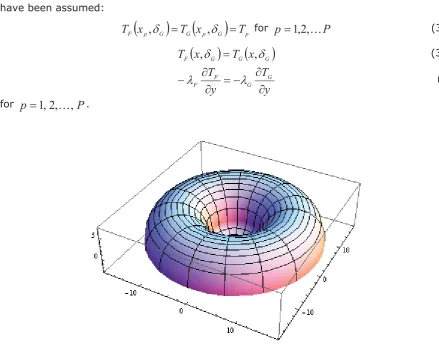
On the selected area of the heating foil (Fig. 2) micro-recesses were formed and distributed evenly. The micro-recesses, made with a laser device are 3 Pm deep evenly distributed every 100Pm in both axes. The depth of the micro-recesses depends on the parameters of the laser energy settings. A 7Pm high layer of melted metal, locally 5-10Pm high, accumulates annularly around the micro-recesses. Total height of the microrecess (structure) with a crater is about 10Pm. Total diamater of the microrecess (structure) with a crater is about 30Pm. Figure 3 shows 3D surface topographies of the foil area with a microrecess system (Fig. 3a) and an example of a single microrecess (Fig. 3b). The 3D surface topographies were prepared by means of Taylor Hobson Form Talysurf PGI-1200 measuring system at Kielce University of Technology.
a)
b)
4. T
WO-
DIMENSIONAL MODEL4.1. P
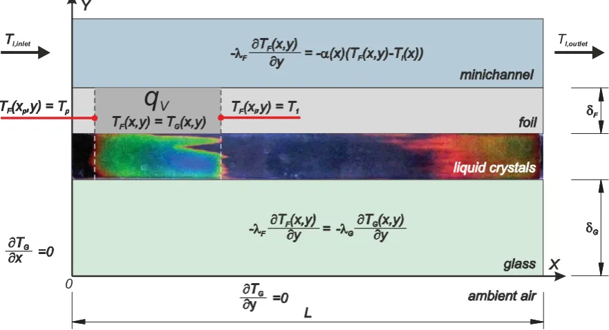
ROBLEM FORMULATIONIn a two-dimensional approximation of heat flow through major elements of the test section (Fig. 4), there occurs a simple problem in the glass barrier and an inverse problem in the heating foil [9,10]. To solve them, temperature measurements in the foil on the glass-side boundary, obtained thanks to the application of liquid crystal thermography, are used. When solving the inverse problem (no boundary condition on the boundary y=GG+GF), the temperature field and heat flux density in the foil on the boundary y=GG+GFare determined. Local values of heat transfer coefficient are calculated with the assumption of linear temperature distribution of the liquid flowing along the minichannel (measurement of the liquid temperature at minichannel inlet and outlet). It is assumed that in the foil operates a heat source of constant efficiency qV, distributed evenly in the entire volume of the foil. The heating foil is single-sided enhanced on the selected area on side of the fluid flowing in the minichannel. On the basis of the 3D enhanced surface topography for a single microrecess (see Fig. 3b) a mathematical model was developed, featured in Fig. 5.
0
q
Vl,inlet Tl,outlet
Figure 4: Boundary conditions for a two-dimensional approximation of heat flux across main elements of the test section
The temperature of the glass barrier
T
(
x
,
y
)
G satisfies the equation:
0
2
T
G(1)
where
x
,
y
:
G^
x
,
y
R
2:
0
x
L
,
0
y
G
G`
,
The temperature of the heating foil
T
(
x
,
y
)
F V F
q
T
O
2 (2)where
^
`
F G G
P
F
x
y
R
x
x
x
y
y
x
,
:
,
:
1,
G
G
G
2 ,
1
x
is the coordinate of the first temperature measurement,P
x
is the coordinate of the final temperature measurement.Moreover, for
G
y
G
and0
x
L
(the foil-glass boundary), the following conditions have been assumed: p G G p G pF
x
T
x
T
T
,
G
,
G
forp
1
,
2
,
P
(3a) G G GF
x
T
x
T
,
G
,
G
(3b)y
T
y
T
GG F
F
w
w
w
w
O
O
(4)for
p
1
,
2
,
,
P
.Figure 5: Mathematical model of a single microrecess of the enhanced foil
Conditions on other boundaries:
0
w
w
y
T
G for0
y
and0
x
L
(5)0
w
w
x
T
G for0
x
as well asx
L
andG
y
G
0
(6)1 1
,
)
(
x
y
T
T
F forG
Gy
G
GG
F (7)P P
F
x
y
T
T
(
,
)
forF G G
y
G
G
The problem thus formulated is solved by means of Trefftz functions (T-functions) [2,3,4,6,14,15]. These functions are used to solve both simple and the inverse problems. The basic property of Trefftz functions is satisfying the governing equation. In the problem under discussion, it is the Laplace equation (1). What remains to be done is to adjust the linear combination of Trefftz functions to required initial and boundary conditions, and – in the case of inverse problems – also to the measurements, e.g. temperature.
In order to determine the value of heat transfer coefficient on the boundary
F G
y
G
G
the temperature of the glass barrier
T
x
y
G
,
is first determined from the solution of a direct problem, and subsequently the foil temperatureT
x
y
F
,
is determined from the solution of the inverse problem. Knowing the foil temperature distribution enables the determination of local values of heat transfer coefficient on the heating foil–liquid boundary in the minichannel from the condition:x
T
x
T
x
y
x
T
l F G F F
G F
F
w
w
O
,
G
G
D
(
,
G
G
)
(9)where
D
is the sought heat transfer coefficient, andT
(
x
)
l is liquid temperature, approximated linearly along the entire minichannel length.
4.2. F
INITE ELEMENT METHOD WITH THE USE OFT-
FUNCTIONS(
FEMT)
The solution method for Eqs. (1) and (2) is a generalisation of the method presented in [3]. In order to solve the formulated problem, domains
G
:
and F:
are divided into elements jG
:
and j F:
. The approximate temperature in each element j G:
is shown as a linear combination of basis functions(
x
,
y
)
jk
M
,I
jkx
,
y
,\
jkx
,
y
:¦
lwk
jk n jk
n jk
n j
G
x
y
a
x
y
b
x
y
c
x
y
T
1
,
,
,
,
~
M
I
\
(14)where j is the element number, k is the node number in the jth element,
lw
is the number of nodes in the element, n is the node number in the entire domainG
:
,a
n denotes the approximate values of the glass temperature in nodes,b
n - the approximate values of the partial derivative of glass temperature with respect to x in nodes,c
n - the approximate values of the partial derivative of glass temperature with respect to y in nodes.The base functions
(
x
,
y
)
jkM
,I
jkx
,
y
,\
jkx
,
y
are a linear combinations of Trefftz functions and have the following properties in nodes:ki i i
jk
x
y
G
M
(
,
)
,(
,
)
0
w
w
i i jk
y
x
x
M
,0
)
,
(
w
w
i i jk
y
x
y
M
,lw
0
)
,
(
i ijk
x
y
I
, ki i i jky
x
x
G
I
w
w
)
,
(
,(
,
)
0
w
w
i i jky
x
y
I
,
i
1
,
2
,
,
lw
(15 b)0
)
,
(
i ijk
x
y
\
,(
,
)
0
w
w
i i jky
x
x
\
, ki i i jky
x
y
G
\
w
w
)
,
(
,i
1
,
2
,
,
lw
(15 c)where
G
ki-Kronecker delta. The base functions strictly satisfy Eq. (1)The unknown coefficients
a
n,
b
n,
c
n of the linear combination (14) are determined byminimization of the functional
J
:¦³
¦³
w
w
w
w
2 10 2 1 * ) 1 ( 1 2 0 2 1 * 1 1 1
))
,
(
~
(
))
,
0
(
~
(
L i y y L i G L i y y L i G i i i idy
y
L
x
T
dy
y
x
T
J
w
w
w
w
w
w
¦³
¦
¦³
¦
¦
¦³
1 1 1 2 1 * 1 1 * 1 2 : 0 1 1 1 2 1 * 1 1 * 1 2 : 0 2 1 1 1 2 1 1 1))
,
(
~
)
,
(
~
(
))
,
(
~
)
,
(
~
(
)
)
,
(
~
(
))
0
,
(
~
(
L j y y j L i j G j L i j G L i L j y y j L i j G j L i j G L i p G P p j G L j x x j G i i i i j j j jdy
y
x
x
T
y
x
x
T
dy
y
x
T
y
x
T
T
x
T
dx
x
y
T
G
¦
¦³
1 1 2 1 * 1 * ) 1 ( 1 2 :1 1
(
,
))
~
)
,
(
~
(
L j x x i L i j G i L i j G L i j jdx
y
x
T
y
x
T
¦
¦³
w
w
w
w
1 1 2 1 * 1 * ) 1 ( 1 2 :0 1
(
,
))
~
)
,
(
~
(
L j x x i L i j G i L i j G L i j jdx
y
x
y
T
y
x
y
T
(16)where L1 is the number of elements in the Ox axis direction, L2 is the number of
elements in the Oy axis direction.
In a similar way foil temperature is determined. In each element j F
:
, it is represented in the form of a linear combination of basis functions(
x
,
y
)
jk
M
,I
jkx
,
y
,\
jkx
,
y
with properties (15a-c)¦
lw k jk n n x n jk n n n jF
x
y
u
x
y
A
u
x
y
x
y
B
u
x
y
x
y
T
1 '(
,
)
,
,
)
,
(
)
,
(
,
~
M
I
C
nu
y(
x
n,
y
n)
jkx
,
y
'
\
(17)where
u
(
x
,
y
)
is a particular solution of the non-homogeneous equation, n is the nodenumber in the entire domain F
:
while j, k and lw have the same meaning as in formula (14).A
n are the approximate values of the foil temperature in nodes,B
n thenodes,
C
n the approximate values of the approximate partial derivative of foiltemperature with respect to y in nodes,
(
,
)
n n
y
x
u
is the value of the particular solution in the nth node of the domainF
:
, '(
,
)
n n x
x
y
u
is the value of the partial derivative of particular solution with respect to x in the nth node of the domainF
:
, '(
,
)
n n y
x
y
u
is the value of the partial derivative of particular solution with respect to y in the nth node of the domainF
:
. The unknown coefficientsA
n,
B
n,
C
n of the linear combination (17) are determined by minimizing the appropriate functional, structured according to the principle similar to that of the functional (16).5. R
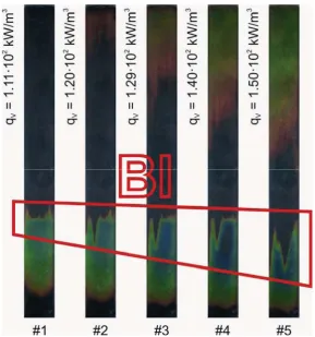
ESULTSBoiling incipience is recognised as a sudden drop in the heating surface temperature that follows its systematic increase, at constant capacity of the internal heat source. It is called “boiling front” and it shifts in the direction opposite to the liquid flow in the minichannel with the increase in the heat flux supplied to the heating surface [5,9-13]. Figure 6 shows hue distribution on the foil surface during increasing heat flux, obtained with liquid crystal thermography, with a visible “boiling front” (BI). The “boiling front” occurrence for the investigated enhanced heating foil was analysed in [9] of this collection of conference papers.
Figure 6: Images of temperature distribution on the heating wall during increasing heat flux, experimental parameters: u=0.14 m/s, G =240 kg/(m2s),
Approximate values of the heat transfer coefficient were obtained from the solution of the inverse heat conduction problem by means of MES combined with the Trefftz functions.
In the domains G
:
and F:
, a rectangular mesh, parallel to the coordinate system axes, has been introduced. The domainG
:
has been divided into 350 rectangular elements,F
:
- into from 39 to 75 rectangular elements. In each element j G:
,:
Fj sets of fournodes were placed in the vertices of the rectangular element.
Three parameters are connected with each node (function value at this node point; value of derivative with respect to x, value of derivative with respect to y), therefore 12
T-functions are used for approximation of temperature in an element:
120
12
24
,
24
4
24
,
6
6
,
2
6
,
6
2
,
2
2
,
,
,
,
1
x
y
x
y
x
2y
2x
2y
y
3x
3xy
2x
3y
xy
3x
4x
2y
2y
4x
4y
x
2y
3y
5 .120
36
120
,
24
12
120
5 3 3 5 4 2 3 5
xy
y
x
y
x
xy
y
x
x
. In the whole domain
G
:
702 nodes have beenplaced, in the domain
F
:
- from 80 to 152 nodes. The function,
0
,
5
1 2y
q
y
x
u
V F
O
has been assumed to be the particular solution of Eq. (2).
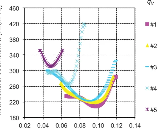
Local heat transfer coefficients as a function of the distance from the inlet to the minichannel have been presented in Fig. 7.
180 220 260 300 340 380 420 460
0.02 0.04 0.06 0.08 0.10 0.12 0.14
he
at
t
ran
sf
er
c
o
e
ff
ic
ie
nt
D
[W/(
m
2
K)]
distance from the inlet x [m]
#1
#2
#3
#4
#5
q
VFigure 7: Heat transfer coefficient dependence on the distance along the minichannel length, parameters as for Fig. 6
6. C
ONCLUSIONSThe determined approximates of the glass barrier and heating foil temperatures strictly satisfy the respective differential equations, whereas the boundary conditions are approximately satisfied.
In the minichannel flow boiling, considerable heat transfer enhancement takes place at boiling incipience. It is observed as a sharp increase in the heat transfer coefficient. Under subcooling boiling, local heat coefficients exhibit relatively low values.
A
CKNOWLEDGEMENTSThe research has been financially supported by the Polish Ministry of Science and Higher Education, Grant No. N N512 354037 for the years 2009-2012.
R
EFERENCES1. Alifanow O.M., Inverse heat transfer problems, Springer-Verlag, Berlin, 1994. 2. Cialkowski M. J., Frackowiak A., Solution of a stationary 2D inverse heat
conduction problem by Trefftz method, J. Therm. Sc. 11 (2002),pp. 148-162. 3. Cialkowski M. J., New Type of basic functions of FEM in application to solution of
inverse heat conduction problem, J. Therm. Sc. 11 (2002), pp. 163-171.
4. Herrera I., Trefftz method: A general theory, Numer. Methods Partial. Diff. Eq. 16 (2000), pp. 561- 580.
5. Hozejowska S., Piasecka M., Poniewski M. E.: Boiling heat transfer in vertical minichannels. Liquid crystal experiments and numerical investigations, Int. J. of Thermal Sciences, 48, No. 6 (2009), pp. 1049-1059.
6. Kita E., Trefftz method: an overview, Adv. Eng. Software 24 (1995), pp. 3-12. 7. Kurpisz K., Nowak A. J., Inverse thermal problems, Int. Series on Comput.
Mechanics Publications, Southampton, UK and Boston, USA, 1995.
8. Ozisik M. N., Orlande H. R. B., Inverse heat transfer: fundamentals and applications, Taylor & Francis, New York, 2000.
9. Piasecka M.: Investigation into flow boiling heat transfer in a minichannel with enhanced heating surface. Ibid.
10. Piasecka M., Hozejowska S., Poniewski M. E.: Experimental evaluation of flow boiling incipience of subcooled fluid in a narrow channel, Int. J. of Heat and Fluid Flow 25 (2004), pp. 159-172.
11. Piasecka M., Maciejewska B.: Experimental investigation on flow boiling heat transfer in minichannels of different spatial orientations, Proc. of the Int. Conf. Experimental Fluid Mechanics 2010, 24-26 XI.2010, Liberec, vol. 2, pp. 524-533. 12. Piasecka M., Poniewski M. E.: Hysteresis phenomena at the onset of subcooled
nucleate flow boiling in microchannels, Heat Transfer Eng. 25 (2004), pp. 44-51. 13. Piasecka M.: Experimental investigation on flow boiling heat transfer in
minichannels of different spatial orientations, Proc. of the Int. Conf. Experimental Fluid Mechanics 2009, 25-27 XI.2009, Liberec, pp. 290-303.
14. Trefftz E., Ein Gegenstück zum Ritzschen Verfahren, 2, Int. Kongress für Technische Mechanik, Zürich (1926), pp. 131-137.