Effect of Button Geometry on TRIP800 Steel
Resistance Spot Weldment
Hayriye Ertek Emre 1, Ramazan Kaçar 2
Research Asistant, Department of Manufacturing Engineering, Karabük University, Karabük, Turkey1
Professor, Department of Manufacturing Engineering, Karabük University, Karabük, Turkey2
ABSTRACT: TRIP steels which are used for automotive industry are usually welded by resistance spot welding. The welding current, welding time and electrode force are most important welding parameters which affect to properties of the resistance spot welded steels. In this study, the TRIP800 steels were joined with a constant electrode force and welding time by using various welding currents. An effect of welding current on the joint strength and weld button geometry; nugget diameter, nugget height and electrode indentation depth was investigated. It was found that the heat input related to the increasing welding current notably affects weld button geometry and mechanical properties. It was determined that the strength of the weldment increased up to critical button geometry later on it fall down. In addition, cross tensile test was also applied to the samples which were obtained by using optimum welding parameters. The fracture modes of test samples were evaluated and hardness measurements were also determined.
KEYWORDS:TRIP800 steels, Resistance spot welding, Welding current, Button geometry.
I. INTRODUCTION
Steel sheets used in the automotive industry are classified and identified according to their metallurgic design and strength [1-3]. According to classification by strength, the tensile strength of “Ultra-High Strength Steels” (UHSS) is above 700 MPa [4,5]. Car manufacturers have indicated that the TRIP steel (in UHSS steel groups) has the highest potential of reducing the weight of a car and absorbing sudden impacts within itself [6-8].
Among the welding methods used in the automotive industry, resistance spot welding has a significant position particularly in robotic applications. There are different studies conducted on resistance spot welding of TRIP steels [9-14]. In one of these studies, Khan et al. detected undissolved ferrite and martensite in the weld nugget of TRIP780 steels, as well as a small amount of untransformed retained austenite phases in the heat affected zone (HAZ) of such steels. They reported that in comparison to conventional steels, the strength of joints made with these steels is much higher and that failure occurs in the pullout mode [15]. The weldability of other steels with TRIP steels were compared by Shi and Westgate [16]. The researchers emphasized that a higher electrode pressure force was required to be applied during welding processes due to the fact that TRIP steels contain more carbon [16]. Kim et al., on the other hand, reported that welding of galvanized TRIP steels required a higher welding current and longer welding time due to having less weldability in comparison to ungalvanized steels [17]. It was also reported that the increase of hardness which occurred in the weld nugget of the TRIP700 steel was lowered while the brittleness in the area was reduced to a certain extent [18]. In another study, Long et al. carried out fatigue and damage analyses in resistance welded connections of the DP600, TRIP600 and HSLA340YGI steels used in automotive industry and it was stated that the cracks formed under both low and excessive loading conditions progressed vertically towards the joint interface [19]. A review of the literature on the subject revealed no detailed studies about the strength of TRIP steel weldments and the effect welding current has on the weld nugget geometry. Therefore, based on the welding current, nugget diameter, dn,
nugget cross section height, hn, nugget diameter/nugget height ratio, dn/hn, electrode indentation, ei, of the weld
II. EXPERIMENTALPROCEDURE
TRIP800 steel sheets in 1.5 mm thickness were used for experimental processes. The chemical composition of steel is given in Table 1. A timer and current controlled resistance spot welding machine having 60 kVA capacity and pneumatic application mechanisms with a single lever was used in experiments. The electrode force was continuously measured and controlled at fixed 6 kN force during the experiments. The welding time, clamping and holding times were kept constant as 15 cycles in all series. The welding current was increased from 1 to 10 kA by increasing 1kA.
Spherical tip electrodes (CuCrZr) having 5.5 mm sphere diameter were used in the experiments. The parameter used for joining of the spot weld samples is shown in Table 2. (1 cycle period means 0.02 second).
Table. 1 Chemical composition of TRIP 800 steel (% wt).
Material C Si Mn P S Cr Mo Al Fe
TRIP800 0,2 1,66 1,69 0,015 0,0002 0,006 0,01 0,43 Bal.
Table. 2 Welding parameters.
Welding current (kA)
Electrode force (kN)
Welding time (cycle)
Hold time (cycle)
Squeeze time (cycle)
Clamping time(cycle)
1-10 6 15 15 25 15
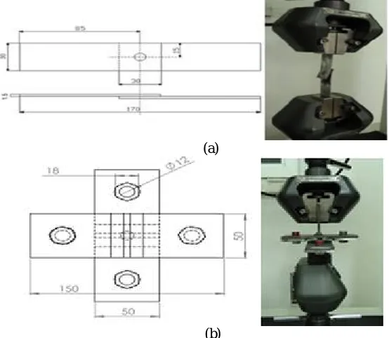
Welded samples were exposed to tensile shear test for determining joint strength while the cross tensile tests were also applied for samples that generated maximum tensile shear strength. The tensile shear and cross tensile sample assemblies are shown in Fig. 1 (a) and (b). Five test samples were prepared and tested for each parameters by using Shimadzu testing machine at a cross head of 5 mm/min.
(a)
(b)
The failure modes were evaluated from the tested samples by using Zeiss Ultra Plus type SEM microscope. The weld nugget geometry; dn, hn, and ei, were measured on the cross section sample (Fig 2). In addition hn/dn ratio was
calculated and its effect on the mechanical properties was determined. The samples were etched for 5 s with 2 % nital. Hardness measurements were carried out from base metal to the weld nugget by using a Shimadzu micro hardness tester by using 500 g load (Fig 2).
Fig. 2. Microhardness measurements and weld geometry profile.
III.RESULTSANDDISCUSSIONS
It is known that the strength of weldment is substantially affected by the nugget geometry, hn, dn and ei which depend
on welding parameters. [20,21]. The dn and hn changes are not the sole factors that influence strength. It is known that
the heat input and electrode indentation increase which are affected by welding parameters influence the hn/dn ratio and
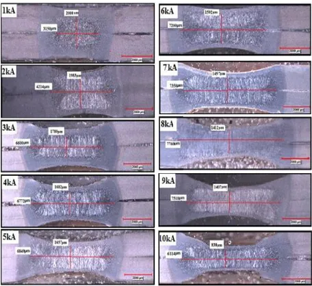
thus, the strength [20]. Therefore, the hn, dn and ei of the weldment were measured over the macrograph which was
taken from the cross section of the weld joint and demonstrated in Figure 3.
Fig. 3 Themacrostructure of welded sample which joined with different welding current.
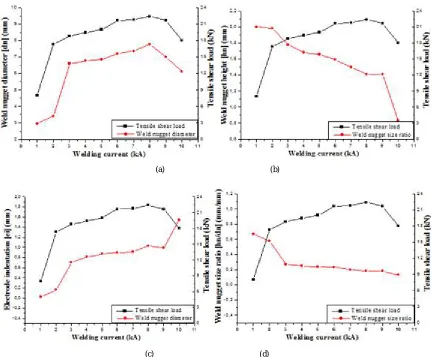
Fig. 4 The relationship of (a) weld nugget diameter, (b) weld nugget height, (c) electrode indentation, (d) nugget size ratio between welding current and tensile shear load.
As seen in Fig. 4 (a), a noticeable growth is seen in nugget diameter due to the heat input increase in parallel with welding current increases up to 8 kA; on the other hand, welding current higher than 8 kA caused the nugget diameter to shrink due to expulsion. Similarly, it was reported that the nugget diameter which grows as heat input increases contracts due to expulsion and spurting over a certain value [22-25]. The growth of the nugget size improved the strength of the joint (Fig. 4 (a)). Wan et al. and Kong et al. [26, 27] reported that increasing welding current positively affect the strength of joints. It was also reported that the heat input which increases in parallel with the rise in welding current extends the size of the fusion zone, which in turn enhances strength [28-30]. Vural and Akkuş [31] stated that an increase in the welding current up to a critical value leads to a rise in dn, which causes the strength to increase at
first; however they also stated that after the critical welding current value is exceeded, the dn and the strength is
decreased due to expulsion. In another study, it is reported that the nugget diameter grows and flattens as welding current and welding time increases, which in return causes the strength to rise; it is also reported that after a certain degree of flattening, penetration is reduced and the strength decreases [28-33].
(a) (b)
As can be seen in Figure 4 (b) and (c), the increasing welding current caused the ei to rise and hn to decrease
noticeably. The strength decreased in parallel with a decline in hn section. The fact that ei increases while hn decreases
excessively in samples connected with welding current over 8 kA indicates that the heat input for TRIP800 steel is very high. As can be seen in Figure 4 (b), the nugget section thickness varied between 1.4 and 1.6 mm at the welding current range of 6-8 kA where optimum strength is acquired and a considerable decrease was detected in the nugget hn value of
samples connected with welding current over 8 kA as the ei increased. Figure 4 (c) indicates that maximum strength
was acquired within a welding current range of 6-8 kA and an ei range of 0.9-1 mm, and shows that the desired dn
cannot be achieved under the aforementioned ei value while going over this value once again leads to inability to
achieve the desired strength due to excessive fusion and spurting. Figure 4 (d) demonstrates that as the hn/dn ratio
decreases in parallel with welding current increases, the acceptable value of strength is obtained at the welding current range of 6-8 kA while the range of the hn/dn ratio is 0.15-022 and that the preferred amount of strength cannot be
acquired under or over this range.
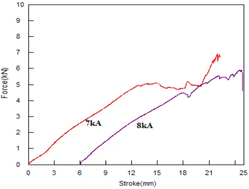
A cross tensile test was applied to weldments at parameters which the maximum tensile shearing strength value is achieved and the results are shown in Figure 5.
Fig. 5 Cross tensile test graphics.
As can be seen in Figure 5, the cross tensile strength values of samples joined with welding current of 7 and 8 kA were determined respectively as 5.1 kN and 5.9 kN. The increase in welding current led to a rise in the cross tensile strengths of weldments, in parallel with the tensile shear test. The test resulted in pullout failure mode in the HAZ. Pullout failure indicates that the weldment will have sufficient strength when forced to split with a static force. The correctness of the optimum welding parameters determined through the tensile shear test are thus confirmed by the cross tensile test. SEM images acquired from the fracture surfaces formed after the test are shown in Figure 6.
Fig. 6 Fracture surface acquired after the cross tensile test, (a) macro view, (b),(d) weld nugget-HAZ interface, (c) weld nugget.
The hardness distributions of the samples resistance spot welded with different welding current are graphically shown in Figure 7.
As can be seen in Figure 7, the hardness increases considerably in the HAZ and the weld nugget, compared to the base metal. While the base metal hardness value is 255 HV0.5, nugget hardness value varies between 540 and 550 HV0.5.
The high hardness can be associated with the transformation into martensite phases due to rapid heating and cooling during the welding process.
Fig. 7 Hardness profile of the weldment.
(a) (b)
It was detected that an increase in welding current, which can also be expressed as an increase in heat input, leads to a small change in the nugget and HAZ hardness, depending on the volume of the martensite phase formed in the structure. It is reported in similar studies that the hardness values of weld nugget vary between 400 and 550 HV0.5,
depending on the carbon content of TRIP steels [34-35].
IV. CONCLUSIONS
The findings acquired in the study are summarized below:
The dn and ei increased as the welding current increased up to 8 kA, which led to a rise in tensile shear strengths of
weldments. However the dn and strength of weldments made with welding current over 8 kA decreased due to
expulsion as the ei continued to increase.
As electrode indentation, ei increased and hn became thinner, the hn/dn ratio decreased. Since a smaller value of dn
was acquired due to insufficient heat input with lower welding current, the strength in weldments made with these was too low.
The desired and accepted strength is acquired with a welding current of 6-8 kA, hn of 1.4-1.6 mm, ei of 0.9-1 mm
and hn/dn ratio of 0.15-0.22. Since the desired dn cannot be achieved below these ranges and expulsion occurs
above these, the strength that is obtained is insufficient.
The cross tensile strength resulted in pullout failure in the HAZ around the nugget. While the fracturing was brittle in the weld nugget, it was semi-dendritic and semi-brittle in the weld nugget HAZ interface, associated with the structural transformation.
In comparison to the base metal, the hardness increased considerably in the HAZ and the weld nugget. The high value of hardness in the weld nugget can be associated with the transformation into martensite phases due to rapid heating and cooling during the welding process.
V. ACKNOWLEDGEMENT
This study was supported by Karabük University, Project Office. The authors would like to thank for their kind supports.
REFERENCES
[1] S. Sharifimehr, A. Fatemi, S.C. Cha, M.K. Bae and S.H. Hong, “Fatigue behavior of AHSS lap shear and butt arc welds including the effect of periodic overloads and underloads”, International Journal of Fatigue, vol.87, pp. 6–14, 2016.
[2] M. Shome and M. Tumuluru, “Introduction to welding and joining of advanced high-strength steels (AHSS)”, Welding and Joining of Advanced High Strength Steels (AHSS), pp. 1-8, 2015.
[3] A. Grajcar, R. Kuziak and W Zalecki, “Third generation of AHSS with increased fraction of retained austenite for the automotive industry”, Archives of Civil and Mechanical Engineering, vol. 12, no. 3, pp. 334–341, 2012.
[4] M.I. Latypova, S. Shin, B.C.D. Cooman and H.S. Kim, “Micromechanical finite element analysis of strain partitioning in multiphase medium manganese TWIP+TRIP steel”, Acta Materialia, vol. 108, pp. 219–228, 2016.
[5] G. Azizi, H. Mirzadeh and M.H. Parsa, “The effect of primary thermo-mechanical treatment on TRIP steel microstructure and mechanical properties”, Materials Science and Engineering: A, vol. 639, pp. 402–406, 2015.
[6] H.K. Zeytin, G. Güven and B. Berme, “Convetional and modern sheet metals”, International Iron & Steel Symposium, Karabuk, Turkey, pp. 434-447, 2012.
[7] K. Ushioda, “Recent developments in steel sheets”, Scandinavian Journal of Metallurgy, vol. 28, pp. 33-39, 1999.
[8] W.J. Dan, S.H. Li, W.G. Zhang and Z.Q. Lin, “The effect of strain-induced martensitic transformation on mechanical properties of TRIP steel”, Materials and Design, vol. 29, no. 4, pp. 604-612, 2008.
[9] Z. Yinghui, M. Yonli, K. Yonglin and Y. Hao, “Mechanical properties and microstructure of TRIP steels produced using TSCR process”, Journal of University of Science and Technology, Beijing, vol. 13, no. 5, pp. 416-421, 2006.
[10] D. Wu, L. Zhuang and L. Hui-sheng, “Effect of controlled cooling after hot rolling on mechanical properties of hot rolled TRIP steel”, Journal of Iron and Steel Research International, vol. 15, no. 2, pp. 65-70, 2008.
[11] S. Koh-Ichİ, M. Toshiki, H. Shun-Ichi and M. Yoichi, “Formability of Nb bearing ultra high strength TRIP-aided sheet steels”, Journal of Materials Processing Technology, vol. 177, no. 1, pp. 390–395, 2006.
[12] L. Skoalova, R.. Divišová and D. Jandová, “Thermo-mechanical processing of low-alloy TRIP steel”, Journal of Materials Processing Technology, vol. 175, no. 1, pp. 387–392, 2006.
[14] L. Zhuang, W. Di and H. Rong, “Austempering of hot rolled Si-Mn TRIP steels”, Journal of Iron and Steel Research International, vol. 13, no. 5, pp. 41-46, 2006.
[15] M.I. Khan, M.L Kuntz, E. Biro and Y. Zhou, “Microstructure and mechanical properties of resistance spot welded advanced high strength steels”, Materials Transactions,vol. 49, no. 7, pp. 1629 -1637, 2008.
[16] G. Shi and S.A.Westgate, “Resistance spot welding of high strength steels”, Eleventh International Conference on the Joining of Materials, Helsingor, Denmark, 2003.
[17] T. Kim, H. Park and S. Rhee, “Optimization of welding parameters for resistance spot welding of TRIP steel with response surface methodology”, International Journal of Production, vol. 43, no. 21, pp. 4643–4657, 2005.
[18] G. Shi and S.A. Westgate, “Techniques for improving the weldability of trip steel using resistance spot welding”, 1st International Conference Super-High Strength Steels, Rome, Italy, 2005.
[19] X. Long and S.K. Khanna, “Fatigue properties and failure characterization of spot welded high strength steel sheet”, International Journal of Fatigue, vol. 29, pp. 879–886, 2007.
[20] S. Aslanlar, “The effect of nucleus size on mechanical properties in electrical resistance spot welding of sheets used in automotive industry”, Materials& Design,vol. 27, pp. 125–131, 2006.
[21] X.Q. Zhang, G.L. Chen and Y.S. Zhang, “Characteristics of electrode wear in resistance spot welding dual-phase steels”, Materials & Design, vol. 29, no. 1, pp. 279–283,2008.
[22] B. Kocabekir, R. Kaçar, S. Gündüz and F. Hayat, “An effect of heat input, weld atmosphere and weld cooling conditions on the resistance spot weldability of 316L austenitic stainless steel”, Journal of Materials Processing Technology, vol. 195, pp. 327–335, 2008.
[23] I. Sevim, F. Hayat and M.K. Kulekci, “Nucleus geometry and mechanical properties of resistance spot welded coated–uncoated DP automotive steels”, Bull. Mater. Sci., vol. 36, no. 6, pp. 1049–1055, 2013.
[24] F. Hayat, B. Demir, M. Acarer and S. Aslanlar, “Effect of weld time and weld current on the mechanical properties of resistance spot welded IF (DIN EN 10130–1999) steel”, Kovove Materials, vol. 47, no. 1, pp. 11-17, 2009.
[25] I.S. Hwang, M.J. Kang and D.C. Kim, “Expulsion reduction in resistance spot welding by controlling of welding current waveform”, 11th International Conference on the Mechanical Behavior of Materials, vol. 10, pp. 2775–2781, 2011.
[26] X. Wan, Y. Wang and P. Zhang, “Modelling the effect of welding current on resistance spot welding of DP600 steel”,Journal of Materials Processing Technology, vol. 214, no. 11, pp. 2723–2729, 2014.
[27] J.P. Kong, T.K. Han, K.G. Chin, B.G. Park and C.Y. Kang, “Effect of boron content and welding current on the mechanical properties of electrical resistance spot welds in complex-phase steels”,Materials & Design, vol. 54, pp. 598–609, 2014.
[28] P. Marashi, M. Pouranvari, S. Amirabdollah, A. Abedi and M. Goodarzi, “Microstructure and failure behavior of dissimilar resistance spot welds between low carbon galvanized and austenitic stainless steels”, Materials Science and Engineering A, vol. 480, pp. 175-180, 2008. [29] S. Fukuomuto, K. Fujiwara, S. Toji and A. Yamamoto, “Small-Scale resistance spot welding of austenitic stainless steels”, Materials Science
and Engineering A, vol. 492, no. 1-2, pp. 243-249, 2008.
[30] D. Özyürek, “An effect of weld current and weld atmosphere on the resistance spot weldability of 304L austenitic stainless steel”, Materials and Design, vol. 29, pp. 597-603, 2008.
[31] M. Vural and A. Akkuş, “On the resistance spot weldability of galvanized interstitial free steel sheets with austenitic stainless steel sheet”, Journal of Materials Processing Technology, vol. 1, no. 6, pp. 153-154, 2004.
[32] N. Ma and H. Murakawa, “Numerical and experimental study on nugget formation in resistance spot welding for three pieces of high strength steel sheets”, Journal of Materials Processing Technology, vol. 210, no. 14, pp. 2045–2052, 2010.
[33] M. Vural, A. Akkuş and B. Eryürek, “Effect of welding nugget diameter on the fatigue strength of the resistance spot welded joints of different steel sheets”, Journal of Materials Processing Technology, vol. 176, no.1–3, pp. 127–132, 2006.
[34] L. Cretteur, A.I. Koruk, L. Tosal-Martinez, “Improvement of weldability of TRIP steels by use of in-situ pre- and post-heat treatments”, Steel Res., vol. 73, pp. 314–319, 2002.