Multiplay Service Deployment Using
GEPON Technology
Karthikeyan.G.M1 , Karthick.K.K2 , Karthik.R3 , Ponnuvel.P4, Dr.S.Sumathi5
U.G. Students, Department of ECE, Adhiyamaan College of Engineering , Hosur, Tamilnadu, India1,2,3,4
Professor and Head , Department of ECE, Adhiyamaan College of Engineering, Hosur, Tamilnadu, India5
ABSTRACT: This network provides two-way operation in which traffic from an optical line terminal (OLT) is sent to/from multiple optical network units (ONUs). Namely, OLT-ONU traffic is called “downstream” (point- to-multipoint) and meanwhile, reverses ONU-OLT direction traffic is called “upstream” (multipoint-to point). After a presentation of the France Telecom Group's optical deployment project based on available technology, our interest for the Next Generation Passive Optical Network is described. With the need for increased bit rate, splitting ratio, as well as the reach extension, more optical budget will be required. Solutions for optical amplification in the target architectures which can ensure the evolution of the access network are presented. These solutions are compared in different schemes and the budget increase for the upgrade of Gigabit PON (GPON) system is deduced.
KEYWORDS: Multiplay Services Video, Data, Voice in single fibre cable.
I . INTRODUCTION
Crucial feature of any communication network is its survivability which refers to the ability to withstand component failures and to continue providing services in disruption conditions. Providing resilience against failures is therefore an important requirement for many high-speed networks. As these networks carry more and more data, the amount of disruption caused by a network fault or attack becomes more and more significant. Today, majority of broadband connectivity is offered through Digital Subscriber Line (DSL), Cable Modem and to the limited extent with Wireless technology.
FTTH provides enormous bandwidth and long reach offering multi-play services (Data, Voice,Video etc.) on a single fiber. FTTH is future proof solution for providing add-on services such as Video on demand, Online Gaming, HDTV etc.FTTH network based on Gigabit Ethernet Passive Optical Network(GEPON) technology.
II.RELATED WORK
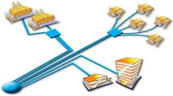
the passive optical splitters in the access node. Fiber saving between splitter and CO/POPrelevant in scenarios where existing cables or ducts need to be reused towards the splitter, or where fiber deployment is restricted (e.g., aerial cabling)Less relevant for Greenfield scenarios (marginal cost of fiber compared to digging, splicing, ...).Analog video overlay for existing broadcast services emulates cable TV distribution plant on a separate downstream wavelengthdelaying introduction of IP TV requires equivalent of cable headend at each OLT side.Port saving in the CO/POPneed to terminate thousands of fibers on switch portsPON can reduce this by 1...2 orders of magnitude compared to P2Pport costs on a per-customer base, however, are roughly equivalent. No deployment of active equipment in the outside plant in Europe & ME typically loops are sufficiently short so that also for P2P there isno need to put active equipment into the outside plant,unless the fiber saving argument becomes relevant RF TV.
FIG 1: point-to-point network topology.
III.PON TECHNOLOGY (Passive Optical Networks)
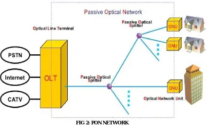
A PON is a fiber network that only uses fiber and passive components like splitters and combiners rather than active components like amplifiers, repeaters, or shaping circuits. Such networks cost significantly less than those using active components. The main disadvantage is a shorter range of coverage limited by signal strength. While an active optical network (AON) can cover a range to about 100 km (62 miles), a PON is typically limited to fiber cable runs of up to 20 km (12 miles). PONs also is called fiber to the home (FTTH) networks.The term FTTx is used to state how far a fiber run is. In FTTH, x is for home. You may also see it called FTTP or fiber to the premises. Another variation is FTTB for fiber to the building. These three versions define systems where the fiber runs all the way from the service provider to the customer. In other forms, the fiber is not run all the way to the customer. Instead, it is run to an interim node in the neighborhood. This is called FTTN for fiber to the node. Another variation is FTTC, or fiber to the curb. Here too the fiber does not run all the way to the home. FTTC and FTTN networks may use a customer’s unshielded twisted-pair (UTP) copper telephone line to extend the services at lower cost. For PON arrangement is a point to multi-point (P2MP) network where a central optical line terminal (OLT) at the service provider’s facility distributes TV or Internet service to as many as 16 to 128 example, a fast ADSL line carries the fiber data to the customer’s devices.
The typical customers per fiber line (see the figure). Optical splitters, passive optical devices that divide a single
computers, or a wireless router. The ONU/ONT may be one device.In the basic method of operation for downstream distribution on one wavelength of light from OLT to ONU/ONT, all customers receive the same data. The ONU recognizes data targeted at each user. For the upstream from ONU to OLT, a time division multiplex (TDM) technique is used where each user is assigned a timeslot on a different wavelength of light. With this arrangement, the splitters act as power combiners. The upstream transmissions, called burst-mode operations, occur at random as a user needs to send data. The system assigns a slot as needed. Because the TDM method involves multiple users on a single transmission, the upstream data rate is always slower than the downstream rate.
FIG 2: PON NETWORK
IV.GEPON
Over the years, various PON standards have been developed. In the late 1990s, the International Telecommunications Union (ITU) created the APON standard, which used the Asynchronous Transfer Mode (ATM) for long-haul packet transmission. Since ATM is no longer used, a newer version was created called the broadband PON, or BPON. Designated as ITU-T G.983, this standard provided for 622 Mbits/s downstream and 155 Mbits/s upstream.While BPON may still be used in some systems, most current networks use GPON, or Gigabit PON. The ITU-T standard is G.984. It delivers 2.488 Gbits/s downstream and 1.244 Gbits/s
upstream.GPON uses optical wavelength division multiplexing (WDM) so a single fiber can be used for both
downstream and upstream data. A laser on a wavelength (λ) of 1490 nm transmits downstream data. Upstream
of a single fiber is 1:32 or 1:64. That means each fiber can serve up to 32 or 64 subscribers. Split ratios up to 1:128 are possible in some systems.As for data format, the GPON packets can handle ATM packets directly. Recall that ATM packages everything in 53-byte packets with 48 for data and 5 for overhead. GPON also uses a
generic encapsulation method to carry other protocols. It can encapsulate Ethernet, IP, TCP, UDP, T1/E1, video, VoIP, or other protocols as called for by the data transmission. Minimum packet size is 53 bytes, and the maximum is 1518. AES encryption is used downstream only.The latest version of GPON is a 10-Gigabit version called XGPON, or 10G-PON. As the demand for video and over the top (OTT) TV services has increased, there is an increasing need to boost line rates to handle the massive data of high-definition video. XGPON serves this purpose. The ITU standard is G.987.XGPON’s maximum rate is 10 Gbits/s (9.95328) downstream and 2.5 Gbits/s (2.48832) upstream. Different WDM wavelengths are used, 1577 nm downstream and 1270 nm upstream. This allows 10-Gbit/s service to coexist on the same fiber with standard GPON. Optical split is 1:128, and data formatting is the same as GPON. Maximum range is still 20 km. XGPON is not yet widely implemented but provides an excellent upgrade path for service providers and customers.
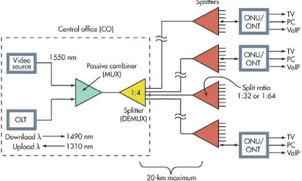
FIG 3: Most PONs are configured like this. The number of splitters and split levels varies with the vendor and the system. Split ratios are usually 1:32 or 1:64 but could be higher.
well as downstream. A variation uses 10 Gbits/s downstream and 1 Gbit/s upstream. The 10-Gbit/s versions use different optical wavelengths on the fiber, 1575 to 1580 nm downstream and 1260 to 1280 nm upstream so the 10-Gbit/s system can be wavelength multiplexed on the same fiber as a standard 1-Gbit/s system.
V.SPLITTER TECHNOLOGY
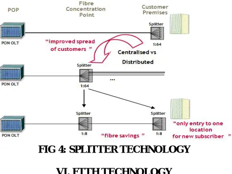
Gigabit Ethernet Passive Optical Network (PON) splitters play an important role in Fiber to the Home (FTTH) networks by allowing a single PON network interface to be shared among many subscribers. The PLC Splitter contain no electronics and use no power. They are the network elements that put the passive in Passive Optical Network and are available in a variety of split ratios, including 1:8, 1:16, and 1:32.Splitters are installed in each optical network between the PON Optical Line Termination (OLT) and the Optical Network Unit(ONU) that the OLT serves. Networks implementing BPON, GPON, EPON, 10G EPON, and 10G GPON technologies all use these simple optical splitters. In place of an optical splitter, a WDM PON network will use an Arrayed Wave Guide (AWG).A PON network may be designed with a single optical splitter, or it can have two or more splitters cascaded together. Since each optical connection adds attenuation, a single splitter is superior to multiple cascaded splitters. One net additional coupling (and source of attenuation) is introduced in connecting two splitters together.A single splitter is shown in the GPON network diagram below. Note that the splitter can be deployed in the Central Office (CO) alongside the OLT, or it may be deployed in an Out Side Plant (OSP) cabinet closer to the subscribers. A splitter can also be deployed in the basement of a building for a Multiple Dwelling Unit (MDU) installation (not shown).An interesting (and strange) fact is that attenuation of light through an optical splitter is symmetrical. It is identical in both directions. Whether a splitter is combining light in the upstream direction or dividing light in the downstream direction, it still introduces the same attenuation to an optical input signal (a little more than 3 dB for each 1:2 split).There are two basic technologies for building passive optical network splitters: Fused Biconical Taper (FBT) and Planar Light wave Circuit(PLC). Fused Biconical Taper is the older technology and generally introduces more loss than the newer PLC splitters, though both PLC and FBT splitters are used in PON networks.A Fused Biconical Taper (FBT) splitter is made by wrapping two fiber cores together, putting tension on the optical fibers, and then heating the junction until the two fibers are tapered from the tension and fused together. FBT attenuation tends to be a bit higher than attenuation from PLC splitters.A splitter is diagrammed in the figure below. A PLC splitter is made with techniques much like those to manufacture semiconductors, and these optical splitters are very compact, efficient, and reliable. A single 1:32 PLC splitter may be no larger than 1 cm x 2 cm.
FIG 4: SPLITTER TECHNOLOGY
VI. FTTH TECHNOLOGY
Fiber to the home (FTTH) – Each device at the subscriber premise is connected by a dedicated fibre to a port on the equipment in the POP, or to the passive optical splitter, using shared feeder fibre to the POP. It uses 100BASE-BX10 or 1000BASE-BX10 transmission for Ethernet connectivity, mainly GPON (or EPON) in case of point-to-multipoint connectivity.
Fiber to the building (FTTB) – each optical termination box in the building (typically in the basement) is connected by a dedicated fibre to a port on the equipment in the POP, or the optical splitter, using shared feeder fibre to the POP. The connections between subscribers and the building switch can be fibre or copper based and use some form of Ethernet transport suited to the medium available in the vertical cabling. In some cases building switches are not individually connected to the POP but are interconnected in a chain or ring structure in order to utilize existing fibres deployed in particular topologies and to save fibres and ports in the POP. The particular case of bringing fibre directly into Central Office/POP Access Loop Customer Premise Fibre To The Central Office Fibre To The
the apartment from POP or optical splitter onwards, without any switch in the building, brings us back to the fibre-to-the-home scenario.
Fibre to the curb (FTTC) – each switch / DSLAM, typically in a street cabinet, is connected to the POP via a single fibre or a pair of fibres, carrying the aggregated traffic of the neighbourhood via Gigabit Ethernet or 10 Gigabit Ethernet. The connections between subscribers and the switch in the street cabinet can be fibre or copper based, and use either100BASE-BX10, 1000BASE-BX10, or VDSL2. This architecture sometimes is also called “Active Ethernet” as it requires active network elements in the field.
This document will however concentrate on FTTH/B deployments because in the long term they are considered the target architecture due to their virtually unlimited scalability.
The two most widely used topologies are point-to-multipoint, which is often combined with a passive optical network (PON) architecture, and point-to-point, typically using Ethernet transmission technologies. Point-to-multipoint topologies with passive optical splitters in the field are deployed in order to be operated by one of the standardized PON technologies (GPON is today’s frontrunner in Europe, while EPON has been massively deployed in Asia) using time-sharing protocols to control the access of multiple subscribers to the shared feeder fibre. Active Ethernet technology can also be used to control subscriber access in a point-to-multipoint topology – this requires placing Ethernet switches in the field.
VII.CONCLUSION
it is a point to multipoint services, it can send and receive the data into a single fibre. A single fibre is enough to transmit and receive all the three signals i.e voice, video, data. The ITU-T standard is G.984. It delivers 2.488 Gbits/s downstream and 1.244 G bits/s upstream.
REFERENCES
[1] J.M. Oh, S.G. Koo, D. Lee, S.J. Park: Enhanced system performance of an RSOA based hybrid WDM/TDM-PON system using a
remotely pumped erbium-doped fiber amplifier, Proc. OFC 2007, Anaheim.
[2] G. Talli, C.W. Chow, E.K. MacHale, P.D. Townsend : High split ratio 116 km reach hybrid DWDMTDM 10 Gb/s PON employing
R-ONUs, Proc. ECOC 2006 Cannes.
[3] G. Della Valle, G. Sorbello, A. Festa, S. Taccheo, K. Ensser : High-gain erbium-doped waveguide amplifier for bidirectional operation,
Proc. ECOC 2006 Cannes.