Optimization of Bumper Column of a Low
Speed Vehicle
Sagar H N 1, Pavana Kumara B A2, Manjunath Siddappa Bailwad3, Punith H4 Bharath HB5
Assistant Professor, Department of Mechanical Engineering, Sri Krishna Institute of Technology, Bangalore, India1
U.G. Student, Department of Mechanical Engineering, PNS Institute of Technology, Bangalore, India2,3,4,5
ABSTRACT: Bumper beam column is a structural component is placed between the bumper and the enginemounts. During the crash events the bumper beam get deformed itself and not transfer any amount of energy to the next element because of this the engine and other element next to the bumper Beam or totally safe. The impact analysis of segmented bumper beam was conducted and getting a stress in the first segments of 522 Mpa and second segmented have 43.5 Mpa, But what we seen was in the first segment is totally failed because it exceeds the ultimate strength of mild steel so in order to reduce the stress in the first segment, we go for Optimization using tosca software for both the segment of bumper beam. In the Optimization we are varying the parameter of connection angle by an zero to 90degree, segmented height bearing ratio h1/h2 = 40 /60 and load of 55 km per hour has been applied on the column. After Optimization we are getting a stress value in first segments was 343.5 Mpa and in the second segment of 28.7 Mpa that shows the two segments are totally within the yield stress of mild steel so the element next to the bumper columns are totally safe.
KEYWORDS: solid works, Abaqus Explicit, Tosca.
I. INTRODUCTION
Bumper column are the latent wellbeing segments, because of impact it experiences twisting and it watches the effect vitality by the bumper beam itself. . Bumper beams are a thin walled structures set in halfway of car body and guard which is appeared beneath figure, which are utilized as vitality entrancing amid crash occasion. Bumper beam made substantial part from metal added substances. Beneath frontal crash mishaps, crash holder is relied upon to break down and itself spellbinding the crash quality. With the goal that harms to other casing in which components,lodge is limited. The formulation to calculate axial weigh down conduct of aluminum beam column in which proposed via Wierzbicki and Abramowicz. However the analytical guesses had been confirmed experimentally by means of Abramowicz and Jones, and Langseth and Hopperstad. Take a look at of segments beam column continues to be restrained; where this layout can possible to growth the perfect important load and unique substances in every section may be used. The crash field designs the usage of hybrid material of aluminum and metallic have been developed which will reduce crash box weight as much as 17.5%.
II. PROBLEM DEFINITION
The aim of this project is to study the stress induced in two segmented body on energy observing bumper beam and optimize the both segmented bumper beam in order to reduce the stress..Above configuration is optimized using TOSCA by using the parameters given below
Connection angle between segments (θ) will be of the range 0-45 degree of the interval of 5 degree each.
Connection length between segments (p) will be varied from 5-10mm of the interval 2.5 mm.
Outside diameter (do) will be varied from 100-200 of the interval 10mm each.
Segment Height and thickness ratio will be constant 40/60mm and 2/3mm respectively.
III. METHODOLOGY
The basic step is to create a geometric model of bumper beam is done using solid works modeling tool. Rigid mass is modeled and applied with a velocity equivalent to maximum speed specification. This is impacted on the bumper beam. Once the geometry is created as per specifications it is imported into hyper works for messing. The finite element model is prepared by meshing it with appropriate elements like linear hexahedral, contact elements and constraining the model by applying material properties and boundary conditions. This finite element model is imported to ABAQUS EXPLICIT to evaluating the explicit dynamic analysis and optimized the model by TOSCA software Results are analyzed and the impact damage is studied. The reaction forces are observed.
IV. GEOMETRIC MODELING
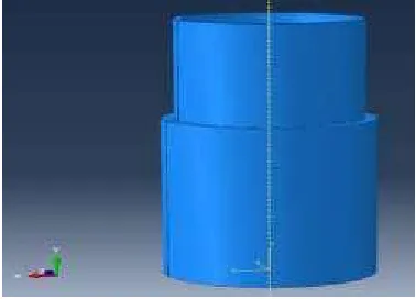
Figure shows the geometric model of a section of the bumper beam. The modeling has been done using SOLID works modeling software. The dimensions of bumper beam are considers from the literature survey. It consists of two
segment bumper beam which has the Connection angle between segments (θ) of 45 degree. Design parameters in two
segments bumper beam is as shown in figure.
V. MESHING
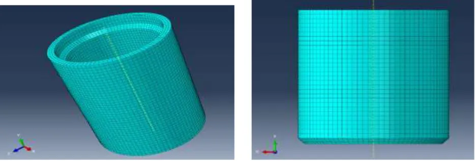
Figure: 3 Mesh models of two segments of crash box
Table No. 1 Elements and nodes count
TYPE OF ELEMENT linear hexahedral elements (C3D8R)
TOTAL NUMBER OF NODES 30684
TOTAL NUMBER OF ELEMENTS 23594
VI. LOADS AND BOUNDARY CONDITIONS
As shown in the fig, above the segmented bumper beam is places between the two rigid bodies at the top and bottom. The bottom rigid body is fixed completely which doesn't have any motion in any direction. The Boundary condition for the top rigid body will be free to move in Y axis and constrained to X and Z axis.
The velocity boundary condition is given to top rigid body in negative Y direction with the magnitude of 25m/s. The top rigid body acts as the impact load which will be of an object moving at 25m/s on the column. The analysis has been done in ABAQUS /CAE.
VII. RESULTS AND DISCUSSION
The above figures show the amount of stress in the segment box column. As the force applied from the top rigid body the first segment tends to deform. Maximum stress of 522Mpa is in the first segment and the minimum stress concentration is of 43.5Mpa in the second segment. The analysis shows the stress in the first segment doesn't intrude stress in the second segment.
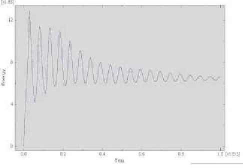
Figure 4: The plots shows the strain energy of the system
The above graph shows the history of the strain energy with respect to change in time when the load is applied on the system.
VIII. OPTIMISATION USING TOSCA
1. Displacement counter:
The above figures shows the total displacement in the segments when the load is applied. The total displacement is the mean of the initial position to final position of the segment. The maximum displacement in the negative Y direction is of 0.1mm which is red in color. The yellow color shows the displacement in the range of 0.1mm to 0.01mm. All the displacement is in the first segment. In the second segment there is very small displacement. Final Maximum displacement is 0.1 mm.
2. Stress counter:
IX. CONCLUSION
The maximum stress in the segment is found to be 522 Mpa which exceeded the ultimate strength of the
material to failure. After the optimisation, the stress reduced to ~344 Mpa.
The optimised stress is within ultimate limit which will just undergo plastic deformation and avoid
permanent failure.
Displacements are found to follow the expected buckling pattern in explicit dynamic analysis.
Total Energy is absorbed by the first segment crash box by affecting the rollup of the segment and doesn’t
intrude inside the second segment.
Total 70 % of both segment weight is reduced by this topology optimisation process.
REFERENCES
[1] “Crash Analysis of Car Cross Member Bumper Beam” by G.Yedukondalu Asst. Professor K L University Guntur t.-522502, India. Dr. A. Srinat UGC Research Awardee Professor Mechanical Engg., K L University Guntur Dt.-522502. Dr. J. Suresh Kumar Professor JNTUH University Hyderabad-500085, India.
[2] “Lumped Parameter Model for Design of Crash Energy Absorption Tubes” By Piyush Dube,M. L. J. Suman, Faculty of Engineering and Technology, M. S. Ramaiah University of Applied Sciences, Bangalore 560 054.