18th International Conference on Structural Mechanics in Reactor Technology (SMiRT 18) Beijing, China, August 7-12, 2005 SMiRT18- C05-1
IDENTIFICATION OF THE KEY PARAMETERS DEFINING THE LIFE
OF GRAPHITE CORE COMPONENTS
Mark N. Mitchell
Pebble bed Modular Reactor (Pty) ltd;
P.O.Box 9396
Centurion
0046
Republic of South Africa
Phone: +27 12 677 9400, Fax: +27 12 663 3053
E-mail:
[email protected]
ABSTRACT
The Core Structures of a Pebble Bed rector core comprise graphite reflectors constructed from blocks. These blocks are subject to high flux and temperatures as well as significant gradients in flux and temperature. This loading combined with the behaviour of graphite under irradiation gives rise to complex stress states within the reflector blocks. At some point, the stress state will reach a critical level and cracks will initiate within the blocks. The point of crack initiation is a useful point to define as the end of the part’s life.
The life of these graphite reflector parts in a pebble bed reactor (PBR) core determines the service life of the Core Structures. The replacement of the Core Structures’ components will be a costly and time consuming.
It is important that the components of the Core Structures be designed for the best life possible. As part of the conceptual design of the Pebble Bed Modular Reactor (PBMR), the assessment of the life of these components was examined.
To facilitate the understanding of the parameters that influence the design life of the PBMR, a study has been completed into the effect of various design parameters on the design life of a typical side reflector block. Parameters investigated include: block geometry, material property variations, and load variations.
The results of this study are to be presented.
Keywords: Graphite, PBMR, Probabilistic analysis, Life assessment.
1. INTRODUCTION
The core of a High Temperature Gas Cooled Reactor makes use of graphite as a moderator, reflector and as structural material. The reflection and structural functions of the graphite are often combined in the reflectors of the Core Structures of the HTR core.
The reflectors of the core structures of a typical Pebble Bed reactor consist of graphite blocks that, when assembled, perform both the reflection and structural functions. These parts are subject to both the high temperatures at which the core operates as well as high levels of fast neutron flux.
These irradiation induced effects lead to the build up of internal stress within a part, and while this build up of stress is lessened by an irradiation induced creep phenomenon, at some stage the internal stresses reach a level which results in the failure of the part. The time at which this point is reached is designated as the part’s lifetime. The methodology employed to predict the stress levels and assess the failure of a part is described later.
Owing to the uncertainties involved in the prediction of the lifetime of the individual parts, it is not possible to guarantee this lifetime. To mitigate the risk that the lifetime of the graphite parts of the Core Structures limits the lifetime of the plant, PBMR designs the parts to be replaceable, even though such a replacement may eventually prove unnecessary.
In a pebble bed reactor, refuelling takes place while the reactor is in operation and it is not possible to replace reflector parts during refuelling. It is, however, foreseen that these reflector parts can be replaced during a mid-life outage. This mid-life outage would take place at the end of the service life of the Core Structures.
The PBMR core is designed in such a way that the loss of integrity of some of the graphite parts will not result in the loss of the functional or structural integrity of the Core Structures; however, the loss of part integrity is one of the indicators that the service life of the core is approaching. Thus the lifetime of the individual parts relates directly to the service life of the core and to the time interval at which the mid-life outage will take place.
The replacement of the Core Structures’ components will be costly, specifically in terms of loss of plant availability.
It is thus imperative that the designer makes every effort to design the graphite parts for the longest life possible, thus reducing the likelihood that replacement will be required.
As part of the conceptual design of the PBMR, the assessment of the life of these parts was examined.
In addition to assessing the life of the parts for nominal conditions, a study was completed into the effect of various parameters (geometric, material and loading) on predicted life of the core. The aim of this study was to determine the key parameters that affect the life of the parts, identify possible changes that may allow for increase in the life of the parts, and to allow for an assessment of the robustness of the selected design. This study took the form of a series of single parameter and probabilistic studies into the effect of the input parameters on the life of a specific part of the side reflector of the PBMR core structures.
This paper reports on the study and its results, specifically the identification of the key parameters affecting the life of the graphite core components.
2. THE PEBBLE BED DESIGN
The design of the PBMR Core Structures is described briefly here as background information. Further information on the integrated PBMR plant design may be found in Koster et al. (2003) and on the design of the Core Structures in Mitchell’s (2004) presentation to the International Graphite Specialists Meeting.
The PBMR Core Structures consists of the Core Barrel Assembly (CBA) and the Core Structures Ceramics (CSC). The main components of the Core Structures are shown in
Figure 1
andFigure 2
.The CBA is a welded construction comprising three major components. These major components are the Core Barrel Support Structure (CBSS), the Core Barrel Sides and the Core Barrel Top Plate. The CBA is manufactured form 300 series austenitic stainless steel. The CBA provides for separation of the gases flowing within the core from the RPV and supports the CSC during normal operation and upset conditions.
Four major components comprise the CSC: The Bottom Reflector (BR), Side Reflector (SR), Top Reflector (TR), and the Centre Reflector (CR). The CSC is manufactured from individual graphite blocks. These blocks are arranged and interconnected so that they perform the required functions. The general arrangement and design principles that form the basis for the design of the CSC are based on the German designs for the THTR and later reactors.
Mechanical loads are borne by the CSC and transmitted to the CBA, which in turn transmits the loading to the RPV. These mechanical loads are a result of: dead weight, lateral loading due to the pebble bed, seismic loading, and the differential pressures established in the core.
The Bottom, Side and Top Reflectors fulfil the requirement for neutron reflection while protecting the metallic components from exposure to high neutron fluence levels. In addition, the primary coolant flow is channelled within the CSC. This protects the metallic components of the CBA and RPV from extreme temperatures. This coolant flow is introduced into the Bottom Reflector of the CSC. From there it is channelled to the top of the pebble bed in the Gas Riser Channels that are located in the Side Reflector. The gas then flows through the pebble bed from top to bottom, being heated in the process. At the bottom of the pebble bed, the gas is collected into the outlet plenum through flow slots between the blocks. The flow is then channelled from the outlet plenum into the outlet duct and out of the reactor.
The CSC provides the access channels for the Reactivity Control System (RCS) and Reserve Shutdown System (RSS) within the Side and Centre Reflector respectively.
Fuel Core
Control Rod Fuel Line
Side Reflector Centre Reflector Top Reflector
Bottom Reflector
SAS Extraction Point
SAS Channel
Fuel Core Reactor Pressure Vessel
Gas Riser Channels
Control Rod Channels
SAS Channels Core Barrel
Side Reflector
Centre Reflector Core Inlet Pipe connection
Core Outlet Pipe connection
Core Inlet Pipe connection
Figure 2: Horizontal cross section schematic of the PBMR Reactor unit.
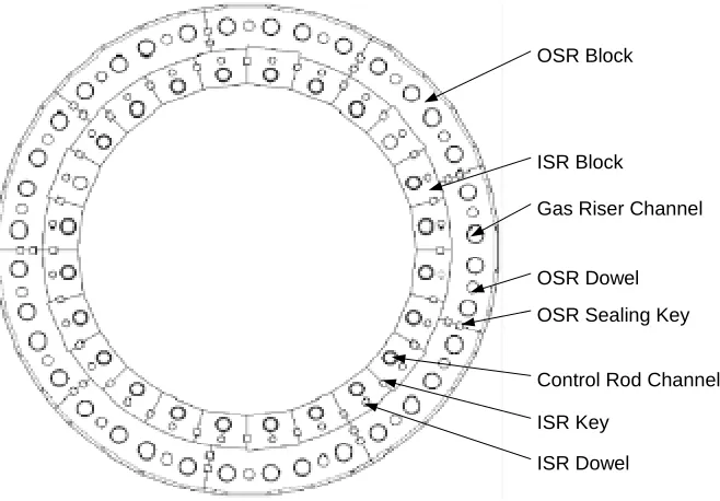
The study completed is focussed on a specific side reflector part. A detailed section view of the side reflector is shown in
Figure 3
.OSR Block
ISR Block
OSR Dowel Gas Riser Channel
OSR Sealing Key
Control Rod Channel
ISR Key
ISR Dowel
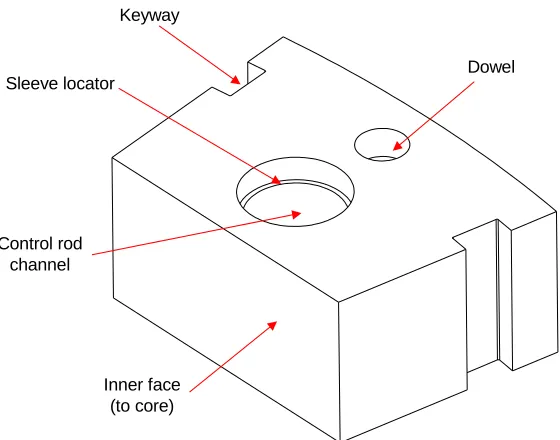
Keyway
Dowel
Control rod channel Sleeve locator
Inner face (to core)
Figure 4: A Typical Side Reflector Block
3. ASSESSMENT METHODOLOGY
Start
Define input parameters and
distibutions
Generate specific parameters for
this run
Gernate the input model
Complete Stress analysis
Complete Failure evaluation
Collate and post process the
results. Another Run?
End Yes
No
MATLAB
MSC.Mentat Using Python Scripts
MSC.Marc and GRMAT user defined models
MATLAB MATLAB
Figure 5: Flowchart describing the assessment process for the study.
More detail on each of the process steps is defined below.
3.1 Definition of Input parameters and distributions
A set of input parameters that was expected to be of interest was identified. These parameters include:
• Variation in the geometry of the part, representing design changes to the CSC that may be feasible should the study indicate suitable benefit,
• Variation in the irradiation behaviour of the material to account for uncertainties in this behaviour, and
• Variation in the loading of the parts, specifically in terms of the fast neutron flux and temperature fields.
For each identified parameter, the type of statistical distribution applied and the specific parameters required to define this distribution are identified. For the purposes of this study, only the uniform and normal distributions were applied to the input values.
A complete assessment of the variability of each input parameter was impossible as sufficient data was not available. In such cases, the variability of the input parameters was assumed. Such assumptions were based, where possible, on the previous experience with similar materials.
The full list of input parameters, their nominal values and their variability is described in
Table 4
(presented in the Appendix).
Specific details with respect to the treatment of the input parameters and their variations are dealt with below.
3.1.1 Part Geometry
A simplified model of the side reflector block was generated for the purpose of this analysis. The geometry of this part is defined by five key parameters, as indicated in
Figure 6
.Hole Posit
ion
Block Leng
th Hole Radius B
lo ck A
ng le
B
loc
k
H
e
ig
h
t
Figure 6: Simplified model of the Side reflector Block showing driving parameters.
3.1.2 Graphite Material Properties
Graphite exhibits material properties that vary significantly from batch-to-batch, Billet-to-billet (within a batch) and even within a single billet.
The following measured material properties values, for a single grade of graphite are provided:
Table 1: Some measure variability on graphite material properties
Property Unit Mean Value Standard Deviation
Std Dev as a percentage of
mean
Flexural Strength MPa 26.7 3.4 13 %
Coefficient of Thermal Expansion
10-6 m/m °C 4.45 0.061 1 %
While not all of the properties vary to the same extent, the values shown in the table are not unusual. For the purpose of the analysis, the general ratio of the standard deviation to the mean for the various properties was set to 10%. Exceptions were made for parameters that were expected to have larger ranges or for which there was larger uncertainty about the mean value.
Graphite, even the near isotropic grades designated for use in nuclear reactors, is a transversely anisotropic material. For the purpose of the study, the material properties in the various directions (parallel and perpendicular to the forming direction) were allowed to vary independently.
In general this approach is judged to conservatively estimate the level of variability within the material properties.
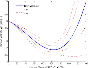
3.1.3 Graphite Irradiation Behaviour
When graphite is subject to damage by fast neutron irradiation, the following occurs:
a. The material experiences dimensional change, initially shrinking and later swelling. This dimensional change is not isotropic, but is transversely anisotropic as per the virgin material.
b. The elastic modulus of the material changes. The change in elastic modulus is coupled with a corresponding change in the materials strength.
c. The coefficient of thermal expansion (CTE) changes.
d. The thermal conductivity changes
e. The material is subject to creep under stress at significantly lower temperatures than graphite would creep at without irradiation.
There is significant uncertainty in determination of these irradiation effects for several reasons. Some of which are:
• Paucity of experimental data,
• Variability in the basic material,
• Variability in the irradiation conditions during the irradiation of specimens, and
• The need to use small specimens to reduce the cost of irradiating the material.
Figure 7: Dimensional change curve – showing the changes due to incorporation of the
variability.
3.1.4 Part Loading
Only the effect of the internal stresses was considered in the study. This is justifiable as the internal stresses at the end of the part’s life are generally an order of magnitude higher than the external stresses. To account for the internal stresses, the flux and temperature distribution within the part are considered in the analysis.
Both the flux and temperature distributions are represented as one-dimensional fields for simplicity. The variation of the flux and temperature fields is then incorporated as changes to the parameters that define these one-dimensional fields.
3.2 Generation Of Specific Parameters For A Run
Two separate approaches were followed in the completion of the study. The first was a sensitivity analysis, where each input parameter was individually varied over a predefined range. The second was a full probabilistic assessment, where all of the input parameters were varied randomly.
For the sensitivity analysis, two sets of parameters were generated: the first being a minimum value, the second a maximum value. For the normal distribution, the standard deviation values were added to or subtracted from the mean to arrive at the required minimum and maximum values.
After the specific input parameters were generated for each run, the next step was the generation of the finite element model and input data for the specific run.
3.3 Generate The Input Model
The input model for the specific run is generated. This was complicated by the decision to incorporate geometric changes into the model. A Python script was used to generate a finite element mesh of a part, with the required geometry, within MSC.Mentat.
3.4 Completion Of The Stress Analysis
The stress analysis of the graphite components was completed using the MSC.Marc Finite element package. This package was extended by means of a set of User Defined Subroutines, referred to a GRMAT, that were developed by PBMR. This code is similar, in many respects, to several previously described codes. For example, the VIENUS code developed by JAERI (Iyoku, T., Ishihara, M., and Shirai, H., 1991) or the code developed at INET (Yu, S. et al, 2004).
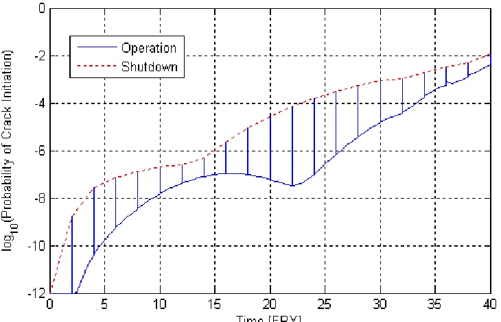
3.5 Completion Of The Failure Evaluation
The failure evaluation of the parts was completed in accordance with the methods presented in the draft KTA rule for the design of the Ceramic Internals of a High Temperature reactor (KTA, 1992) . This assessment is implemented in a similar manner to that described by Yu (2004). The lifetime of a part is measured at the point where it is predicted that the probability of crack initiation (also called the Failure Probability) reaches 10-2, as prescribed in the KTA rule.
The evolution of the probability of crack initiation, as a function of the operating time, during a typical run is shown in Figure 8. For this case, it can be observed that the life of the part is estimated as approximately 40 Full Power Years (FPY).
Figure 8: Evolution of the probability of crack initiation with operating life.
3.6 Collation And Post Processing Of Results
The results for each run were collated and post processed. The following results are of specific interest:
• The relative sensitivities of the predicted life to each component.
ii. For the probabilistic assessment:
• The mean predicted life and the distribution of the predicted lifetimes about this mean, and
• The correlation between the inputs and outputs to identify the inputs that have the most significant effect on the life prediction.
4. ASSESSMENT
The assessment of the results are described in this section.
4.1 Importance Of Parameters To The Life Assessment
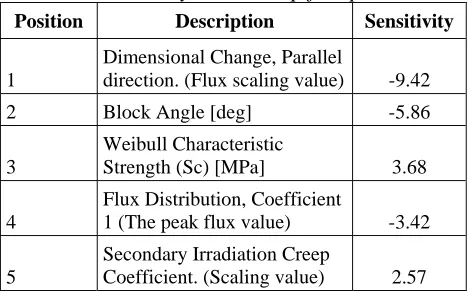
The importance of the parameters from the life assessment are derived from the sensitivity analysis. For each parameter, the magnitude in the change in predicted life is compared with the magnitude of the expected change in the variable. The five most sensitive parameters, as determined by this study, and their relative sensitivities are described in Table 2. The scaling parameter is essentially the gradient in change in life for the parameter and the sign of the sensitivity parameter indicates whether or not the life of the part will increase or decrease with an increasing value of the parameter.
Table 2: Sensitivity results, top five parameters
Position Description Sensitivity
1
Dimensional Change, Parallel
direction. (Flux scaling value) -9.42
2 Block Angle [deg] -5.86
3
Weibull Characteristic
Strength (Sc) [MPa] 3.68
4
Flux Distribution, Coefficient
1 (The peak flux value) -3.42
5
Secondary Irradiation Creep
Coefficient. (Scaling value) 2.57
Figure 9: Sensitivity result overlaid on the results of the probabilistic simulation for two of the
input parameters.
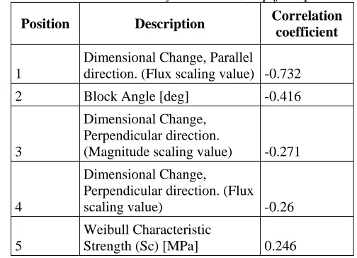
An alternative measure of the relative importance of the input parameters is to examine the correlation between the inputs and the desired output. The results of this correlation study are presented in Table 3. Only three of the top five parameters are common between the sensitivity study and the probabilistic study.
Table 3: Probabilistic analysis results, top five parameters
Position Description Correlation coefficient
1
Dimensional Change, Parallel
direction. (Flux scaling value) -0.732
2 Block Angle [deg] -0.416
3
Dimensional Change, Perpendicular direction.
(Magnitude scaling value) -0.271
4
Dimensional Change, Perpendicular direction. (Flux
scaling value) -0.26
5
Weibull Characteristic
Strength (Sc) [MPa] 0.246
4.2 Life Prediction Information
The results of the probabilistic simulation can be used to gain some insight into the typical distribution in failure of the part, given the distribution of the input parameters.
The mean predicted part life is 34.7 FPY, with a standard deviation of 3.7 FPY. This includes geometric variation that would not be in the actual core and thus does not represent the actual distribution to be expected for the final design.
5. CONCLUSIONS
The results of the study have provided several useful insights into both the geometric and materials parameters that have the most significant effect on the life of such a part.
Some specific observations are:
• The irradiation behaviour of the material, specifically the dimensional change and the creep behaviour also play a strong part in defining the expected life of the component. This agrees well with the general state of knowledge about graphite parts.
These inputs are used to measure the quality of design changes to the graphite components against as well as to determine key parameters that are to be characterised accurately as part of the materials qualification programme for the graphite CSC components.
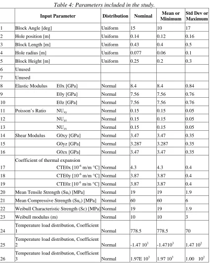
APPENDIX
Table 4: Parameters included in the study.
Input Parameter Distribution Nominal Mean or Minimum
Std Dev or Maximum
1 Block Angle [deg] Uniform 15 10 17
2 Hole position [m] Uniform 0.14 0.12 0.16
3 Block Length [m] Uniform 0.43 0.4 0.5
4 Hole radius [m] Uniform 0.077 0.06 0.1
5 Block Height [m] Uniform 0.25 0.2 0.3
6 Unused 7 Unused
8 Elastic Modulus E0x [GPa] Normal 8.4 8.4 0.84
9 E0y [GPa] Normal 7.56 7.56 0.76
10 E0z [GPa] Normal 7.56 7.56 0.76
11 Poisson’s Ratio NUxy Normal 0.15 0.15 0.05
12 NUyz Normal 0.15 0.15 0.05
13 NUzx Normal 0.15 0.15 0.05
14 Shear Modulus G0xy [GPa] Normal 3.47 3.47 0.35
15 G0yz [GPa] Normal 3.287 3.287 0.35
16 G0zx [GPa] Normal 3.47 3.47 0.35
17
Coefficient of thermal expansion
CTE0x [10-6 m/m °C] Normal 4.3 4.3 0.4
18 CTE0y [10-6 m/m °C] Normal 3.87 3.87 0.4
19 CTE0z [10-6 m/m °C] Normal 3.87 3.87 0.4
20 Mean Tensile Strength (Sut) [MPa] Normal 19 19 1.9
21 Mean Compressive Strength (Suc) [MPa] Normal 60 60 6
22 Weibull Characteristic Strength (Sc) [MPa] Normal 19 19 1.9
23 Weibull modulus (m) Normal 10 10 3
24
Temperature load distribution, Coefficient
1 Normal 778.5 778.5 70
25
Temperature load distribution, Coefficient
2 Normal -1.47 103 -1.47103 1.47 102
26
Temperature load distribution, Coefficient
Input Parameter Distribution Nominal Mean or Minimum
Std Dev or Maximum
27 Flux load distribution, Coefficient 1 Normal 30.6 30.6 5.00 10-2
28 Flux load distribution, Coefficient 2 Normal -9.22 -9.22 5.00 10-2
29
Dimensional Change, Parallel direction.
(flux scaling value) Normal 1 1 0.1
30
Dimensional Change, Parallel direction,
Magnitude Scaling Value Normal 1 1 0.1
31
Dimensional Change, Perpendicular
direction. (flux scaling value) Normal 1 1 0.1
32
Dimensional Change, Perpendicular
direction, Magnitude Scaling Value Normal 1 1 0.1
33 CTE Change. (flux scaling value) Normal 1 1 0.1
34 CTE Change, Magnitude Scaling Value Normal 1 1 0.1
35
Elastic modulus Pinning Term, Magnitude
Scaling Value Normal 1 1 0.1
36
Elastic modulus Structural Term,
Magnitude Scaling Value Normal 1 1 0.1
37
Young’s modulus Structural Term. (flux
scaling value) Normal 1 1 0.1
38
Secondary Irradiation Creep Coefficient
scaling value. Normal 1 1 0.1
REFERENCES
Iyoku, T., Ishihara, M., and Shirai, H., (1991), Journal of Nuclear Science and Technology, 28, 921
Judge, R. C. B., (1991), IAEA-TECDOC-690,
Judge, R. C. B., (1995), IAEA-TECDOC-901, 117-136
Koster, A., Matzner, D., and Nicholls, D. N., (2003), Nuclear Engineering and Design, 2800, 1-15
KTA, (1992), "KTA-3232 Keramische Einbauten in HTR-Reacktordruckbehälten, Sicherheitstechnische Regel des KTA", KTA-3232,
Mitchell, M. N., ( 2004), Presentation to Fifth International Nuclear Graphite Specialists Meeting, Plas Tan-Y-Bwlch, Maentwrog, Gwynedd, United Kingdom