Leak Before Break Procedure for High Temperature and Gas Fast Reactors –
Crack Opening Profile Studies for Complex-Shaped Defects in Thick Components
Cécile Krakowiak1), Yann Kayser2) and Hubert Deschanels3)
1) Commissariat à l'Energie Atomique CEN CADARACHE 13108 ST PAUL LEZ DURANCE Cedex France Tel: 33.4.42.25.38.83, Fax: 33.4.42.25.71.87, Email:[email protected]
2) Commissariat à l'Energie Atomique CEN SACLAY 91191 GIF sur YVETTE Cedex FRANCE Tel: 33.1.69.08.66.54, Fax: 33.1.69.08.87.84, Email: [email protected]
3) AREVA NP NEELFS – 10-12 Rue J. Récamier 69456 LYON Cedex 06 FRANCE Tel: 33.4.72.74.72.18, Fax: 33.4.72.74.73.25, Email: [email protected]
ABSTRACT
In order to develop defect assessment procedures and Leak Before Break (LBB) methods for high temperature applications, CEA, EdF and AREVA NP have conducted a large cooperative program in France. The calculation of crack opening area (COA) is of major importance in the LBB procedures, and advice on calculating the COA for postulated through-wall defects is given in A16 Appendix of the RCC-MR. However, solutions are poorly adapted to complex-shaped cracks, e.g. semi-elliptical through-wall cracks (TWC), where the crack length is largely greater on one surface than on the other, which appears to be characteristic of expected detectable defects in High Temperature Gas-cooled Reactor (HTGR) or in Gas Fast Reactor (GFR) components. Moreover, preliminary studies of LBB analyses on HTGR components evidenced the necessity to develop relevant Helium leak models for which the sole knowledge of the COA is not sufficient: a complete 3D description of the TWC geometry under loading is needed, in particular the so-called crack opening profile (COP) through the thickness.
The paper first presents an analytic formulation for the 3D geometry of a postulated circumferential, semi-elliptical through-wall defect in a tube, depending on the geometry and the thermo-mechanical loading of the structure, and based on the simplified assumptions of the current A16 Appendix of the RCC-MR [2]. Second, 3D Finite Elements calculations, that were performed in order to validate the proposed analytic description of defect opening, are described. Results of both the approaches are compared and discussed.
This work mainly shows that the present RCC-MR A16 appendix LBB procedure leads to significant overestimations of the size of expected detectable defects when applied to HTGR or GFR components, and that a reduction of margins might be justified. Further experimental and theoretical works are needed to answer the pending questions.
1- INTRODUCTION
The present work was performed in the frame of the mechanical assessment of the HTGR (High Temperature Gas-cooled Reactor) [1] and GFR (Gas Fast Reactor) structures and vessels. The objective is the application of the Leak Before Break (LBB) approach, according to the RCC-MR A16 procedure [2], to a HTGR or GFR component. This procedure being developed and validated for Sodium Fast Reactors, its main steps were reviewed in view of HTGR applications [3]. Preliminary application of the A16 LBB approach to a HTGR cross vessel [4] evidenced needs of further developments and validation. Cooperative studies were conducted at CEA, EdF and AREVA-NP during the past few years, aiming at improving the procedure to take account of the specificities of helium cooled reactors [5]. The main studies dealt with:
- the helium leak rate models (numerical models and experimental validation), for which the sole knowledge of the COA is not sufficient as a 3D flow channel description is needed,
- the evaluation of the validity range of the current method, - the description of the 3D geometry of the expected TWC.
The crucial point appeared to be the determination of the detectable defect (size and shape).
In support to a further experimental program foreseen at CEA, an analytic formulation was proposed to describe the 3D geometry of expected detectable defects with respect to the applied thermo-mechanical loading. This analytic formulation was then applied to a HTGR cross vessel, which gives 3D dimensions and shape of the expected detectable defects in such a component. The proposed formulation, which is based on the RCC-MR A16 method, is then compared to 3D Finite Elements calculations.
2- PRINCIPLE OF THE A16 LBB PROCEDURE (RECALLS)
The principle of LBB according to the French A16 approach is described in Fig. 1. The detectable TWC is determined in a detailed manner, as it is characterized by its dimensions on the inner and outer walls of the structure:
- the minimum size, 2CL, on the penetrated wall (outer wall), which corresponds to the detectable leak, - the maximum size, 2Cd, reached by the defect on the inner wall (where the defect initiated).
2ci (initial)
2cp (At wall breakthrough) 2cd (Detectable through-wall crack ; maximal length)
2cG (Length of critical through-wall-crack)
t
2cL (Detectable through-wall crack ; minimal length)
Fig. 1: Principle of the A16 LBB Procedure
Basically, it must be verified that the maximum size, 2Cd, of the detectable crack for which the leak will be measured during nominal conditions (i.e. under all 1st and 2nd category loadings), is less than the unstable crack, 2CG, estimated (by classical fracture mechanics approach) during all 3rd and 4th category loading:
2Cd < 2CG / α (1)
whereα is a margin coefficient. In the current A16 procedure, α has been fixed to 2.
The maximum defect size, 2Cd, is linked to the minimum crack size, 2CL, which in turn is related to the detectable leak rate, Qdet, taken equal to ten times the “minimum” experimental leak rate (Qdet = 10 Qmin). This value is an input data of the A16 procedure, and will not be dealt with in the present study.
More precisely, the elastic crack opening under nominal membrane and local bending stresses (respectively σm and σb) is calculated by:
(
m m b b)
L
el k k
E C
σ σ
δ =4 − assuming kmσm−kbσb >0 (2)
In Eq. (2), E is the Young’s modulus; and km and kb are shape factors coming from fracture mechanics and tabulated for plates in A16 appendix.
The corresponding crack area AL is commonly assumed to be an ellipse:
2 L L L
C
A =πδ (3)
The volumetric flow rate is proportional to the crack area and to the fluid velocity V, so that :
Qdet = AL V (4)
Combining Eq. (2), (3) and (4), lead to the relation between 2CL and Qdet:
) (
2 2 2
2
0 det
b b m m L
k k V
Q E C
σ σ πρ
ρ −
= (5)
Knowing the fluid velocity V, and its properties (density ρ0 in the primary containment vessel, and ρ2 at the crack area), leads to 2CL.
3- ANALYTIC FORMULATION FOR THE 3D CRACK GEOMETRY
As shown in Fig. 2, the crack can be characterized by its shape 2C(z) in the (x,z) plane, and its out-of-plane opening area A(z), both depending on the location z through the component thickness.
This 3D geometry, although complex compared to usual representations of cracks in fracture mechanics studies, is a simplified representation of the real crack.For instance, roughness and tortuousness are not taken into account. Generally speaking, such features are in connection with:
- the material grain size,
- crack growth under operating conditions.
2.CL
2.Cd
2.C(z)
δδδδ(z)
δδδδL
δδδδd
t
Leak Flow x
z y
Fig. 2: Description of the 3D Crack Geometry
By convention, it is postulated that:
- z = 0 on the “inner skin” of the defect, which means the skin where the defect initiated,
- z = t on the “outer skin” of the defect, which means the skin where the defect penetrated and was detected. Thus it can be written: 2C(z = 0) = 2Cd, and 2C(z = t) = 2CL.
3.1- In the Plane Defect Shape: Determination of 2C(z)
In the crack plane, it is assumed that the shape of the crack front remains elliptical after penetration, which appears a reasonable hypothesis as it has been confirmed by several experiments and calculations [3] [6] [7]. Consequently, one can express the size 2C(z) of the defect in its (x,z) plane, at the location z through the thickness, by the following expression:
2 2 2
2 2
. 1 . . 2 ) ( . 2
d L d d
C C C
t z C z
C = − − (6)
3.2- Out-of-Plane Defect Shape: Determination of δδδδ(z)
It is widely assumed that the elastic Crack Opening Area is an ellipse [8]. However, near the small breach of complex through wall crack, a plastic COA under a rectangular assumption is likely more relevant. It should be taken into account later if required, but neglected plastic effect is pessimistic. The elliptic assumption has been generalized through the thickness, so that the opening area A(z) at each location through the thickness can be written as follows:
( )
( ) ( )
4 2 . C z z z
A =πδ (7)
3.2.1- Elastic Opening according to A16
The present study is based on the expression of the elastic COD (Crack Opening Displacement), δel, as proposed in [2]:
∫
=C
el xf dx
C E
0 2
* . . .
. . 8σ
δ (8)
where:
- E* = E in plane stress conditions, or E* =
2
1−ν
E
in plane strain conditions (MPa),
- f = influence coefficient of the stress intensity factor KI (tabulated in RCC-MR A16 [2]),
- KI = f.σ. π.C (MPa.m1/2),
- C = half length of the crack (m),
- σ = nominal stress normal to the plane of the defect (MPa).
Eq. (8) is based on the assumptions that the structure is an infinite plane plate; the defect is a rectangular through-wall defect, of constant size 2C through the plate thickness; the crack is thin (limited opening) with an elliptical right section; the normal stress range in the plane of the crack is represented by a pressure, σ, acting on the crack edges, and the stress σ remains constant along the crack edges. Then the elastic energy released during crack growth from x = 0 to x = C (current half length of the defect) is expressed as the elastic work of the pressure σ acting along the edges of the crack.
The effect of local plasticity on the crack opening profile through the thickness should be taken into account near the crack front. This will be dealt with later if necessary.
3.2.2- Proposal of a General Expression for the Elastic Opening Profile through the Thickness
The idea is the extension of Eq. (8) to a complex-shaped TWC, in a plate or in a tube of thickness t. The expression, however established for plane plates, is supposed to be acceptable for tubes of “sufficient” mean radius (to be defined later). It is assumed that:
• the structure is crossed by a defect of any shape in its plane, defined by (x,z),
• the shape of the defect is defined by its length, 2C(z), in the right section z = Cst,
• the structure is submitted to a stress field, σ(z), normal to the plane (x,z) of the defect,
• the stress field σ(z) is uniform in the right section z = Cst,
• each right section z = Cst behaves independently from its neighbouring sections. Eq. (8) can be generalized according to the following expression:
( )
( )
( )
( )
( )
∫
=z C
el x f x dx
z C E
z z
0 2
*. . . .
. 8σ
δ (9)
3.2.3- Elastic Opening Profile induced by a Linear Stress Field
For a structure of thickness t submitted to a combined mechanical loading characterized by a membrane stress, σm, and a local bending stress, σb, the local stress in the right section z = Cst expresses as follows:
b m
t z t
z σ σ
σ .
2 . 2 )
(
− −
= (10)
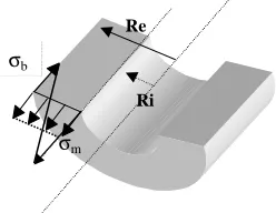
Figure 3 hereafter shows σm and σb in the axial direction of a tube of inner radius Ri and outer radius Re:
σb
σm
Re
Ri
Fig. 3: Axial Membrane and Bending Stresses in a Tube
Eq. (9) and (10) lead to the following expression :
( )
( )
= . . ] 2 -. 2 -. .[ ) ( . 4 ) (* m m b b
el k z
t z t z k E z C
z σ σ
δ (11)
where :
( )
( )
z xF( )
x dx C z k z C mm . . .
2
∫
( ) 02 2
= and
( )
( )
z xF( )
x dx C z k z C bb . . .
2
∫
( ) 0 2 2 = (12)Fm(x) and Fb(x) are the influence coefficients of the stress intensity factor KI for a through-wall defect of length 2x, submitted to a membrane stress, σm, and a local bending stress, σb:
(
F F)
xKI = σm. m+σb. b. π.2 (13)
• Fm and Fb, which can be obtained by Finite Elements calculations, are tabulated in RCC-MR A16 for many defect configurations.
• km and kb are given for limited configurations : mainly for rectangular through-wall defects in a plane plate. RCC-MR A16 compendium could be complemented by series of FE calculations if necessary.
In view of a general analytic formulation, it was chosen to simplify Eq. (11) according to the following equation:
= . . ] 2 -. 2 -. .[ ) ( . 4 ) (
* m m b b
el k t z t k E z C
z σ σ
δ (14)
where:
- k and m k are influence coefficients of an “equivalent rectangular defect”, defined by its constant length, 2C(zb eq), through the thickness,
- zeq = t/2 has been arbitrarily chosen. 3.3- Application to a HTGR Cross-Duct
The present study is based on data used for the first application of the RCC-MR A16 LBB procedure to a HTGR cross-duct, that was performed at CEA in 2003 [4]:
• the geometry of the cross-ductis a tube with an internal diameter of 2.3 m and a thickness of 0.1 m. The wall mean temperature is 440°C and the material is martensitic steel (9Cr1Mo mod, described in A3-18S of RCC-MR [2]). Thus, the creep effects are neglected.
• welds between the vessels and the cross-duct are circumferential, and the maximum stress is in the axial direction, so that we consider only circumferential cracks in this study,
• an internal pressure of 7.1 MPa is applied to the cross vessel, leading to a primary membrane stress of σm = 39.1 MPa in the axial direction,
• it is assumed that a temperature gradient of 13 to 26 °C will exist through the thickness of the pipe, giving a secondary local bending stress of σb = 20 to 40 MPa,
• the fluid velocity was determined assuming an adiabatic, laminar, compressible flow for a perfect gas in a permanent state.
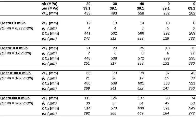
In addition, the detectable leak rate, Qdet, was parameterized: 3.3, 10, 100 and 300 m3/h were the selected values for the present study.
The A16 Methodology was followed, which lead to the determination, for various mechanical stress states (σm and σb), of: - the “just through-wall” crack lengths, 2Cp,
- the minimal and maximal lengths (respectively 2CL for the outer skin, and 2Cd for the inner skin) of the expected detectable defects, with respect to the detectable leak rate Qdet.
Then Eq. (14) was applied in order to determine the corresponding opening displacements (respectively δL and δd). Results are reported in Table 1 hereafter.
Table 1: Dimensions of the Expected Detectable Defects in a HTGR Cross-Duct, depending on the Detectable Leak Rate (Qdet) and on the Mechanical Loading (σσσσm and σσσσb), according to the RCC-MR A16 Approach and Eq. (14)
σσσσb (MPa) 20 30 40 0 0
σσσσm (MPa) 39.1 39.1 39.1 39.1 69.1
2Cp (mm) 433 493 558 282 282
Qdet=3.3 m3/h 2CL (mm) 12 13 14 10 8
(Qmin = 0.33 m3/h) δδδδL (µµµµm) 4 4 3 5 6
2 Cd (mm) 441 502 566 292 289
δδδδd (µµµµm) 247 312 393 129 233
Qdet=10.0 m3/h 2CL (mm) 21 23 25 18 13
(Qmin = 1.0 m3/h) δδδδL (µµµµm) 7 6 6 8 11
2 Cd (mm) 448 508 572 299 295
δδδδd (µµµµm) 251 317 398 132 230
Qdet =100.0 m3/h 2CL (mm) 66 73 79 57 43
(Qmin = 10.0 m3/h) δδδδL (µµµµm) 21 20 19 25 33
2 Cd (mm) 480 539 601 333 321
δδδδd (µµµµm) 269 341 422 147 250
Qdet=300.0 m3/h 2CL (mm) 115 126 137 98 74
(Qmin = 30.0 m3/h) δδδδL (µµµµm) 38 37 34 43 58
2 Cd (mm) 514 573 633 371 349
δδδδd (µµµµm) 292 366 449 164 272
Of course, the impact of the detectable leak rate, Qdet, can be observed for the different loading conditions: it can be noticed that it mainly affects the minimal lengths, 2CL, and corresponding COD, 2δL, of the detectable defects.
Besides, the just through-wall length, 2Cp, and the subsequent maximum length, 2Cd, of the detectable defects, mainly depend upon the bending to membrane stress-ratio: this effect is much more important than the detectable leak rate value on the defect maximal lengths and corresponding COD.
4- FINITE ELEMENTS 3D CALCULATIONS
3D Finite Elements (F.E.) calculations were performed under various thermo-mechanical loading conditions, and for different defect dimensions, in order to compare the obtained crack opening profiles (COP) to the corresponding predictions by Eq. (14).
4.1- Description of the F.E. Calculations
Elastic calculations were performed with the CAST3M F.E. computer code [9], which is developed at CEA.
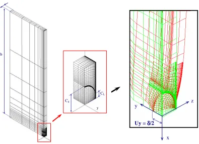
Plates were meshed, using the same data (thickness, material, mechanical loading) as reported in § 3.3. The plate width, 2b, was fixed equal to the circumference of the tube for the sake of further comparisons between plate and tube configurations. Due to symmetries, only 1/4th of the structure was represented. Specific displacement relations were used to connect the cracked part of the mesh to the rest of the plate.
The semi-elliptic through-wall defect was modeled as shown in Figure 4. 4 different defects were selected from Table 1:
• Defect 1: 2CL = 18 mm; 2Cd = 299 mm
• Defect 2: 2CL = 25 mm; 2Cd = 572 mm
• Defect 3: 2CL = 57 mm; 2Cd = 333 mm
• Defect 4: 2CL = 79 mm; 2Cd = 601 mm
Defect 1 and Defect 3 are the expected detectable defects in a 9Cr1Mo mod tube of inner diameter 2.3 m and thickness 100 mm, submitted to a cyclic axial membrane stress of 39.1 MPa at 440 °C of mean temperature, respectively for a detectable leak rate of 10 m3/h and 100 m3/h. Defect 2 and Defect 4 are the expected detectable defects in the same tube, submitted to a cyclic axial membrane stress of 39.1 MPa at 440 °C of mean temperature, and to a cyclic local bending stress of 40 MPa, respectively for a detectable leak rate of 10 m3/h and 100 m3/h.
For each case, the sensitivity of the results to the size of the mesh in the vicinity of the defect was studied.
t
b
Cd
CL
y
z
y
x
Uy =
δδδδ
/2
Fig. 4: Plate Model with Zoom of the Elliptic TWC, and Deformation under Traction (Defect 1 Behaviour)
4.2- Results and Discussion
The results were mainly analyzed in terms of COP through the thickness, for comparison to the corresponding predictions by Eq. (14). The present paper will only focus on results obtained for the plates, because the analytic formulation is based on the plate configuration: the effect of the ‘tube radius to thickness’ ratio is not considered here. Figure 4 also shows the behavior of Defect 1 in the plate submitted to pure traction along the y axis. The axial membrane stress is 39.1 MPa far from the through-wall defect.
COP through the Plate Thickness: F.E. Calculations / Eq. (14) Predictions
0,00 0,02 0,04 0,06 0,08 0,10 0,12 0,14 0,16 0,18 0,20 0,22
0 10 20 30 40 50 60 70 80 90 100
location z through the thickness : z=0 on the inner skin (great breach), z=100 on the outer skin (small breach) (mm)
h
al
f-o
p
en
in
g
U
Y
(
m
m
)
defect 4, Eq. (14) defect 4, CAST3M defect 2, Eq. (14) defect 2, CAST3M defect 3, Eq. (14) defect 3, CAST3M defect 1, Eq. (14) defect 1, CAST3M
Fig. 5: Crack Opening Profiles through the Plate Thickness for Defects 1, 2, 3 and 4
The COP through the plate thickness, obtained either by CAST3M F.E. calculations or by Eq. (14) analytic formulation, are compared in Figure 5 for the 4 defects considered in the study.
As far as the accuracy of the F.E. calculations can be relied upon, the analytic predictions appear globally satisfying for defects 1 and 3, which means for pure membrane loading situations, except near the small breach (near z=100 mm), where the opening is largely underestimated. The slope of the opening profile appears highly overestimated in case of bending stress (Defects 2 and 4), which implies an overestimation of the opening at the great breach and an underestimation of the opening at the small breach. Values at the great and small breaches are reported in the following Table 2.
The main result is that, whatever the configuration and the defect size, the current A16 method leads to an important underestimation of the crack opening at the small breach, e.g. at the outer skin, where the detection will be possible: by a factor 5 for the smaller defects (1 and 2) and by a factor higher than 2 for the larger defects (3 and 4). This means that, given the detectable leak rate, the minimal and maximal lengths, 2CL and 2Cd, of the detectable defect, are largely overestimated, which is safe of course, but might be too severe for HTGR or GFR applications.
Table 2: Great Breach and Small Breach Openings for Defects 1, 2, 3 and 4
CAST3M F.E. Calc. Eq. (14) Analytic CAST3M F.E. Calc. Eq. (14) Analytic
(µm) (µm) FE / Analytic (µm) (µm) FE / Analytic
Defect 1 128,7 131,7 1,0 38,8 7,9 4,9
Defect 2 309,7 397,9 0,8 31,5 5,8 5,4
Defect 3 141,9 147,2 1,0 58,6 25,0 2,3
Defect 4 324,4 422,5 0,8 48,3 19,1 2,5
Opening at the Great Breach δd Opening at the Small Breach δL
5- CONCLUSIONS
The present work was performed in the frame of the application of the A16 RCC-MR LBB procedure to HTGR and GFR components. First, a quite simple, analytic formulation is proposed to describe the 3D geometry of the expected detectable defects in such components –which knowledge is important for the determination of relevant helium leak rate models-, as a function of the applied mechanical loading. Second, corresponding Finite Elements 3D elastic calculations are described. The analytic formulation and the F.E. model are then applied to a HTGR cross-duct, in order to compare the both approaches on several defect shapes and sizes. It appears that the analytic formulation, which is based on the current LBB A16 procedure, systematically underestimates the crack opening at the small breach by a factor 2 to 5. These results have to be analyzed in terms of margins on the maximal size 2Cd of the expected detectable defects.
This work mainly shows that the present RCC-MR A16 appendix LBB procedure leads to significant overestimations of the size of expected detectable defects when applied to HTGR or GFR components, and that a reduction of margins might be justified. Further experimental and theoretical works are needed to answer the pending questions.
REFERENCES
1. Billot, Ph. and Barbier, D., « VHTR: Very High Temperature Reactor. The French Atomic Energy Commission (CEA) R&D Program », HTR2004, Beijing, China, September 22-24, 2004.
2. RCC-MR A16, « Design and Construction Rules for mechanical Component of FBR Nuclear Island », Tome I – Volume Z – Appendix A16 « Guide for Leak Before Break and Defect Assessment », Edition 2002 - AFCEN.
3. Deschanels, H., Drubay, B., Michel, B., Cambefort, P. and Marie, S., « Leak Before Break Procedure for High Temperature Applications – Improvements and Validation », ICAPP’03, Cordoba, Spain, May 4-7, 2003.
4. Lejeail, Y., Cabrillat, M.T. and Krakowiak, C., « Application of a Leak Before Break Procedure to a HTGR Cross Duct », HTR2004, Beijing, China, September 22-24, 2004.
5. Deschanels, H., Krakowiak, C., Kayser, Y., Simoneau, J.P. and Berton, J.L., “Leak Before Break Procedure for SFR Reactors and HTR Reactors – Improvements and Validation”, SMIRT 19, Toronto, Canada, August 12-17, 2007.
6. Kayser, Y., Marie, S., Poussard, Ch. And Delaval, Ch., « Leak before Break procedure – Recent Modifications of RCC-MR A16 Appendix and Proposed Improvements », Proposed at International Journal of Pressure Vessels and Piping, IPVP-D-07-00003, Under Review.
7. Ahn, S.H., Hidaka, A. and Ando, K., « Fatigue Crack Growth and Penetration Behavior in Pipe subjected to Bending Load », SMIRT 14, Lyon, France, August 17-22, 1997.
8. Paul, D.D., Ahmad, J., Scott, P.M., Flanigan, L.F. and Wilkowski, G.M., « Evaluation and Refinements of Leak-Rate Estimation Models », BATTELLE, Report NUREG/CR-5128, BMI-3164.
9. CAST3M Finite Elements Code, Web site: http://www-cast3m.cea.fr