Scholarship@Western
Scholarship@Western
Electronic Thesis and Dissertation Repository
9-27-2016 12:00 AM
Controlled Guidance of Light in Large Area Flexible Optical
Controlled Guidance of Light in Large Area Flexible Optical
Waveguide Sheets
Waveguide Sheets
Chloë O. Nicholson-Smith
The University of Western Ontario
Supervisor Dr. George Knopf
The University of Western Ontario Joint Supervisor Dr. Evgueni Bordatchev
The University of Western Ontario
Graduate Program in Mechanical and Materials Engineering
A thesis submitted in partial fulfillment of the requirements for the degree in Master of Engineering Science
© Chloë O. Nicholson-Smith 2016
Follow this and additional works at: https://ir.lib.uwo.ca/etd
Part of the Computer-Aided Engineering and Design Commons
Recommended Citation Recommended Citation
Nicholson-Smith, Chloë O., "Controlled Guidance of Light in Large Area Flexible Optical Waveguide Sheets" (2016). Electronic Thesis and Dissertation Repository. 4161.
https://ir.lib.uwo.ca/etd/4161
This Dissertation/Thesis is brought to you for free and open access by Scholarship@Western. It has been accepted for inclusion in Electronic Thesis and Dissertation Repository by an authorized administrator of
i
Abstract
Large surface area, thin, polymer optical waveguides are an emerging technology that
enable a wide variety of light collection and illumination systems to be created for
passive indoor lighting, mechanically flexible solar energy concentrators, and enhanced
safety lighting for motorized vehicles. This research builds on design of rigid
concentrator and diffuser waveguides, proposing and evaluating modifications for the
design of a flexible waveguide combining both concentrating and diffusing
functionalities. The waveguides are thin, mechanically flexible sheets with thicknesses in
the range of mm, and active surfaces that can range from a few cm2 to several m2.
Regions of the functional surface are designed to act as light concentrators, light
diffusers, light transmission conduits or some combination thereof. This research
examines how the geometry and spatial distribution of micro-optical features patterned
on a bi-layered thin polydimethylsiloxane (PDMS) waveguides can be used to guide
captured light rays through flat and flexible configurations. Zemax OpticStudio software
simulation tool is used to investigate the design parameters and the impact of these
parameters on concentrator and diffuser performance. A multi-functional
concentrator-diffuser waveguide is modelled and analysed in a study which shows the flat waveguide
has an overall efficiency of over 94%, however when it is modelled as a flexible
waveguide, less than 1% of the incident light is successfully guided. Various design
modifications to both the concentrating and diffusing regions of the waveguide are,
therefore, considered to mitigate these losses, and the efficiency of the flexible
waveguide is improved to nearly 60%. Based on the parametric optimization of the
microfeatures, the suitable waveguide design is identified for variations in the
waveguide’s flexibility, geometry, material and application. Future work will focus on
analyzing and optimizing the concentrator-diffuser waveguide design for enhanced
performance, thinner profile, and an evaluation of its empirical results.
Keywords
Flexible waveguide sheets, polydimethylsiloxane, large area concentrators, light
ii
Acknowledgments
This research is the result of collaboration between the University of Western Ontario
(London, Ontario) and National Research Council (London, Ontario). Partial financial
support was also provided by Natural Sciences and Engineering Research Council
(NSERC) of Canada and AUTO21 Network of Centers of Excellence. I would also like
to acknowledge the support of CMC Microsystems (Kingston, Ontario) in providing
iii
Table of Contents
Abstract ...i
Acknowledgments... ii
Table of Contents ... iii
List of Tables ... vii
List of Figures ... viii
List of Appendices ... xiv
List of Abbreviations and Symbols... xv
Chapter 1 Introduction ... 1
1.1 The Problem ... 2
1.2 Applications of Rigid and Flexible Light Guides ... 6
1.3 Research Motivation and Objectives ... 8
1.4 Design Issues... 9
1.5 Overview of the Thesis ... 10
Chapter 2 Literature Review of Optical Waveguide Sheets ... 13
2.1 Properties of Light ... 13
2.1.1 Light and Electromagnetic Spectrum... 13
2.1.2 Wave-Particle Duality of Light... 15
2.1.3 Transmission, Absorption and Reflection... 17
2.1.4 Geometric Optics ... 19
2.1.5 Limitations of Geometric Optics ... 20
2.2 Operating Principles of Flexible Optical Waveguides ... 23
2.2.1 Total Internal Reflection (TIR) in Waveguide Sheets ... 23
2.2.2 Structure of an Optical Waveguide Sheet ... 25
iv
2.3 Concentrators and Diffusers ... 33
2.3.1 Edge and Face Lit Waveguides... 33
2.3.2 Uniform and Non-Uniform Illumination ... 35
2.3.3 Selection of Core and Cladding Material... 37
2.3.4 Importance of Optical Microstructures ... 38
2.4 Key Material Properties of Optically Transparent Polymers ... 41
2.5 Concluding Remarks... 42
Chapter 3 Design Methodology ... 43
3.1 Evaluating Optical Waveguide Performance ... 43
3.1.1 Estimating Light Loss ... 43
3.1.2 Performance Measures ... 45
3.2 Role of Simulations in Optical Design ... 46
3.3 Functionality of Zemax OpticStudio Software ... 47
3.4 Limitations of Design Methodology ... 53
3.5 Concluding Remarks... 54
Chapter 4 Establishing Design Parameters for Large Area Waveguides... 55
4.1 Conceptual Design of Concentrator – Diffuser Waveguide ... 55
4.2 Waveguide Structure... 57
4.2.1 Waveguide Layering and Material Selection... 57
4.2.2 Waveguide Area and Thickness... 58
4.2.3 Microstructure Functionality... 59
4.3 Surface Area and Thickness... 61
4.4 Optical Microstructure Geometry ... 62
4.4.1 Various Shapes and Sizes ... 62
v
4.5 Equations for the Design of a Flat Waveguide ... 68
4.6 Performance of Functionally Designed Flat Waveguide ... 74
4.6.1 Single Microstructure... 74
4.6.2 Linear Array of Microstructures ... 76
4.6.3 Area Array of Microstructures ... 79
4.7 Discussion – Light Transmission Efficiency of Optimized Planar Waveguide ... 82
4.8 Concluding Remarks... 83
Chapter 5 Performance of Non-Rigid Waveguide Sheets... 85
5.1 Key Parameters and Waveguide Performance ... 85
5.1.1 Waveguide Parameters... 85
5.1.2 Concentrator Parameters ... 88
5.1.3 Diffuser Parameters... 93
5.2 Impact on Performance of Waveguide Bending ... 97
5.2.1 Waveguide Bending ... 98
5.2.2 Concentrator Bending ... 99
5.2.3 Diffuser Bending... 100
5.3 Microstructure Geometry for Non-Rigid Waveguide ... 102
5.3.1 Concentrator Geometry... 102
5.3.2 Diffuser Geometry ... 107
5.4 Evaluating Performance of a Non-Rigid Waveguide ... 111
5.4.1 Performance of the Concentrator as a Non-Rigid Waveguide... 111
5.4.2 Performance of the Diffuser as a Non-Rigid Waveguide ... 114
5.4.3 Combined Controlled Light Guidance and Distribution through Flexible Optical Waveguide Sheet... 115
vi
5.7 Concluding Remarks... 123
Chapter 6 Conclusions ... 125
6.1 Thesis Summary... 125
6.2 Concluding Comments... 126
6.3 Recommendations and Future Work ... 127
References ... 129
Appendices... 133
Appendix A: Derivations and Calculations... 133
Appendix B: CAD Drawings of Waveguide Geometry... 151
Appendix C: Sample Zemax Program ... 154
vii
List of Tables
Table 5.1 Data from Zemax simulations representing the uniformity and efficiency of the diffusing region with respect to the diffusing wedge angle (θd). ...93
Table 5.2 Summary of concentrator performance for variations in coupling features
geometry for both planar, and flexible waveguide orientations. ...107
Table 5.3 Summary of diffuser performance of the diffuser, with respect to its efficiency, in consideration of the various feature configurations. ...109
Table 5.4 Summary of the performance of the diffuser, with respect to its uniformity, in consideration of the various feature configurations. ...110
Table 5.5 Design guidelines for varying waveguide geometry according to the
requirements and limitations of a particular waveguide application. ...121
viii
List of Figures
Figure 1.1 Illustrations of large-area thin mechanically flexible waveguides for light harvesting and uniform illumination applications. Note that the thicknesses of the
waveguide regions are exaggerated for display. ...4
Figure 1.2 Cross-sectional view of a two layer PDMS concentrator-diffuser waveguide. The incident light is focused onto the coupling prisms by the micro-lens array, and
directed to the illuminating region, where the light is diffused by micro-wedge features. ...11
Figure 2.1 The electromagnetic spectrum encompasses various types of radiation which exhibits both electric and magnetic properties. Visible light occupies the mid-range of the
electromagnetic spectrum representing wavelengths from 400 to 700 nm...13
Figure 2.2 Depiction of an electron which falls from the outermost (highest energy) electron shell to a lower energy shell; it releases a packet of energy known as a photon.
This photon of energy is perceived as light. ...14
Figure 2.3 Young’s double slit experiment separated a light source into two wave fronts
whose interference pattern was projected onto a subsequent screen. The interference
pattern observed confirmed the wave properties of light. ...16
Figure 2.4 Light strikes the interface between two materials, with different refractive indices, it may traverse into the second medium by refraction, or be reflected back into
the first medium. ...18
Figure 2.5 Wave optics represents light as a wave which propagates outwards from a source, whereas geometric optics simplifies the source into rays travelling perpendicular
to the wave fronts. ...19
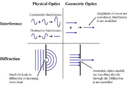
Figure 2.6 Geometric optics does not represent the behaviour of waves well at the micron scale. Interference and diffraction are not accounted for using geometric optics, as
ix
refractive index sufficiently larger than that of the cladding, as this will ensure the ray is
reflected off the boundary between the media. ...24
Figure 2.8 The critical radius of curvature of a waveguide represents the minimum radius to which a waveguide may be bent without the propagating light failing to reflect back
into the core, and being refracted out. ...25
Figure 2.9 The acceptance angle of a waveguide is defined by the maximum angle which can be contained in the waveguide by total internal reflection. Angles of incidence
greater than θa will not be contained in the waveguide core. ...29
Figure 2.10 The proportion of light lost due to bending relates to the degree to which the waveguide is bent past the critical radius. A smaller radius of curvature results in greater
light leakage. ...31
Figure 2.11 The edge-lit waveguide is illuminated from one side and diffuses incident light to illuminate the waveguide. The face-lit waveguide collects the light incident on the
face and directs it to one, or more, waveguide edges. ...34
Figure 2.12 A typical diffuser light source will illuminate a cone of light from the centre axis to the maximum angle. The concentrator illuminates the diffuser in a unique pattern
with light rays only propagating between a minimum and maximum angle. ...35
Figure 2.13 Uniform illumination of a diffuser waveguide is achieved by increasing the diffuser’s efficiency with distance from the source, as the light remaining in the
waveguide decreases [18]. ...36
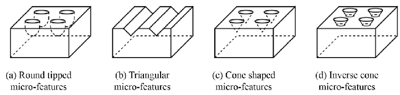
Figure 2.14 Commonly used diffuser micro-features include round tipped, triangular, cone shaped and inverse cone shaped features. ...39
x
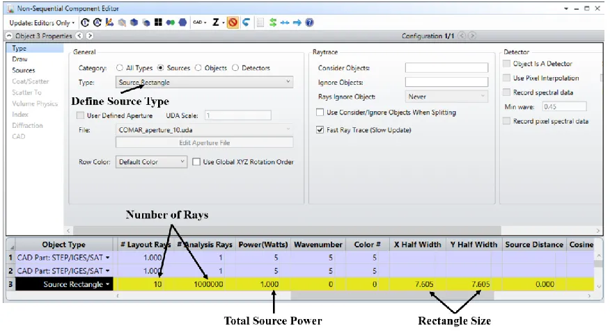
source, its total power, size and location. ...49
Figure 3.3 Zemax facilitates the definition of detectors and the relevant properties. ...51
Figure 3.4 Zemax represents the ray trace data in the 3D layout, providing a visual representation of the results. The detector data gives a more detailed view of the
illumination patterns and extensive numerical data. ...52
Figure 4.1 Combined concentrator-diffuser waveguide with lens micro-features focusing incident light onto the coupling prisms, which direct light into the transmission layer of
the waveguide. The light propagates to the diffusing wedges, which cause refraction. ...56
Figure 4.2 Illustration of the concentrator’s functionality; the concentrating lenses focus
the light onto the coupling prisms, which reflect the concentrated rays into the waveguide
at such an angle that they are confined to the bottom layer of the waveguide. ...60
Figure 4.3 The size and distribution of the wedge features must be optimized to enhance the uniformity of the diffuser’s illumination, and the length of the diffuser region must be
optimized for both its efficiency and uniformity. ...61
Figure 4.4 Illustration of concentrator and diffuser waveguide denoting important features; lenses, pyramids, and wedges, and their relevant parameters. ...68
Figure 4.5 Ray diagram for focused light incident on the coupling prisms, illustrating the minimum and maximum angles of incidence and propagation. ...70
Figure 4.6 Ray diagram which illustrates the minimum and maximum angles of propagation required to ensure the rays are properly diffused out the face of the
illuminating region. ...72
xi
strikes the wedge is successfully diffused, while the remaining incident light continues to
propagate through the diffuser. ...76
Figure 4.9 Detector data from the Zemax simulation of the row of concentrating features, showing light intensity patterns around the edges, and some illumination escaping the
bottom face of the concentrator. ...77
Figure 4.10 The Zemax simulation of the linear array of diffuser wedges demonstrates high efficiency, high intensity illumination of the waveguide’s face. ...78
Figure 4.11 Zemax results from the area array of concentrator micro-features demonstrated high efficiency collection of incident illumination with greater uniformity
over the collection region than previous results. ...80
Figure 4.12 Zemax simulation results displaying the illumination pattern and cross-sectional profile of the combined concentrator-diffuser waveguide...81
Figure 5.1 Relationship between the efficiency of the concentrating region (EC) and the
width of the concentrating region (WC) based on the results of Zemax simulations. ...86
Figure 5.2 Relationship between the ratio of the refractive indices of the waveguide layers and the efficiency of the waveguide, demonstrating a large drop in efficiency for
insufficient differences in refractive index. ...87
Figure 5.3 Relationship between the concentrator region’s efficiency and the Pitch (P) of the concentrator micro- features based on the Zemax results. ...88
Figure 5.4 Relationship between the concentrating region’s efficiency and the Radius (R) of the micro-lens features demonstrates a peak efficiency for the Radius as determined by
the parametric modelling of the lens dimensions. ...90
Figure 5.5 Relationship between the efficiency of the concentrating region, and the base
xii
coupling prisms. ...92
Figure 5.7 Results of Zemax simulations representing the relationship between the performance of the diffuser and the width (w) of the diffuser micro- features...94
Figure 5.8 Results of Zemax simulations representing the relationship between the performance of the diffuser and the total length (l) of the diffusing region. ...96
Figure 5.9 Relationship between the refractive index of the diffuser region and its efficiency and uniformity of illumination. ...97
Figure 5.10 Relationship between radius of curvature (C) of the waveguide and the efficiency, demonstrating a steep drop in efficiency for small radii of curvature. ...98
Figure 5.11 Relationship between the efficiency of the concentrator and its radius of curvature (C) comparing the use of a planar light source and a source which conforms to
the curvature of the waveguide. ...99
Figure 5.12 Relationship between the radius of curvature (C) and the performance of the waveguide, illustrating a large drop in both efficiency and uniformity of the diffuser for
small radii. ...100
Figure 5.13 Relationship between the radius of curvature (C) and the performance of the waveguide, illustrating the largest drop in efficiency for bending in the concentrator area. .101
Figure 5.14 Deformation of features due to bending of the waveguide results in misalignment between the focal point of the micro-lenses and location of the coupling
features. ...103
xiii
diffusing region as a whole are considered in order to optimize the waveguides
performance for each flexible and rigid configurations. ...108
Figure 5.17 The concentrator efficiency (Ec) of the simulated waveguide for various
bending radii (R) as determined by the Zemax OpticStudio ray-tracing software. ...112
Figure 5.18 Impact of waveguide bending changing the angle of incidence (θi) of light
rays entering the waveguide on concentrator efficiency. Note the rapid reduction in
efficiency as the angle of incidence is greater than 1o. ...113
Figure 5.19 The diffuser efficiency (Ed) of the simulated waveguide for various bending
radii (C) as determined by the Zemax OpticStudio ray-tracing software. ...115
Figure 5.20 The optimized geometry for the flexible concentrator-diffuser waveguide is modelled in SolidWorks and analyzed in Zemax in order to validate design. ...116
Figure A.1 Relationship between the lens feature pitch and the ray angle of incidence. ...141
Figure A.2 Relocation of focal point due to reorientation of lens micro-features with respect to the light source...144
Figure A.3 Reduction of the scale of the waveguide over the same range of curvature reduces the proportional deformation of the individual micro- features. ...149
Figure B.1 SolidWorks drawing of layered concentrator-diffuser waveguide, illustrating geometry used in Chapter 4 simulations. ...151
Figure B.2 SolidWorks drawing of concentrator micro-features illustrating radius, pitch, coupling feature and layer dimensions. ...152
Figure B.3 SolidWorks drawing of diffuser micro-features illustrating size and angle of the diffusing wedges, and diffuser region thickness. ...153
xiv
List of Appendices
Appendix A: Derivations and Calculations ...133 A.1: Derivation of Efficiency Equation
A.2: Relationship between Angle and Pitch
A.3: Calculation of Layer Thickness
A.4: Feature Stretching and Deformation
Appendix B: CAD Drawings of Waveguide Geometry ...151
xv
List of Abbreviations and Symbols
Abbreviations
MOS Micro-Optical Structure
PDMS Polydimethylsiloxane
BLU Backlight Unit
TIR Total Internal Reflection
LED Light Emitting Diode
NA Numerical Aperture
PV Photovoltaic
LGP Light Guide Plate
CAD Computer Aided Drafting
NSC Non-Sequential Component
Terminology
Collector
A collector is an optical device which increases the intensity of light, concentrating
incident light onto an area smaller than the region of incidence
Illuminator
An illuminator is an optical device which diffuses incident light evenly, over a region
larger than the area of incidence
Symbols
n Index of refraction
n1 Index of refraction of upper waveguide layer
n2 Index of refraction of lower waveguide layer
t1 Thickness of upper waveguide layer (mm)
t2 Thickness of lower waveguide layer (mm)
E Photonic energy (J)
h Planck’s constant (J·s)
xvi
λ Wavelength of light (nm)
θC Critical angle (°)
RC Critical radius of curvature (mm)
θa Acceptance angle (°)
D Lens diameter (mm)
f Lens focal length (mm)
EC Concentrator efficiency (%)
N Number of times a propagating ray strikes the waveguide’s bottom face
b Width of coupling prism base (mm)
P Pitch of concentrator micro-features (mm)
EC-D Efficiency of combined concentrator-diffuser waveguide (%)
LD Light diffused by illuminator region (W)
LC Light incident on concentrator region (W)
UD Uniformity of diffuser illumination (%)
Iavg Average detector irradiance (W/cm2)
Ipeak Peak detector irradiance (W/cm2)
α Base angle of coupling features (°)
hc Height of coupling features (mm)
θd Diffuser wedge angle (°)
w Diffuser wedge width (mm)
θi Angle of incidence of focused ray (°)
θP Ray angle of propagation (°)
CF Geometric factor of concentration
SA Waveguide surface area (mm2)
WC Concentrator width (mm)
ED Diffuser efficiency (%)
C Waveguide radius of curvature (mm)
θS Source angle of incidence (°)
DP Density of coupling features
xvii
θ2 Angle of focused ray in upper layer of waveguide (°)
θ3 Angle of focused ray in lower layer of waveguide (°)
x0 Position of incidence of ray on lens (mm)
m Slope of focused ray
xf X-position of micro-lens focal point (mm)
yf Y-position of micro-lens focal point (mm)
Chapter 1
Introduction
Current research on micro-patterned, large area optical waveguides has made significant
advances in the design of both concentrating and diffusing waveguides. Micro-patterned
concentrator waveguides are typically composed of two waveguide sheets; the upper
layer patterned with micro-lenses and the lower patterned with coupling prisms [1-5].
The micro-lens features focus the light incident on the upper layer onto the coupling
features in the lower layer. The coupling features reflect the light back into the
waveguide, by either total internal reflection (TIR) or reflection off a mirrored surface, at
such an angle that it propagates through the lower layer to the concentrator edge, where it
typically strikes a photovoltaic (PV) cell for solar collection.
Research in the design and development of micro-patterned diffuser waveguides is
significantly more extensive. Rigid diffuser waveguides have been examined with
various micro-feature patterns including: wedges [6], domes [7], grooves [8] and dot
features [9]. These waveguide configurations are often applied to backlight units (BLUs)
for electronic displays which are typically rigid structures, however there is some
research on flexible diffuser waveguides as well. Yeon et al. [10] look at the design of a
flexible diffuser waveguide patterned with inverse cone features. In all cases the diffusing
micro-features disrupt the path of the propagating illumination, such that it decouples
from the waveguide core and illuminates the diffuser face. This research on both rigid
and flexible micro-patterned waveguides provides the basis for the research which
follows.
The research presented in this thesis has two primary distinctions from the existing
work; it permits the design of mechanically flexible waveguides, and it accommodates
targeted illumination. There has been significant research in the field of flexible diffusers,
or light guide plates, and the designs and findings from this work are built upon in this
thesis. The design principles which may be extracted from existing research are the
general configuration of diffusing features and the geometry of the features themselves.
Essential to the uniformity of the diffuser’s illumination is the density of features with
respect to distance from the source. As well, previous research presents multiple potential
micro-features. While substantial research exists in the design of micro-patterned
diffusers, the diffuser region in the proposed waveguide is distinct in that it is illuminated
not by an external source, but by the concentrating region of the waveguide, and the
diffuser itself is mechanically flexible.
For the concentrating region, however, there is minimal research on the design of a
flexible micro-patterned waveguides, thus various adaptations on the design of a rigid
solar collector waveguides are considered, evaluated and optimized for the design of a
flexible concentrator. Although they only address the design of rigid, micro patterned,
concentrating waveguides the work of Karp et al. [5] and Thibault et al. [1] provide the
fundamental principles of functionality for the flexible waveguide too. The same
concentrating lens and coupling prism configuration will be applied, but altered and
optimized for the design of a flexible concentrator waveguide. The flexibility of the
waveguide enhances the versatility of the waveguide’s potential applications, while
reducing the invasiveness of the waveguide itself. A thin, flexible, large-area waveguide
could conform unobtrusively to the geometry of any underlying surface, and act as a
collector, illuminator, electronic display, optical sensor or any number of other
applications.
The other element of this research which differentiates it from similar work, is its
combination of light collection and diffusion, permitting the use of the concentrator’s
illumination as the source for the diffuser region of the hybrid waveguide. This
configuration permits the controlled guidance of light for targeted illumination by
accommodating the collection of light in the area of greatest ambient illumination,
transmission to the diffusing region, and illumination of the diffusing region at the target
location. This is essential for applications such as light harvesting, but is also ideal for
any application for which illumination is required in a low-light area.
1.1
The Problem
Large-area optical waveguides are a new technology that may significantly impact the
future of: wearable devices for light harvesting [11], optically based biosensors in
indoor lighting, signature and safety lighting on motorized vehicles [15], and non-planar
solar concentrators. These devices are constructed from one or more optically transparent
polymer sheets with thicknesses in the range of mm and surface areas that range of from
a few cm2 to several m2. Regions of the functionalized waveguide surface can be
designed to act as either light concentrator – collectors, light diffuser – illuminators,
and/or high efficiency light transmission conduits that perform like a fiber optic strand.
These thin polymer layers are constructed from materials that can be bent or even
modestly stretched without fracturing or losing their optical properties. The optical
performance of the large area waveguide is a function of the location and geometry of the
micro-optical structures (MOSs), thickness and shape of the flexible waveguide,
refractive indices of the constituent layers, and the characteristics of the incident light
source [5].
The non-rigid nature of the large area waveguide means that it can rest upon surfaces
with arbitrary geometry. Figure 1.1 illustrates a number of simple and more complex thin
large area optical waveguides including a simple curved (Figure 1.1a) light harvesting
waveguide with a square concentrator region surrounded by a diffuser that acts as an
illuminator [16]. More sophisticated designs where light is directed through a
transmission conduit to a distant illumination panel (diffuser) is shown in Figures 1.1b
and 1.1c. This basic design is used in solar capture systems that redirect sunlight into
buildings for natural illumination. The flexible waveguide sheet can also be made to
conform to an underlying three-dimensional geometry (Figure 1.1d). By careful selection
of the waveguide materials and design of micro-optical features on the active surfaces it
is possible to control the direction of light rays entering, propagating through, and exiting
(a) Small concentrator-diffuser waveguide. (b) Light harvesting indoor waveguide.
(c) Minimal loss light collecting waveguide. (d) Light harvesting automotive waveguide.
Figure 1.1 Illustrations of large-area thin mechanically flexible waveguides for light harvesting and uniform illumination applications. Note that the thicknesses of the
waveguide regions are exaggerated for display.
Although a variety of optically transparent materials can be used to create a large area
waveguide, the goal of the research reported in this thesis is on developing mechanically
flexible waveguides from polydimethylsiloxane (PDMS) [17]. These large area
waveguide sheets can be fabricated from PDMS using soft-lithography techniques.
PDMS has high optical transmittance properties (> 95%) over the visible and
near-infrared regions of the electromagnetic spectrum. Furthermore, the viscoelastic properties
pattern of the micro-features imprinted on the casting mould. This elastomeric material
also makes it possible to create multi-layered waveguide structures because the index of
refraction of the optically transparent PDMS can be controlled during fabrication by
either modifying the ratio of base to curing agent, adjusting the curing temperature or
time, applying deep ultra-violet irradiation, or adding high refractive index nanoparticles
such as titanium dioxide. In this manner the core and cladding layers can be moulded
separately and then bonded together using oxygen plasma or corona discharge bonding to
obtain total internal reflection over the prescribed working area of the waveguide.
Alternatively, it is possible to fabricate multiple PDMS layers through a multi-stage
curing process [17]. The fabrication process, however, is beyond the scope of this
research.
Current research on micro-patterned optical devices focuses on the design of rigid
planar waveguides. Some important conclusions can be drawn from the design of rigid,
large area micro-patterned concentrators and applied to the design of flexible
concentrators. Principally, the use of an array of micro-patterned lenses in one layer,
aligned with an array of coupling prisms in another layer, beneath the lens array, proves
to be the optimal configuration for a large area micro-patterned concentrator with a high
concentration ratio [4]. Another important conclusion which follows from the design of
rigid micro-patterned concentrators is the importance of minimization of the coupling
prism features to prevent losses of propagating rays. This presents an additional challenge
in the design of a flexible concentrator, as it significantly limits the acceptance angle of
the waveguide.
The research on flexible diffuser waveguides, while also limited, is significantly more
robust than that on flexible concentrators. The design of a micro-patterned diffuser has
two primary targets: illumination uniformity and light extraction efficiency. The
efficiency can be maximized by lengthening the diffuser, however this is detrimental to
the uniformity of the diffuser, and thus the light extraction efficiency must increase with
distance from the light source to maximize uniformity [18]. While previous research on
the design of flexible diffuser waveguides helps guide the design of the diffuser region of
the waveguide, there are some aspects of the hybrid collector-illuminator waveguide
The differences in the design of a rigid waveguide as compared to a mechanically
flexible waveguide are discussed in greater detail Chapters 4 and 5, but the primary
differences relate to the size, shape and distribution of the coupling prisms. By varying
the geometry and spatial distribution of the coupling prisms, the range of acceptance
angles of the concentrator, and thus the performance of concentrator undergoing bending,
is improved [19]. Another challenge which must be addressed in the design of
mechanically flexible concentrators and diffusers is the stretching and deformation of
micro-features due to waveguide bending. This challenge has not been significantly
investigated in relation to the design of a flexible waveguide however, it has been
demonstrated that for mechanically flexible features, the deformation can be limited by
reducing feature size.
The impact of design parameters on the performance of these non-rigid light guiding
structures is discussed and the parametric optimization of the size, shape, orientation and
position of the micro-optical features for maximum efficiency is investigated using
Zemax OpticStudio software. The appropriate geometry and spatial distribution of the
micro-optical features are, however, application dependent. To illustrate the concept of
controlled light guidance and distribution, a non-rigid PDMS waveguide (Figure 1.1a)
that performs both controlled light collection (concentrator) and targeted illumination
(diffuser) is introduced. For this study the concentrator region utilized an array of
focusing micro-lenses and reflecting micro-prisms. The radius, size and spatial
distribution of the lens features, and the size, location and shape of the reflecting features
will dictate the performance of the concentrator. In contrast, the diffuser is comprised of
reflecting wedge-shaped micro-features. Photo-sensors, photovoltaic cells or illumination
windows may be located at the light diffusing regions [5]. This design is analyzed and
optimized according to a theoretical application, and guidelines are presented for how the
design would best be modified for variations in geometry, material properties and
applications.
1.2
Applications of Rigid and Flexible Light Guides
Rigid concentrator and diffuser waveguides are predominantly used as solar collectors,
collectors as a means of collecting solar radiation, permits the focusing of sunlight onto a
smaller area of photovoltaic cell, minimizing the cost of the harvested energy [5].
Micro-patterned diffuser waveguides are commonly used as BLUs for electronic displays. The
implementation of a diffuser waveguide permits the use of a single light source at one
end of the display, which transmits illumination across the entire screen, via the diffuser.
This minimizes the size and cost of the displays, allowing for thinner, more compact,
electronic devices.
While there are many potential applications for rigid waveguides, by adding the
flexibility of the waveguides their applications become much more numerous. Flexible
waveguides would be able to conform to the geometry of their underlying surface, and
could unobtrusively form a waveguiding membrane on nearly any surface. Potential
applications include; wearable devices for light harvesting [11], optically based
biosensors in healthcare [12,13], flexible displays on clothing [14], sunlight capture
systems for passive indoor lighting [11], signature and safety lighting on motorized
vehicles [15], and non-planar solar concentrators. The flexibility of the waveguide is of
utmost importance in the consideration of wearable devices, as the waveguide must bend
and flex with the users’ movements if it is to be a viable, wearable, technology. In this
case, the waveguide may harvest incident light over the collecting region of the
waveguide, and transmit to the diffusing region for low light photo-therapy, displays on
clothing, or other wearable technology.
Light harvesting applications necessitate the combination of both the concentrating
and diffusing regions of the waveguide, and perhaps the addition of a transmission fiber.
This configuration allows the concentrator to act as the light source for the diffuser region
of the waveguide, permitting the illumination of the diffuser without the requirement for
any additional source or energy. This is ideal for solar applications, such as: indoor
lighting, automotive safety lighting or wearable displays. While these describe some of
the applications envisioned for the waveguide, its mechanical flexibility, combined with
the diversity of the concentrator-diffuser hybrid design, and the scalability of the product,
1.3
Research Motivation and Objectives
Although there is significant literature on the design, optimization, and application of
various micro-patterned concentrator and diffuser waveguides, there is little research on
the design of flexible waveguides. Flexible waveguides are very common in the field of
optical communication, particularly the use of fiber optic cables, however there is
minimal research on the design of flexible waveguides for light collection or
illumination. Fiber optic cables, while flexible, use typically rigid materials, commonly
silica glass, with a small enough fiber diameter that the waveguide is able to bend. This
technique could not be applied to the field of micro-patterned optical waveguides at the
materials used for fibers in this context, would be too brittle and render the waveguide
rigid. For this reason, among other challenges, there is very little research on the design
and fabrication of large area flexible waveguides, and this thesis will address some of the
shortcomings in this field, and how they can be overcome.
This research endeavors to design and optimize large area waveguides, incorporating
a large concentrating region of the waveguide, which collects and directs light to a small,
high intensity diffusing region, for targeted illumination. The objective of this research is
to identify appropriate geometry for the micro-optical structures patterning both the
concentrator and diffuser regions of the waveguide. These parameters are to be
parametrically optimized in order to identify the geometric and material properties for
which the waveguide is able to perform at maximum capacity.
One of the challenges, and benefits, of the proposed waveguide is its high degree of
adaptability. This ensures that the design may be applied for waveguides with various
shapes, sizes and applications, however the optimal geometrical parameters will vary in
each of these conditions. Where Chapter 4 will investigate and identify the optimal
waveguide for maximum performance, Chapter 5 will lay out how this design may be
adapted for various applications. The two parallel objectives of this research are: to
identify the geometric and material properties for maximum performance of a large area
waveguide for targeted illumination, and to establish design guidelines for modifying the
waveguide’s geometry according to the material and geometric constraints of a given
1.4
Design Issues
Although there exist many feasible designs for the development of large area flexible
waveguides, each design presents some challenges which must be addressed in the
optimization of a large area flexible waveguide. In the design of a typical diffusing
waveguide, or in this case a hybrid concentrator-diffuser waveguide, there are two
performance targets; efficiency and uniformity of output illumination. For the
concentrating region this means that the collection efficiency and transmission efficiency
must both be maximized, and for the diffusing region the light extraction efficiency and
uniformity must be maximized. Both the large area, and flexibility of the waveguide
present challenges in regards to optimization.
Creating a large area waveguide compromises the transmission efficiency, as the
longer a ray has to travel, the greater the likelihood that it is decoupled by a subsequent
feature, or absorbed by the material. To combat these losses, the coupling features should
be made as small as possible to prevent the decoupling losses, and the transmission
efficiency of the waveguide material must be optimized. Additionally, to ensure the rays
are confined to the propagation region of the waveguide, the waveguide layers must have
a sufficient difference in refractive indices, with the core having a significantly higher
index than the cladding. It is thus essential that the core is composed of an optically
transparent polymer with a high refractive index.
The flexibility of the waveguide presents numerous additional design issues which
must be considered. A flexible waveguide will undergo variations in geometry which will
affect the orientation of the light source with respect to the features, the orientation of the
lens features with respect to the coupling features, and the geometry of the micro-optical
features themselves. If the orientation of the concentrating features is unknown, with
respect to either the source or to each other, the acceptance angle of the coupling features
must be increased to accept the orientation of maximum deformation. This will
correspond with larger coupling features, and will in fact be a limiting factor in defining
the maximum flexibility of the waveguide. The deformation of the features themselves
must also be considered, stretching of the features on the outer surface of the bend, and
designed for applications with a great deal of bending, it must account for these changes
in geometry and positioning of the micro optical structures.
It is also important to note that some the solutions to the issues arising from
waveguide flexibility, contradict the design guidelines for a creating a large area
waveguide. For this reason, it is important to design a waveguide with the constraints of a
particular application in mind so that it can be optimized for the given conditions. The
design guidelines for creating the optimal waveguide for various conditions, are
presented in Chapter 5 of this thesis.
1.5
Overview of the Thesis
This thesis seeks to identify the ideal waveguide geometry for the controlled guidance of
light in both rigid and flexible waveguide sheets. The final design is composed of two
regions; the region of the waveguide sheet that acts as the light collector, or concentrator,
consists of two superimposed PDMS layers with slightly different indices of refraction.
The top layer is patterned with micro-lenses that focus the incident light rays onto the
pyramid features embedded in the second layer (Figure 1.2). The pyramid shaped feature
imprinted on the bottom surface of the second layer act as couplers which reflect the rays
and direct the light to the edge of the concentrator region. The difference in index of
refraction between the first (n1) and second layer (n2) ensures that the light rays striking
the pyramid micro-structures propagate laterally toward the concentrator edges by total
internal reflection [21]. The boundary region around the concentrator area of the
waveguide acts as a light diffuser, or illuminator. The bottom face of the PDMS layer for
the diffusing region is patterned with triangular-wedge shaped features that run the full
width of the waveguide. These optical wedges are angled such that when the propagating
rays strike the micro-feature surface they are reflected at an angle that causes the rays to
be refracted out of the layer surface.
Although there are specific design parameters for both the concentrator and the
diffuser, these regions of the waveguide must function in unison and therefore the
parameters must be optimized simultaneously to achieve the desired light ray
(t1+ t2) is determined by the focal length of the micro-lenses and the height of the bottom
layer (t2) is selected to ensure that all light rays can be efficiently transmitted from the
concentrator to the diffuser. In addition, the refractive indices for the two layers (n1 and n2) must be selected so that the rays that enter the bottom layer and reflect off the
coupling micro-features are forced to travel along the waveguide to the diffuser region.
Figure 1.2 Cross-sectional view of a two layer PDMS concentrator-diffuser waveguide. The incident light is focused onto the coupling prisms by the micro-lens
array, and directed to the illuminating region, where the light is diffused by micro-wedge
features.
This thesis is composed of six chapters, which address the design and parametric
optimization of a flexible large area optical waveguide. Chapter 2 explains the
fundamental concepts relating to the functionality of a flexible waveguide, and presents
an overview of the state of the art in the field of optical concentrators and diffusers.
Chapter 3 describes the design methodology used for the subsequent design and analyses.
It provides a description of the software used, how it was applied and its limitations, as
well as a summary of the metrics used to evaluate waveguide performance.
Chapters 4 and 5 describe the design, analysis and optimization of various
waveguides. Chapter 4 focuses on the design of an ideal, optimized waveguide, attaining
maximum efficiency for a rigid waveguide in a planar orientation. Chapter 5 looks at how
the ideal waveguide may be modified for enhanced performance in various conditions
and applications, particularly improving the performance of the flexible waveguide.
varied for optimal performance for any variations in constraints of the application. The
waveguide presented in Chapter 4 is optimized for high efficiency in ideal conditions and
attains efficiencies up to 95%. In Chapter 5, however the waveguide modelled is
somewhat more realistic, and much more adaptable, and thus the overall efficiency of the
waveguide falls closer to 60%. Finally, Chapter 6 offers conclusions based on the work
presented in this thesis, as well as recommendations for future work which could build on
Chapter 2
Literature Review of Optical Waveguide Sheets
2.1
Properties of Light
In order to effectively understand the functionality, and design a novel optical waveguide
sheet it is necessary to understand the fundamental properties of light, and how it
interacts with the media through which it travels. This section presents an overview of the
properties of the light as they relate to optical waveguides.
2.1.1 Light and Electromagnetic Spectrum
Light is a form of electromagnetic radiation, typically referring to the ultraviolet, visible
and infrared regions of the electromagnetic spectrum, represented in Figure 2.1, with
wavelengths from 10-400 nm, 400-700 nm and 750 nm-1 mm respectively [21]. Visible
light is the range of wavelengths which can be detected by the human eye, ranging in
colour from violet to red. Blues and violets lie at the lower end of the visible range with
shorter wavelengths, and higher energy, and reds and oranges at the upper end of the
visible spectrum, with longer wavelengths and less energy.
Figure 2.1 The electromagnetic spectrum encompasses various types of radiation which exhibits both electric and magnetic properties. Visible light occupies the mid-range
Typically, the light detected by the human eye is the actually being reflected off
objects, and perceived by our eyes, few objects are actually light sources. When object do
act as light sources, they emit light in the form of energy. This packet of energy, emitted
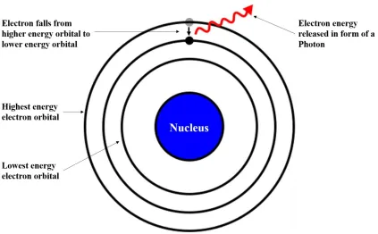
as light, is known as a photon, as seen in Figure 2.2. On an atomic level, when an
electron gains energy, or becomes excited, it jumps up to a higher orbital ring. This is a
temporary state of excitement, however, and when the electron falls back to a lower-level
shell, the excess energy is emitted as a photon.
Figure 2.2 Depiction of an electron which falls from the outermost (highest energy) electron shell to a lower energy shell; it releases a packet of energy known as a photon.
This photon of energy is perceived as light.
This fallen electron will have a particular photonic energy (E) which is related to the
distance which it falls [23]. The photonic energy is related to the wavelength of the
radiation by:
h
hc
where the energy E is a quantum of electromagnetic radiation, h is Planck’s constant of
6.6310-34 J-s and is the frequency of radiation. The frequency is
c where c is the
velocity of light (2.99108 ms-1) and is the wavelength of light in meters. As h and c
are both constants, the photonic energy is inversely proportional to the wavelength of the
radiation. The natural frequency of the material acting as the light source will dictate the
photonic energy released by the atom. For materials which emit radiation in the visible
range, the photonic energy released will be between 1.65 and 3.26 eV, corresponding to
wavelengths between 400 and 700 nm.
2.1.2 Wave-Particle Duality of Light
For centuries physicists have questioned the fundamental nature of light, settling over
time on two seemingly contradictory theories; light as a wave, and light as a particle. One
of the earliest descriptions of the wave properties of light appears in Christiaan Huygens’
1690 explanation of his undulatory theory, in which he speculated the vibrational nature
of light. Less than 15 years later, however, Isaac Newton contradicted Huygens’
undulatory theory, with a particle theory of light. Unlike the wave-theory, Newton’s
description could account for the ray-like properties of light, including propagation and
reflection [22].
While both theories had their merits and believers, neither could be proven nor
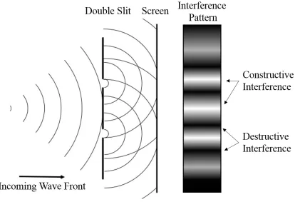
disproven, until Thomas Young conducted his famous double-slit experiment in 1801.
Young shone light through a small hole at a card with two slits cut in it side by side, and
observed the light patterns projected on a screen beyond the card. If the particle theory of
light were to hold up, it would be expected that the light would project directly out the
slits, forming an image mimicking the slit pattern. This is not what Young observed. He
saw, instead, that the light created bands of brightness and darkness on the screen, which
could only be explained by wave-theories of light. The waves emanating from the two
slits had created interference patterns, illuminating the screen where the waves exhibited
constructive interference and creating dark bands where the interference was destructive,
Figure 2.3 Young’s double slit experiment separated a light source into two wave fronts
whose interference pattern was projected onto a subsequent screen. The interference
pattern observed confirmed the wave properties of light.
Thanks to Young’s double slit experiment, it was widely accepted that light was in
fact a wave for the majority of physicists through the 19th century. That is, until the early
20th century, when Albert Einstein studied the photoelectric effect. Einstein observed that
when shining electromagnetic radiation onto a metal object, he was able to detect
electrons emanating from its surface. His proposed explanation was that the light struck
the metal’s surface in discrete packets of energy, photons. These photons strike the
surface, and transfer their energy to the atom, displacing an electron. This energy packet,
or photon, can either be absorbed, reemitted, or transferred through the material.
Einstein’s explanation of the particle theory of light, is still widely upheld, and forms the
basis for modern day quantum mechanics.
Neither the particle theory nor the wave theory, however, fully describes and predicts
properties of both a particle and a wave. This theory is known as the Wave-Particle
duality. It is often best to consider light as a wave for larger scale analyses of its
properties, while at an atomic scale, light is best treated as a particle.
2.1.3 Transmission, Absorption and Reflection
Although some objects behave as light sources, emitting light, the majority of media
serve to absorb, reflect or transmit light from external sources. Whether the light is
absorbed, transmitted, or reflected can also be explained by the behavior of the material
at an atomic level. It is best to consider light as a particle to explain its atomic behavior.
When a photon strikes a material’s surface, it will transfer its energy to the atom which it
hits. Depending on the properties of this material, the photon may be absorbed, reflected
or transmitted [23].
If the photon’s frequency is equivalent to the resonant frequency of the atom it
strikes, the atom will begin to vibrate, exciting neighbouring atoms, and eventually the
vibration dissipates the photon’s energy as heat. This results in the absorption of the incident photon, and also accounts for materials’ colours. For example, the resonant
frequencies of a red object will be equivalent to the frequencies of orange, yellow, green,
blue, indigo and violet photons, such that the only incident light that is not absorbed is
red.
If the photon strikes an atom with a frequency other than its resonant frequency, the
atom will momentarily absorb the energy, and an electron will jump to a higher orbital,
but in doing so will become unstable. To regain its stability, the electron will quickly fall
back to its original position, emitting a packet of energy, a photon, equivalent to that
which originally struck the atom. This photon may be reflected back towards the source,
or transmitted through the material. If the material is optically transparent, the photon is
reemitted by the atom, and strikes an adjacent atom, which briefly absorbs and then
reemits it. This is repeated throughout the material, transmitting the photon, and therefore
the light, through it. If a materially is opaque, it is unable to transmit the light through it,
but rather the photon is reemitted in the direction it came from, resulting in a reflection
reflection, but the degree to which they do each dictates the optical properties of the
material.
With an understanding of the quantum behavior of light, it is beneficial to consider its
wave properties as well, especially when contemplating the laws of reflection and
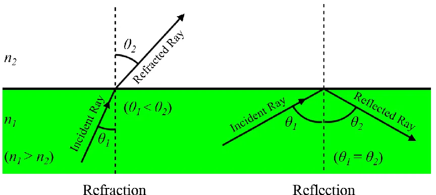
refraction. When a light waves strikes the interface between two materials it will either be
reflected off this surface, and travel back through the original medium, or traverse the
boundary and travel into the new medium. If it is reflected, it will travel back at an angle
(θ2) equivalent to that at which it struck the interface (θ1), whereas if it continues into the
new medium, it will continue travelling in the same direction, but at a slightly different
angle, as seen in Figure 2.4. This change in angle is known as refraction [24].
Figure 2.4 Light strikes the interface between two materials, with different refractive indices, it may traverse into the second medium by refraction, or be reflected back into
the first medium.
Although particle-theories of light offer an explanation for why light may be reflected
or refracted, they do not account for the path taken by the reflected or refracted photon.
Wave theory, however, provides a thorough understanding for the propagation of light
through various media. This highlights the importance of understanding the duality of
2.1.4 Geometric Optics
While the atomic-level properties of light are important in analyzing how it interacts with
a material, in the context of understanding and predicting the behavior of light in an
optical waveguide, it is primarily the large scale properties of light which are of concern.
In this case, the behaviour of light can be represented as a straight line, largely ignoring
the wave and particle properties of light, and considering it to be simply a ray. This is
known as geometric optics [24].
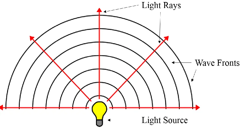
Figure 2.5 Wave optics represents light as a wave which propagates outwards from a source, whereas geometric optics simplifies the source into rays travelling perpendicular
to the wave fronts.
Geometric optics represents the propagation of light as a straight line through a
media, travelling perpendicular to the wave front, represented by the red rays in the above
Figure 2.5. While geometric optics fails to account for some of the micro- and
atomic-scale properties of light, it accounts for all of its macroscopic behaviour. Geometric
optics assumes that in any medium light will travel along its same path, until it reaches an
either be reflected back into the media from which it originated, or transmitted into the
new medium, according to the laws of total internal reflection.
Geometric optics provides a simple approach by which the path of a ray of light may
be predicted, according to its expected interaction with optical devices, such as mirrors
and lenses. This permits the analysis of an optical system without having to construct it,
as the path of a ray can easily be calculated according to the laws of reflection and
refraction, if the geometric and material properties of the system are known. This theory
is implemented in the Zemax OpticStudio software, which traces the ray path according
to geometric optics and can be used to analyze the functionality and performance of
various optical systems.
2.1.5 Limitations of Geometric Optics
Although geometric optics provides a simple and effective method of analyzing the
performance of optical systems, it is also important to appreciate the limitations of this
method. Because geometric optics neglects the consideration of the wave and particle
behaviour of light, some optical effects cannot be analyzed using geometric optics.
Notably, since the wave nature of light is not considered, the effects of interference and
diffraction cannot be assessed by ray optics [24].
As discussed above, interference occurs when two wave-fronts of light cross path
with each other. Where the crests or troughs of the wave meet the interference is
constructive, increasing the amplitude of the wave. Where a crest of one wave meets the
trough of another the interference is destructive, flattening the wave [25]. Diffraction
occurs when light interacts with an object with geometry close to, or smaller than, the
wavelength of light in consideration. The light wave interacts with the feature, such that
is causes some bending of the wave around the feature, typically emphasizing the
emanation of waves from this location [26]. Diffraction was prominently visible in
Young’s double-slit experiment. The experiment relied on the diffraction of the wave
through each slit, creating the two separate wave fronts, emanating from each slit, and
Figure 2.6 Geometric optics does not represent the behaviour of waves well at the micron scale. Interference and diffraction are not accounted for using geometric optics, as
the rays do not interact as such.
While these are both important optical effects, which must be understood, they can be
neglected in the geometric optics analysis of a waveguide under certain circumstances.
Because the effects of wave interference, and diffraction are most prominent for features
of the scale of the wavelength of light, if the geometry in consideration is substantially
larger than the wavelength of light, the effects are essentially negligible. These
limitations of the geometric optics analysis are illustrated in Figure 2.6. In order to apply
geometric optics analysis, the feature size of the relevant geometry should be no less than
10 times the wavelength of light, to mitigate the effects of interference and diffraction. In
the case of visible light, the wavelength is between 400 and 700 nm, therefore the
smallest dimensions should be no less than 7μm. When considering the possibility of
interference, the limiting dimension is the thickness of the waveguide layers, since if they