ELECTROMAGNETIC FIELD GENERATED BY A HORI-ZONTAL ELECTRIC DIPOLE ON A DOUBLE NEGATIVE MEDIUM HALF SPACE
X.-Q. Zhu †
School of Electronic Engineering Xidian University
Xi’an, Shaanxi 710071, China
W.-Y. Pan
China Research Institute of Radiowave Propagation Qingdao, Shandong 266071, China
B.-R. Guan
The Institute of Antenna and Microwaves Hangzhou Dianzi University
Hangzhou, Zhejiang 310018, China
Abstract—The electromagnetic field produced by a horizontal electric dipole over a double negative (DNG) medium half space is discussed, and the analytical expressions of the field which are convenient for calculation are derived. It can be concluded that the dipole on the configuration composed of the double positive (DPS) medium and the DNG medium half space can effectively excite the surface wave. The propagation wave number of the surface wave is less than that in both of the mediums, so that this kind of surface wave is a slow wave. Considered both the mediums are lossless, the amplitude of the surface wave decreases with the radial distance as 1/ρ1/2. The total field shows complicated interference because of the superposition of three kinds of wave modes.
Corresponding author: X.-Q. Zhu ([email protected]).
† Also with China Research Institute of Radiowave Propagation, Qingdao, Shandong
1. INTRODUCTION
In 1968, Veselago was the first to consider double negative materials (DNG) with both negative permittivity and negative permeability [1]. It was predicted that the material would exhibit many unusual properties such as inverted Snell’s law, Doppler shift and Cherenkov radiation. With the development of the fabricating technology of the DNG medium in recent years [2, 3], its distinctive physical characteristics have attracted considerable attention [4–7]. Moreover, it has been suggested that the material would have possible applications to the artificial dielectrics, lenses, antenna structure, optical and microwave components, sensors and frequency selective surface [8].
The frequency-domain electromagnetic field generated by an electric dipole near the boundary between two quite different material half-spaces has been investigated in the past decades owing to its wide ranging applications [9–18]. In addition, several groups have further studied the properties and applications of lateral pulses due to dipoles with delta-function and Gaussian pulse excitations in the time domain [18–23]. However, these works mainly focuse on how the wave behaves along the boundary of two kinds of double positive medium (DPS), i.e., both permittivity and permeability are positive. Quite recently, the electromagnetic waves over half-space DNG metamaterials excited by a infinite line source and a space-time wave packet have been treated in [7, 8]. Some interesting results, such as backward lateral waves and a small negative displacement of the reflected wave have been found. Therefore, it is worthwhile to theoretically investigate the new properties and phenomena of the electromagnetic field excited by a dipole in a DNG medium.
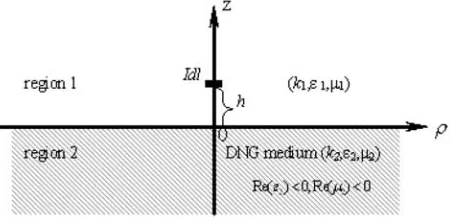
The goal of the present paper is to study the characteristic of the electromagnetic field generated by a horizontal electric dipole on the interface of a DNG and DPS medium. The geometry and notation underlying analysis are shown in Fig. 1. The horizontal dipole is located on the upward-directed z-axis at a distance h from the origin of coordinates on the interface, i.e., theρφ-plane. The electromagnetic field is to be determined at an arbitrary point (ρ, φ, z) in cylindrical coordinate. The upper half space is region 1 with DPS medium, the lower half space is region 2 with DNG medium.
2. INTEGRATED FORMULAS OF THE FIELD
Figure 1. Geometry of a horizontal electric dipole in the half-space.
formulas of the electromagnetic field in region 1 are described by
E1ρ(ρ, φ, z) = −ωμ
1Idl
4πk21
cosφ ∞
0
k12J0(λρ)−λ 2
2 [J0(λρ)−J2(λρ)]
×γ1−1eiγ1|z−h|λdλ+ ∞
0
γ1Q
2 [J0(λρ)−J2(λρ)]
− k21P
2γ1
[J0(λρ) +J2(λρ)]
eiγ1(z+h)λdλ
(1)
E1φ(ρ, φ, z) = ωμ
1Idl
4πk21
sinφ ∞
0
k21J0(λρ)−λ 2
2 [J0(λρ) +J2(λρ)]
×γ1−1eiγ1|z−h|λdλ+ ∞
0
γ1Q
2 [J0(λρ) +J2(λρ)]
− k21P
2γ1
[J0(λρ)−J2(λρ)]
eiγ1(z+h)λdλ
(2)
E1z(ρ, φ, z) = iωμ4πk1Idl2 1
cosφ ∞
0
±eiγ1|z−h|+Qeiγ1(z+h)
×J1(λρ)λ2dλ(3)
B1ρ(ρ, φ, z) = −μ14Idl
π sinφ ∞
0
+
∞
0
Q
2[J0(λρ) +J2(λρ)]
−P
2[J0(λρ)−J2(λρ)]
eiγ1(z+h)λdλ
(4)
B1φ(ρ, φ, z) =−μ14Idl
π cosφ ∞
0
±J0(λρ)eiγ1|z−h|λdλ
+
∞
0
Q
2[J0(λρ)−J2(λρ)]
−P
2[J0(λρ) +J2(λρ)]
eiγ1(z+h)λdλ
(5)
B1z(ρ, φ, z) = iμ41Idl
π sinφ ∞
0
eiγ1|z−h|−P eiγ1(z+h)
γ1−1J1(λρ)λ2dλ (6)
where Jn(λρ) is the Bessel function ofnth order, and the coefficients are defined as
Q = k21γ2−k22γ1
/k12γ2+k22γ1
(7)
P = (γ2−γ1)/(γ2+γ1) (8)
γ1 =
k2
1−λ2 (9)
γ2 = −
k2
2 −λ2 (10)
ki = ω√εiμi, i= 1,2 (11) For a DPS medium, both the real and imaginary parts ofkare positive. However, for a DNG medium, the real part of k is negative and the imaginary one is positive.
3. EVALUATION OF THE INTEGRALS
Let us now evaluate the integrals (1)–(6). As an example, it is convenient to rewrite (1) as
E1ρ=−ωμ4πk1Idl2 1
where Fρ0(ρ, z −h), Fρ0(ρ, z +h) and Fρ1(ρ, z +h) are defined as,
respectively
Fρ0(ρ, z−h) = ∞
0 γ
1
2 [J0(λρ)−J2(λρ)]
+k
2 1
2γ1
[J0(λρ) +J2(λρ)]
eiγ1|z−h|λdλ (13)
Fρ0(ρ, z+h) = ∞
0 γ
1
2 [J0(λρ)−J2(λρ)]
+k
2 1
2γ1
[J0(λρ) +J2(λρ)]
eiγ1(z+h)λdλ (14)
Fρ1(ρ, z+h) = ∞
0 γ
1
2 (Q+ 1)[J0(λρ)−J2(λρ)]
−k12
2γ1
(P−1)[J0(λρ) +J2(λρ)]
eiγ1(z+h)λdλ (15) (13) and (14) represent the direct and reflected wave, respectively, whose analytical results can be derived as [19]
Fρ0(ρ, z±h) =−k1eik1r
2k1 r2 +
2i r3 +
(z±h)2
r2
ik12 r −
3k1 r2 −
3i r3
(16)
in which,r =r1 = [ρ2+ (z−h)]1/2 for plus is the path length of the
direct wave, andr =r2 = [ρ2+(z−h)]1/2for minus is the path length of
the reflected wave. The third termFρ1(ρ, z+h) represents the surface
and lateral wave influenced by the boundary surface of two mediums. When the distance between the observation and source point is large and it is greater than that of source or observation and boundary, the integral converges very slowly because of the high oscillatory of the Bessel functions. It is not easy to get exact values by numerical methods. Thus, it is necessary to evaluate the integral by using the complex function method. For the two DPS medium configuration, many authors have studied and derived its approximation expressions. When Medium 2 is a DNG material, the electromagnetic field excited by a vertical dipole is discussed in [24]. Borrowed from the idea of [24], the first integrand term of (15) has a singular point on the λ
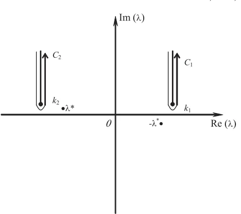
Figure 2. The configuration of the poles and the branch cuts.
complex plane. In addition, the integrand has two branch points at
λ = k1 and λ = k2. In order to evaluate the integral in (15), it is
necessary to shift the contour around the branch lines at λ=k1 and λ=k2. The configuration of poles and branch cuts is shown in Fig. 2.
Using the similar procedure as in [24],Fρ1(ρ, z+d) can be obtained by
determining the poles and evaluating the integration along the branch cuts C1 and C2.
Fρ1(ρ, z+h) = −ωμ1Idl
2π cosφ
iπγ1(λ∗)γ2(λ∗)λ∗
2N(λ∗)
×eiγ1(λ∗)(z+h) H0(1)(λ∗ρ)−H (1) 2 (λ∗ρ)
+k
2 1γ21
k22
2
k1πρe
ik1r2+iπ/4
π k1ρ
×
− eiπ/4√(z+h)
2ρ −A1
+iπA21e−iPd·erf c
−iPd
1 + i
k1ρ
+π
ρ
1
k1πρe
ik1r2+iπ/2e−iP0erf c−iP
−ei[k2ρ+γ12(z+h)]
1
k2ρ2
+ i
γ122 ρ3
+ i
k22ρ3
(17)
where
λ∗ = k1k2
k21+k22
(18)
γ1(λ∗) =
k12−λ∗2= k2
1
k2 1+k22
(19)
γ2(λ∗) = −
k22−λ∗2 =− k22
k2 1+k22
(20)
N(λ∗) = −
k22λ∗ γ1(λ∗)
+ k
2 1λ∗ γ2(λ∗)
= k
4 1−k24
k1k2
(21)
A1 = √ k1γ21
2k22ei3π/4
(22)
−iPd = −ik21ρ
k1γ21
k22
+z+h
ρ 2
(23)
−iP0 = −ik1ρ
2
γ21
k1
+z+h
ρ 2
(24)
γ21 = −
k22−k21 1/2
(25)
γ12 = i
k22−k21 1/2
(26)
erf c(x) = 1−Φ(x) = √2
π
∞
x
e−t2dt (27) and erf c(x) is the error function.
Similarly, the complete analytical expressions of the other components of the electromagnetic field can be obtained as follows:
E1φ = ωμ21Idl
π sinφ
−eik1r1
i r1 −
1
k1r12 − i k21r31
+eik1r2
i r2 −
1
k1r22 − i k12r23
+iπγ1(λ
∗)γ
2(λ∗)λ∗
2N(λ∗)
×eiγ1(λ∗)(z+h) H0(1)(λ∗ρ) +H (1) 2 (λ∗ρ)
−ik1γ21 ρk22
2
k1πρe
ik1r2+iπ/4
π k1ρ ×
−eiπ/4√(z+h)
+iπA21e−iPd·erf c
−iPd
+
πk1
ρ e
ik1r2e−iP0erf c−iP
0 1 + i
k1ρ
+ei[k2ρ+γ12(z+h)]
k2 γ122 ρ2
+ i
γ122 ρ3
+ i
k22ρ3
(28)
E1z = −ωμ21Idl
π cosφ
eik1r1
ik1 r1 −
3
r2 1
− 3i
k1r31
ρ
2k1r1 z−h
r1
−eik1r2
ik1 r2 −
3
r22
− 3i
k1r23
ρ
2k1r2 z+h
r2
+πγ2(λ
∗)λ∗2
2N(λ∗) e
iγ1(λ∗)(z+h)
H1(1)(λ∗ρ)
−ik21γ21 k2
2
1
k1πρe
ik1r2
π k1ρ
−iπA1e−iPd·erf c
−iPd
+ei
[k2ρ+γ12(z+h)] γ12ρ2
(29)
B1ρ=−μ21Idl
π sinφ
−eik1r1z−h
2r1
ik1 r1 −
1
r2 1
+eik1r2z+h
2r2
ik1 r2 −
1 r2 2 +iπk 2
1γ2(λ∗)λ∗eiγ1(λ
∗)(z+h) 2N(λ∗) H
(1)
0 (λ∗ρ) +H (1) 2 (λ∗ρ)
+k
2 1γ21 ρk2
2
2
k1πρe
ik1r2
π
k1ρ −iπA
1e−iPd·erf c
−iPd
+ik12
2
k1πρe
ik1r2−iπ/4
π k1ρ
−eiπ/4√(z+h)
2ρ −C1
+C12iπe−iP0 ·erf c
−iP0
1 + i
k1ρ
+e
i[k2ρ+γ12(z+h)] γ12ρ
k2
ρ + i ρ2 +
ik21 k2
2ρ2
B1φ=−μ21πIdlcosφ
−eik1r1z−h
2r1
ik1 r1 −
1
r21
+eik1r2z+h
2r2
ik1 r2 −
1
r22
+iπk
2
1γ2(λ∗)λ∗eiγ1(λ
∗)(z+h) 2N(λ∗) H
(1)
0 (λ∗ρ)−H (1) 2 (λ∗ρ)
−ik13γ21 k22
1
k1πρe
ik1r2
π
k1ρ −iπA1e
−iPderf c−iP
d
×
1+ i
k1ρ
+ik1
ρ
2
k1πρe
ik1r2−i3π/4
π k1ρ
−eiπ/√4(z+h)
2ρ −C1
+C12iπe−iP0·erf c
−iP0
+e
i[k2ρ+γ12(z+h)] γ12ρ
− k12 k2ρ
+ ik
2 1 k22ρ2
− i
ρ2
(31)
B1z=−μ21Idl
π sinφ
eik1r1
ik1 r1 −
1
r21
ρ
2r1 −e
ik1r2
ik1
r2 −
1
r22
ρ
2r2
−i
ρ2
π k1ρe
ik1r2e−iP0·erf c−iP
0
−k22ei[k2ρ+γ12(z+h)] γ122 ρ2
(32)
where
C1= γ 21
√
2k1ei3π/4
(33)
4. NUMERICAL RESULTS AND DISCUSSION
Thus, the complete analytical expressions of the electromagnetic field in the DPS medium excited by a horizontal dipole over the boundary of DPS and DNG mediums have been derived when|kρ| 1, ρhand
ρ |z|. As an example, each term in (17) is discussed to explain its physical conception. The first term indicates the surface wave propagating along the boundary of two different mediums. Its wave number is given by (18) and determined by the excited wave frequency and the physical parameters of two mediums. When Medium 1 is air and |k2| > k1, it can be seen from (18) that |λ∗| is smaller than the
wave number in Medium 1, so it is a kind of slow wave. As the distance between the observation and source point becomes large, the phase of the surface wave decreases and its amplitude for the lossless media attenuates as 1/ρ1/2due toHn(1)(λ∗ρ)≈[2/(πλ∗ρ)]1/2ei(λ
variation of surface wave withzis more slowly than that inρ direction because γ1(λ∗) is much smaller than k1 as |k2| k1. The second
and third terms indicate the lateral wave propagating with eik1ρ in Medium 1 along the surface. The fourth term represents the lateral wave propagating with eik2ρ in Medium 2. Because the real part of k2
is negative, its phase decreases with ρ. As the Medium 2 is lossy, it attenuates very quickly as the radial distance.
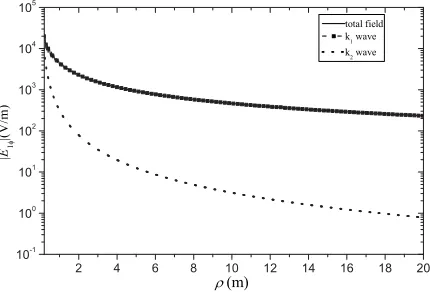
According to formulas (16)–(33) given above, we have performed our numerical calculations for the electric field components and its sub-components. The physical parameters used in our calculations are chosen as f = 1.2 GHz, Idl = 1 (A·m), z = h = 0. For convenience, the contribution of k1 wave in the following figures is the sum of the
direct, reflective and lateral waves in Medium 1. The contribution of
k2 wave indicates the lateral wave in Medium 2.
The amplitude of the electric fieldE1ρ(ρ,0,0) andE1z(ρ,0,0) has been numerically calculated as a function of propagation distance with
ε1r = μ1r = 1 and ε2r = μ2r = −1.1. The total field and its sub-components of E1ρ are illustrated in Figs. 3(a) and 3(b), respectively. Moreover, the calculation results forε2r= 1.21,μ2r= 1 are also given in Fig. 3(a). It can be seen that (1) The variation of the amplitude of
E1ρ with the distance is similar to that of E1z at φ = 0. Compared with the electric field component, the magnetic field component is so small that it is neglected in Fig. 2; (2) The surface wave can be effectively excited by the horizontal dipole in the surface of DPS and DNG mediums. Because of the contribution of the surface wave, the total field in this configuration is greater than that of two DPS medium configuration; (3) Because amplitude of the surface wave varies with radial distance as ρ−1/2, the contribution of the surface wave to the total field plays an important role for sufficiently large values ofρ. Asρ
(b)
Figure 3. The electric fieldE1ρ(ρ,0,0) and its sub-components as a function of the distance.
Figure 4. The electric fieldE1φ(ρ, π/2,0) and its sub-components as a function of the distance.
increases, the second term in (17) reduces toeik1ρ[1/(k1ρ2) +i/(k12ρ3)],
thus the lateral wave in Medium 1 decreases approximately as 1/(k1ρ2).
However, the lateral wave in Medium 2 decreases approximately as 1/(k2ρ2). Therefore, the contribution of lateral wave in Medium 1 is
greater than that in Medium 2 and attenuates slowly with the radial distance.
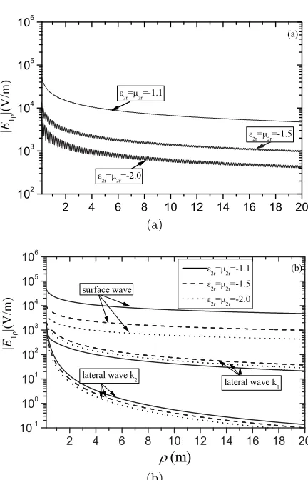
(a)
(b)
Figure 5. The electric fieldE1ρ(ρ,0,0) and its sub-components as a function of the distance.
lateral wave in Medium 1. The lateral wave in Medium 2 decreases quickly with the propagation distance. The contribution of the surface wave is smaller than that of lateral wave and is ignored. Moreover, the amplitude of the magnetic field component B1ρ(ρ, π/2,0) and
B1z(ρ, π/2,0) is much smaller than that of the electric field.
the surface wave with the physical parameters of the DNG medium. Because of the existing of three kinds of wave number, the total field shows complicated interference.
5. CONCLUSION
In this paper, the complete analytical expressions have been derived for the electromagnetic field generated by a horizontal electric dipole over the interface of the DPS and DNG mediums. Numerical calculations of the field components are performed and illustrated when both the dipole and observation point are located on the interface of two mediums. The influence of the physical parameters on the fields is also calculated and discussed. The main conclusions obtained in the present paper are summarized as follows.
(1) Comparing with the electromagnetic field induced by a horizontal dipole on the interface of two DPS material, the surface wave can be effectively excited on the interface of a DPS and DNG medium. The wave number of the surface wave is less than the wave number in Region 1 and Region 2, so that this kind of surface wave is a kind of slow wave, the amplitude of the surface wave for the lossless media decreases with the radial distance as 1/ρ1/2. The variation of the surface wave in the vertical direction of the interface is much more slowly than that in the radial direction as|k2| k1.
(2) The excited field is the superposition of the contribution of the direct, reflected, lateral and surface waves with three kinds of propagation wave numbers. The total field shows complicated interference because of the superposition of those waves.
(3) When the upper half space is air, the amplitudes of field componentsE1ρ, E1z andB1ϕ depend mainly on the contributions of surface wave, whose wave number is influenced by the physical parameters of the DNG medium in the lower half space. However, the contributions of the lateral waves play important role for the amplitudes of field componentsE1ϕ, B1ρ and B1z.
REFERENCES
1. Veselago, V. G., “The electrodynamics of substances with simultaneously negative values of ε and μ,” Sov. Phys. Usp., Vol. 10, No. 4, 509–514, 1968.
3. Simovski, C. R. and B. Sauviac, “Toward creating isotropic microwave composites with negative refraction,” Radio Sci., Vol. 39, No. 2, Rs2014.1–Rs2014.18, 2004.
4. Caloz, C., A. Sanada, and T. Itoh, “Microwave applications of transmission line based negative refraction index structures,”2003 Asia Pacific Microwave Conference, 2003.
5. Grbic, A. and G. V. Eleftheriades, “Subwavelength focusing using a negative-refractive-index transmission line lens,” IEEE Antennas and Wireless Propagation Letters, Vol. 2, 186–189, 2003. 6. Baccarelli, P., P. Burghignoli, and S. Paulotto, “Surfacewave suppression in a double-negative metamaterial grounded slab,”
IEEE Antennas and Wireless Propagation Letters, Vol. 2, 269– 272, 2003.
7. Thomas, J. R. and A. Ishimaru, “Wave packet incident on negative-index media,” IEEE Transactions on Antennas and Propagation, Vol. 53, No. 3, 1591–1599, 2005.
8. Ishimaru, A., J. R. Thomas, and S. Jaruwatanadilok, “Electro-magnetic waves over half-space metamaterials of arbitrary per-mittivity and permeability,”IEEE Transactions on Antennas and Propagation, Vol. 53, No. 3, 915–921, 2005.
9. Sommerfeld, A., “Propagation of waves in wireless telgraphy,”
Ann. Phys., Vol. 28, 665–736, 1909.
10. Sommerfeld, A., “Propagation of waves in wireless telgraphy,”
Ann. Phys., Vol. 81, 1135–1153, 1926.
11. Wait, J. R.,Electromagnetic Wave in Stratified Media, Pergamon Press, London, 1962.
12. Banos, A. J., Dipole Radiation in the Presence of a Conducting Half-space, Pergamon press, Oxford, 1966.
13. King, R. W. P., “New formulas for the electromagnetic field of a vertical electric dipole in a dielectric or conducting half-space near its horizontal interface,” J. Appl. Phys., Vol. 53, 8476–8482, Dec. 1982.
14. Wu, T. T. and King, R. W. P., “Lateral waves: A new formula and interference pattern,” Radio Sci., Vol. 17, No. 3, 521–531, 1982.
15. Wu, T. T. and R. W. P. King, “Lateral waves: New formulas for
E1φ and E1z,” Radio Sci., Vol. 17, No. 3, 532–538, 1982.
Vol. 72, No. 5, 595–611, 1984.
18. King, R. W. P., “Electromagnetic surface waves: New formulas and applications,”IEEE Trans. Antennas Propag., Vol. 33, No. 11, 1204–1212, 1985.
19. King, R. W. P., O. Margaret, and T. T. Wu, Lateral Electromagnetic Wave, Springer-verlag Press, 1992.
20. Wu, T. T. and R. W. P. King, “Lateral electromagnetic pulses generated by a vertical electric dipole on the boundary between two dielectric,” J. Appl. Phys., Vol. 62, 4345–4355, Dec. 1987. 21. King, R. W. P., “Lateral electromagnetic pulses generated by a
vertical electric dipole on a plane boundary between dielectric,”
J. Electro. Waves Appl., Vol. 2, No. 3–4, 225–243, 1988.
22. King, R. W. P., “Lateral electromagnetic pulses generated on a plane boundary between dielectrics by vertical and horizontal dipole source with Gaussian pulse excitation,” J. Electro. Waves Appl., Vol. 2, 589–597, 1989.
23. Li, K., Y. L. Lu, and M. H. Li, “Approximate formulas for lateral electromagnetic pulses from a horizontal dipole on the surface of one-dimensionally anisotropic medium,” IEEE Trans. Antennas Propag., Vol. 53, No. 3, 933–937, 2005.