Crosstalk Cancellation Method in a Complex Interconnection
Structure
Yafei Wang*, Huifang Sun, and Xuehua Li
Abstract—Complex interconnection structure is a common structure on printed circuit board (PCB). Herein, the paper proposes a method of crosstalk cancellation point at the crosstalk problem between microstrip lines in a complex interconnection structure. First, a model of the coupled transmission lines-channel transmission matrix (CTL-CTM) of the complex interconnection structure is established. Second, the CTL-CTM is simplified through the equivalence of crosstalk-coupling coefficient of parallel coupling microstrip lines to that of the complex interconnection structure. The eigenvalue of the simplified CTL-CTM is then decomposed, based on which the construction of crosstalk cancellation circuit is performed. Simulation results show that the proposed method can effectively improve the quality of eye patterns on complex interconnection structures.
1. INTRODUCTION
In the era of big data and terabit, data and information are growing exponentially, and requirements on the data-transmission bandwidth and speed of integrated circuit system interconnection continue to increase. Interconnection has greatly hindered the development of modern integrated circuit technology. A more advanced technology requires a higher working speed of the circuit, which means more serious interconnection problems [1]. Crosstalk is one of the most difficult problems in high-speed interconnection, crucially affecting signal quality on the transmission line. With increased speed and density, crosstalk is faced with new challenges in recent years. Reducing crosstalk in high-speed and high-density systems has become a research hotspot [2, 3].
In high-speed interconnection, electric field coupling and magnetic field coupling simultaneously exist between transmission lines, and crosstalk will be produced under their collective effect [4]. In electrical interconnection, microstrip lines are often used as interconnection structures. Crosstalk between microstrip lines is extensively investigated, but most of the studies focus on crosstalk analysis or crosstalk-reduction design between parallel microstrip lines [5–8]. However, in an actual interconnection design, there is few scenarios in which only parallel microstrip lines are used for layout design. Further applications of complex interconnection structure designs, such as Planar Meander Transmission Lines, parallel + non-parallel cascade, and irregularity [3, 9, 10], have been developed. As shown in Figures 1(a)–1(c), interconnection structures are common in PCBs and are often adopted. Existing studies focus on the parallel microstrip interconnection structure, as shown in Figure 1(a).
In this paper, crosstalk cancellation in Figures 1(b) and 1(c) is studied on the basis of a parallel microstrip interconnection structure. The CTL-CTM and crosstalk cancellation circuit of the complex interconnection structure are established through the crosstalk cancellation method of parallel microstrip lines based on CTL-CTM [11] to the complex interconnection. The usage of the crosstalk-coupling coefficient of the parallel-coupling microstrip lines is equivalent to that of the complex interconnection
Received 11 November 2019, Accepted 11 January 2020, Scheduled 29 January 2020
* Corresponding author: Yafei Wang ([email protected]).
1
2
3
4
1
2
3
4
1
2
3
4 (a)
(b) (c)
Figure 1. The interconnection structure on PCB.
structure. Method in channel transmission matrix simplification between non-parallel microstrip lines is also adopted. Advanced design system (ADS) simulation results show that the proposed method can effectively improve eye pattern quality in complex interconnection structures and expand the practical application of CTL-CTM crosstalk cancellation.
2. THE CTL-CTM OF COMPLEX INTERCONNECTION STRUCTURE
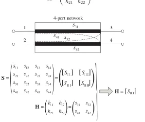
Establishing a CTL-CTM of a complex interconnection structure is the foundation of crosstalk cancellation. In high-speed interconnection, the S-parameter has the same physical meaning as channel transfer function, and they are both frequency-related coefficients [12]. Thus, a corresponding relationship exists between the S-parameters and CTL-CTM matrix elements on a set of two coupled microstrip lines, as shown in Figure 2.
In Figure 2, the CTL-CTM of the two coupled microstrip lines is shown. In Formula (1), the equivalence relationship between the elements of the CTL-CTM and theS-parameters is determined.
H=
h11 h12 h21 h22
(1)
11 12 13 14
21 22 23 24
31 32 33 34
41 42 43 44
=
s s s s
S S
s s s s
s s s s S S
s s s s
S =
S
H =
[ ]
11 12 31 32
21 22 41 42
=
h h s s
h h s s
H =
31
s
32
s
41s
42
s
1
2
4-port network
3
4
{
II I
[ ]
II I
[ ]
[ ] [ ]
I I I II
II II
(
(
(
(
(
(
(
(
A S B S 1 2 4 3 1' 2' 3' 4'
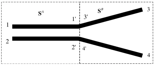
Figure 3. S-parameter model of complex interconnection structure.
whereinhi j =Sk+ij (1≤i, j ≤k, k=n/2, forn-port network).
A set of two coupled microstrip lines in the complex interconnection structure is shown in Figure 3. Directly solving S-parameter is difficult because the coupling of port 1 to port 4 involves coupling of parallel and non-parallel parts. This interconnection structure can be regarded as a cascade of two multiport networks, i.e., the cascade of two n port networks. First, the scattering matrix for each part is calculated, and the scattering matrix after the cascade is then synthesized. According to the correspondence between the CTL-CTM matrix element andS-parameter, the CTL-CTM of the complex interconnection structure can be obtained.
Before cascade, these two networks are respectively parallel and non-parallel with fixed angles coupled networks. Their scattering matrixes are relatively easy to be solved via the solution method of scattering matrix. The scattering matrix of these two networks is represented as
SA =
⎛ ⎜ ⎝
s11 s12 s11 s12
s21 s22 s21 s22
s11 s12 s11 s12 s21 s22 s21 s22
⎞ ⎟
⎠ (2)
SB =
⎛ ⎜ ⎝
s33 s34 s33 s34 s43 s44 s43 s44
s33 s34 s33 s34
s43 s44 s43 s44
⎞ ⎟
⎠ (3)
Represented in the form of a block matrix.
SA = S
A
I I SI IIA
SA
II I SII IIA
(4)
SB = S
B
I I SI IIB
SB
II I SII IIB
(5)
After the cascade of two networks, the resultant scattering matrix can be represented by the scattering matrix of the two networks before the cascade [13].
S =
[SI I] [SI II] [SII I] [SII II]
(6)
wherein [SI I], [SI II], [SII I], [SII II] are represented as in Formula (7).
⎧ ⎪ ⎪ ⎪ ⎨ ⎪ ⎪ ⎪ ⎩
[SI I] =SI IA+SI IIA [I]−SI IB SII IIA −1SI IB SII IA [SI II] =SI IIA [I]−SI IB SII IIA −1SI IIB
[SII I] =SII IB [I]−SI IB SII IIA −1SII IA
[SII II] =SII IIB +SII IB [I]−SBI I SII IIA −1SII IIA SI IIB
(7)
Accordingly, the CTL-CTM of a complex interconnection structure can be represented through the scattering matrix before the network cascade. As shown in Figure 2 and Formula (1), the CTL-CTM is as follows.
The matrix element value in Formula (8) can be calculated according to Formulas (2)–(7). Thus, the CTL-CTM of complex interconnection structure is determined.
3. DETERMINATION OF CROSSTALK CANCELLATION METHOD
3.1. Determination of CTL-CTM Element
The elements in CTL-CTM in the complex interconnection structure can be accurately obtained using Formula (8). However, matrix solution and further crosstalk cancellation circuit implementation will be complex. The elements in CTL-CTM are approximated, which can simplify the crosstalk cancellation method and circuit realization. This process allows non-parallel microstrip parts in the complex interconnection structure to be discretized intoN-segment parallel microstrip lines. Thus, each segment is the parallel microstrip line, and the complex interconnection structure approximates to the parallel structure. In comparison with the CTM construction of the parallel microstrip lines [14], the CTL-CTM with complex interconnection structure can still be constructed through the produce mechanism of crosstalk. Thus, CTL-CTM between the two coupling microstrip lines in the complex interconnection structure is as follows.
H=
h(ω) c(ω) c(ω) h(ω)
(9)
wherein h(ω) is the transfer function of the microstrip line; c(ω) is the far-end crosstalk transfer function; andc(ω) =−jωτh(ω), τ is the crosstalk-coupling coefficient.
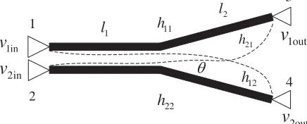
The corresponding crosstalk model of the complex interconnection structure is shown in Figure 4. Similarly, the CTL-CTM of the complex interconnection structure in Figure 1(b) can be identified.
1in
v
2in
v
1out
v
2out
v
1
2
11
h
12
h 21 h
4 3
22 h
θ
1
l
2 l
Figure 4. Crosstalk model of complex interconnection structure.
3.2. Determination of Crosstalk Coupling Coefficient
Crosstalk coupling coefficient is the key to determine CTL-CTM in complex interconnection structure. Theoretically, crosstalk between parallel and non-parallel microstrip lines depends on mutual capacitance and mutual inductance. Thus, if the attack signal and the characteristic impedance of the microstrip lines are consistent, the non-parallel transmission lines can be discretized into N-segment parallel microstrip lines, and each discrete segment can be regarded as an approximately parallel transmission line [15], as shown in Figure 5, so that crosstalk between one set of non-parallel microstrip lines is equivalent to crosstalk between another set of parallel microstrip lines.
0
s
s
ks
NFigure 5. A schematic diagram for discretization of non-parallel transmission lines.
1 2 3 4 5 6 7 8 9
0 10
-50 -40 -30 -20 -10
-60 0
dB (S(4,1))
s =160 mil θ = 5
f, GHz
Figure 6. Simulation comparison of far-crosstalk of parallel and non-parallel microstrip lines.
3.3. Crosstalk Cancellation Method
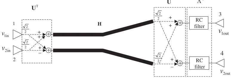
On the basis of the specific expression of CTL-CTM, the crosstalk cancellation scheme between parallel microstrip lines [11] can be transplanted into the complex interconnection structure for crosstalk cancellation. First, eigenvalue decomposition is made to the CTL-CTM matrix in the complex interconnected structure. Similar to the situation of parallel microstrip lines, the elements in the eigenvector matrix are all constant, which are all related with the frequency. Crosstalk cancellation circuit is then designed in accordance with these matrices, as shown in Formula (10). The non-crosstalk transmission can be realized if the corresponding circuit, such as UT, U, and Λ−1 are designed. The designed crosstalk cancellation scheme is shown in Figure 7
UTHUΛ−1=I (10)
whereinΛmatrix is formed by the eigenvalues ofHmatrix, andUmatrix is composed of the eigenvectors of Λmatrix.
1in
v
2in
v
1out
v
2out v
1
2
4 3
T
U
U Λ-1
H
2 2
2 2
2 2 2
2
RC filter
RC filter +
+ +
+
+
−
+
−
Figure 7. Crosstalk cancellation scheme for complex interconnection structures.
4. SIMULATION AND RESULT ANALYSIS
created, and the momentum simulator provided by the software is used to simulate the planar three-dimensional electromagnetic field of layout components. Then the layout components with practical physical meaning are introduced into the schematic interface to perform circuit simulation. Specific parameters are as follows: width of the microstrip line is 60 mil; near-end distance between adjacent microstrip lines is 30 mil; medium height is 32 mil; conductor thickness is t= 3 mil; dielectric constant εr = 4.5; magnetic permeability μr = 1; dielectric loss angle tangent tanδ = 0.02. The conductor is copper, in addition, the characteristic impedance of microstrip line is 50 Ω. On the basis of Figure 7, the layout of the artificial circuit is implemented. The component values of the first-order RC filter circuit can be treated according to the parallel microstrip lines and are then adjusted according to the simulation result. The transmission rate of input data on fixed microstrip line is set as 5 Gbit/s. The input data are a pseudo-random sequence, simulating eye diagram at the output end of the microstrip line before and after using the crosstalk cancellation method. Figures 8 and 9 illustrate the simulation results of the crosstalk cancellation method in the complex interconnection structures in Figures 1(b) and 1(c). As shown in Figure 8, the prerequisite for the simulation results is as follows. The length of the parallel part of the coupled microstrip line is 6 inches; the horizontal length of the angular part is 2 inches; and the intersection angle is curved. The simulation results indicate significantly decreased crosstalk jitter and amplitude distortion and good crosstalk cancellation effect.
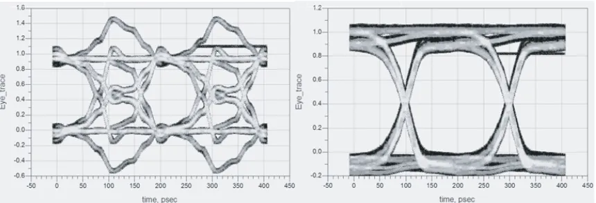
As shown in Figure 9, the prerequisite for the simulation results is as follows. The length of the parallel part of the coupled microstrip line is 4 inches; the horizontal length of the angular part is 4 inches; and the angle is θ = 5◦. The simulation results indicate significantly decreased crosstalk jitter and amplitude distortion and good crosstalk cancellation effect. The simulation results above verify the correctness of CTL-CTM construction in complex interconnection structure and the effectiveness of crosstalk cancellation method.
Figure 8. Comparison of the simulation result of crosstalk cancellation before and after (structure in Figure 1(b)).
5. CONCLUSION
To solve the problem of crosstalk between microstrip lines in complex interconnection structures, this paper proposes a crosstalk cancellation method by transplanting parallel microstrip lines. The equivalent of crosstalk-coupling coefficient is used to construct the CTL-CTM in the complex interconnection structure. Eigenvalue decomposition is then applied to the CTL-CTM to construct the crosstalk cancellation circuit. The proposed method is effective in crosstalk cancellation, simplifies crosstalk problems in complex interconnect structures, and expands the application range of CTL-CTM crosstalk cancellation.
ACKNOWLEDGMENT
This work is supported by the Young Scientists Fund of the National Natural Science Foundation of China (Grant No. 61601038).
REFERENCES
1. Mao, J. and M. Tang, High Speed Integrated Circuit Interconnection, Science Press, Beijing, 2017. 2. Halligan, M. and D. Beetner, “Maximum crosstalk estimation in, weakly coupled transmission
lines,”IEEE Transactions on Electromagnetic Compatibility, Vol. 56, No. 3, 736–743, 2014. 3. Gao, X., H. Zhang, P. He, et al., “Crosstalk suppression based on mode mismatch between
spoof SPP transmission line and microstrip,” IEEE Transactions on Components, Packaging and Manufacturing Technology, 1–7, 2019.
4. Paul, C. R., Introduction to Electromagnetic Compatibility, 2nd Edition, John Wiley & Sons, Inc., New Jersey, 2005.
5. Refaie, M. I., W. S. El-Deeb, and M. I. Abdalla, “A study of using graphene coated microstrip lines for crosstalk reduction at radio frequency,” Proceedings of the 35th National Radio Science Conference (NRSC), 85–90, Cairo, Egypt, March 20–22, 2018.
6. Xu, J. and S. Wang, “Investigating a guard trace ring to suppress the crosstalk due to a clock trace on a power electronics DSP control board,”IEEE Transactions on Electromagnetic Compatibility, Vol. 57, No. 3, 546–554, 2015.
7. Huang, B., K. Che, and C. Wang, “Far-end crosstalk noise reduction using decoupling capacitor,”
IEEE Transactions on Electromagnetic Compatibility, Vol. 58, No. 1, 1–13, 2016.
8. Balakrishnan, R., S. A. Thomas, and S. Sharan, “Crosstalk and EMI Reduction using enhanced Guard Trace Technique,” 2018 IEEE Electrical Design of Advanced Packaging and Systems Symposium (EDAPS), 1–3, Chandigarh, India, December 16–18, 2018.
9. Liu, X., Y. Li, Y. Zhao, et al., “Crosstalk reduction design and analysis of the planar meander transmission lines,”Proceedings of the 2018 International Symposium on Antennas and Propagation (ISAP), 1–2, Busan, Korea, October 23–26, 2018.
10. Quan, H. and Z. Sun, “Research on guard band to reduce the crosstalk for non-parallel microstrip lines,”Journal of Electronic Measurement and Instrument, Vol. 25, No. 10, 850–856, 2011.
11. Wang, Y. and X. Li, “Crosstalk cancellation method based on unitary transformation of coupled transmission lines-channel transmission matrix,” Progress In Electromagnetics Research Letters, Vol. 52, 45–50, 2015.
12. Li, P., Jitter, Noise, and Signal Integrity at High-Speed, Prentice Hall, New Jersey, 2008. 13. Liang, C.,Computing Microwave, Xidian University Press, Xian, 2012.
14. Wang, Y., “Crosstalk cancellation for non-parallel microstrip lines,”Journal of Microwaves, Vol. 34, No. 3, 65–68, 2018.