Mems Based Embedded Control System For Smart Walking
Assistance Device
Rowdooru Srikanth, V J Bharadvaja Sharma ,Y.Ravi Shankar
1Pg Student , 2 Assistant Professor ,3 Associate Professor Dept Of Ece Bheema Institute Of Technology And Science, Adoni, ApABSTRACT: This project presents the design and implementation of a unique control system for a smart hoist, a therapeutic device that is used in rehabilitation of walking. The control system features a unique human-machine interface that allows the human to intuitively control the system just by moving or rotating its body. The project contains an overview of the complete system, MEMS sensor is placed at the rods of the handle of the walking device and just by moving the rods we can control the walking device. MEMS sensor is one of the simplest but also most applicable micro-electromechanical systems. They became indispensable in automobile industry, computer and audio-video technology.
In this project MEMS sensor is used as the input to the microcontroller in order to control the walking device. Two MEMS sensors are used in order to indicate to the microcontroller the direction of movement of two wheels of the walking device. The output of the MEMS sensor is given to the microcontroller. Depending on the output from the MEMS sensor, microcontroller decides the direction of movement of wheels (either forward, backward, left or right). With this the person can move in the desired direction he needs.
I. INTRODUCTION
Hoist is a therapeutic device that was developed for the use in rehabilitation of walking after injuries or neural impairments. Rehabilitation of walking is a multi-step process that is aimed to return the freedom of motion to the patient. Is is a complex undergoing, mostly based on repetitive tasks execution . It starts with intense therapy of the muscular system and proceeds with the supervised static and dynamic balance training . The dynamic balance training is typically performed in presence of at least two expert therapist who manually assist the subject to walk and maintain the balance at the same time. Several technical solutions have been proposed to relieve the therapists from this physically intensive engagement, such as walking canes, simple static hoists, treadmill-based devices , robotic limb manipulators , movable support platforms etc.
The popularity of the assisted living research topics resulted in presentation of multiple similar devices that were designed for walking assistance to elderly people and those with motor disabilities. Such devices are usually based on a movable platform that is either actively steered or fully motorized and may combine additional features, such as active assistance for standing up and sitting down , or even help with other everyday tasks, such as picking up items . Most of these systems are controlled with the use of steerable handle bars or static handles, equipped with force sensors. Since gait and balance instability is one of the most common sources of fallinduced injuries , it is essential that the falls are prevented during the rehabilitation – systems that can not provide the support for patient‟s full body weight during a failure event (loss of balance, tripping, stumbling etc.) are not preferred since constant supervision and presence of the physiotherapist is required. The Hoist device prototype presented in this article provides a fail-safe and patient-engaging approach to gait rehabilitation. The paper is structured as follows. Section II introduces the designed walking assist control system, then a detailed description of the the rehabilitation platform that is built-upon in this research is given in the section III. The description of the base platform, hardware upgrades, embedded system and sensory system is given in separate sub-sections. The paper is concluded with the experimental results in Section IV and a short discussion of the results and the possible upgrades is included in the end.
II. LITERATURE REVIEW
Our research is focused on functional extension of an existing commercial rehabilitation platform named THERATrainer e-go, which was designed to offer the support for a strapped-in patient (device user) during the clinicalrehabilitation process. Previous work on this platform exposed a potential for a new, intuitive user-machine interface, that will be presented in this paper.
wheels are attached). The interface between the device chassis and the vertical support frame is made of a ball joint, equipped with adjustable coaxial springs that have limited range of motion in terms of off-vertical deflection angles. The interface enables the user a certain degree of freedom in motion, but it also limits the user‟s motion if needed in order to prevent injuries in cases of tripping, stumbling or falling.
The idea behind the Hoist project was to augment the manual control mode of the existing walking assist system by observing the patient and adapting the control strategy accordingly. For this purpose, user position determination and intention-based-control system was designed that allows the patient to control the motion of the device by perturbing its position in regards to the platform base. This approach equates to a very intuitive way of controlling the device, since the control system works towards maintaining the neutral position of the user in regards to the platform. The final result is a system that follows the
motion of the user, while providing constant fail-safe support forthe user.
A User position determination User‟s position in regards to the platform is determined by
observing the angles between the left/right (vertical) struts and the base frame . For this purpose, strutsand frame are equipped with bespoke tilt sensors , allowing the relative angles between the
frame and struts to be determined. The x-axis of the platform frame coordinate system is oriented towards the front of the device and the z-axis is oriented vertically in the up direction, while the y-axis is oriented towards the left side of the frame, creating a righthanded Cartesian coordinate system. While at rest, the tilt sensor coordinate system axes are aligned with the platform frame coordinate system. Deflection angles of the vertical support struts are mechanically limited to approximately 15_ from the vertical direction and the angular velocities of the struts are relatively low due to the long length of the struts. By using the small angle approximation of the trigonometric functions, rotation transformations between the platform frame coordinate system to tilt sensor coordinate system can be handled individually for the rotations around the x and y axes. Let denote the angle of rotation around the sensor‟s y axis that rotates the platform frame coordinate system to a tilt sensor coordinate system and denote the angle of rotation around the sensor‟s x axis that rotates the platform frame coordinate system to a tilt sensor coordinate system. When the user intends to speed up or slow down, user‟s speed will increase or decrease, respectively. This directly results in relative position
of the user in regards to the platform to change to more forward (user is accelerating) or more backwards (user is slowing down) position. When the user intends to change the direction of motion, the user will rotate his/her pelvis in that direction [10].Based on these assumptions, the values of _x and _ Y can be used directly as an estimation of user intent for acceleration and turning, while the side motion _y can be used as a measurement of the user‟s walking (gait) quality.
III. DESIGN OF HARDWARE
This chapter briefly explains about the Hardware implementation of authentication. It discuss the circuit diagram of each module in detail.
3.1 LPC2148 (ARM7) MICROCONTROLLER:
The LPC2148 microcontrollers are based on a 32 bit ARM7TDMI-S CPU with real-time emulation and embedded trace support, that combines the microcontroller with embedded high speed flash memory of 512 kB. For critical code size applications, the alternative 16-bit Thumb mode reduces the code by more than 30 % with minimal performance penalty.
Due to their tiny size and low power consumption, LPC2148 microcontrollers are ideal for the applications where miniaturization is a key requirement, such as access control and point-of-sale. A blend of serial communications interfaces ranging from a USB 2.0 Full Speed device, multiple UARTS, SPI, SSP to I2Cs and on-chip SRAM of 8 kB up to 40 kB, make these devices very well suited for communication gateways and protocol converters, soft modems, voice recognition and low end imaging, providing both large buffer size and high processing power. Various 32-bit timers, single or dual 10-bit ADC(s), 10-bit DAC, PWM channels and 45 fast GPIO lines with up to nine edge or level sensitive external interrupt pins make these microcontrollers particularly suitable for industrial control and medical systems.
3.1.1. FEATURES OF LPC2148
MICROCONTROLLER:
¢ 16/32-bit ARM7TDMI-S microcontroller in a tiny LQFP64 package.
¢ 8 to 40 kB of on-chip static RAM and 32 to 512 kB of on-chip flash program memory.
¢ 128 bit wide interface/accelerator enables high speed 60 MHz operation.
¢ In-System/In-Application Programming (ISP/IAP) via on-chip boot-loader software. Single flash sector or full chip erase in 400 ms and programming of 256 bytes in 1 ms.
Real Monitor software and high speed tracing of instruction execution.
¢ USB 2.0 Full Speed compliant Device Controller with 2 kB of endpoint RAM.
¢ In addition, the LPC2146/8 provide 8 kB of on-chip RAM accessible to USB by DMA.
¢ One or two (LPC2141/2 vs. LPC2144/6/8) 10-bit A/D converters provide a total of 6/14 analog inputs, with conversion times as low as 2.44 ?s per channel.
¢ Single 10-bit D/A converter provides variable analog output.
¢ Two 32-bit timers/external event counters (with four capture and four compare
channels each), PWM unit (six outputs) and watchdog.
¢ Low power real-time clock with independent power and dedicated 32 kHz clock input. ¢ Multiple serial interfaces including two UARTs (16C550), two Fast I2C-bus
¢ (400 kbit/s), SPI and SSP with buffering and variable data length capabilities.
¢ Vectored interrupt controller with configurable priorities and vector addresses.
¢ Up to 45 of 5 V tolerant fast general purpose I/O pins in a tiny LQFP64 package.
¢ Up to nine edge or level sensitive external interrupt pins available.
¢ 60 MHz maximum CPU clock available from programmable on-chip PLL with settling time of 100 ?s.
3.2. BLOCK DIAGRAM OF LPC2148
MICROCONTROLLER:
Fig: 1. Block Diagram Of Lpc2148 Microcontroller
3.2.1. DESCRIPTION ABOUT THE BLOCK DIAGRAM:
¢ On chip Flash Program Memory :
" LPC 2148 is having 512kB Flash memory. This memory may be used for both code and data storage. Programming of the flash memory may be accomplished in several ways(ISP/IAP).
¢ On chip Static RAM :
" On-chip static RAM may be used for code and/or data storage. The SRAM may be accessed as 8-bit, 16-bit, and 32-bit. An 8 kB SRAM block intended to be utilized mainly by the USB
¢ Interrupt Controller :
" The Vectored Interrupt Controller (VIC) accepts all of the interrupt request inputs and categorizes them as Fast Interrupt Request (FIQ), vectored Interrupt Request (IRQ), and non-vectored IRQ as defined by programmable settings.
¢ Analog to Digital Converter :
" LPC2148 contains two analog to digital converters(ADC0 & ADC1 ). Total number of available ADC inputs is 14. These two ADC's are 10 bit successive approximation analog to digital converters. Measurement range of 0 V to VREF. Global Start command for both converters.
¢ Digital to Analog Converter :
" The DAC enables to generate a variable analog output. The maximum DAC output voltage is the VREF voltage. 10-bit DAC. Buffered output. Power-down mode available.
¢ USB 2.0 Device Controller :
" The USB is a 4-wire serial bus that supports communication between a host and a number (127 max) of peripherals. Enables 12 Mbit/s data exchange with a USB host controller. A DMA controller (available only in LPC2146/48) can transfer data between an endpoint buffer and the USB RAM.
¢ UART :
" LPC2148 contains two UARTs( UART0 & UART1). In addition to standard transmit and receive data lines, the LPC2148 UART1 also provides a full modem control handshake interface. 16 byte Receive and Transmit FIFOs. It contains Built-in fractional baud rate generator covering wide range of baud rates without a need for external crystals of particular values.
¢ I2C-bus serial I/O controller :
¢ SPI serial I/O control :
" It is s a full duplex serial interface, designed to handle multiple masters and slaves connected to a given bus. Synchronous, Serial, Full Duplex Communication.
¢ SSP serial I/O control :
" Supports full duplex transfers. Data frames of 4 bits to 16 bits of data flowing from the master to the slave and from the slave to the master. Synchronous serial communication. Master or slave operation. 8-frame FIFOs for both transmit and receive. Four bits to 16 bits per frame
¢ Timers :
" LPC 2148 has two 32-bit timer/counters with a programmable 32-bit prescaler. It also having external External event counter. Four 32-bit capture channels per timer/counter that can take a snapshot of the timer value when an input signal transitions. A capture event may also optionally generate an interrupt.
¢ Watchdog Timer :
" The purpose of the watchdog is to reset the microcontroller within a reasonable amount of time if it enters an erroneous state. When enabled, the watchdog will generate a system reset if the user program fails to 'feed' (or reload) the watchdog within a predetermined amount of time.
¢ Real Time Clock :
" The RTC is designed to provide a set of counters to measure time when normal or idle operating mode is selected. The RTC has been designed to use little power, making it suitable for battery powered systems where the CPU is not running continuously (Idle mode).
3.3 PIN DIAGRAM OF LPC 2148 MICRO CONTROLLER:
Fig:3. Pin Diagram Of Lpc2148 Microcontroller
3.4RS232 CABLE:
To allow compatibility among data communication equipment, an interfacing standard called RS232 is used. Since the standard was set long before the advent of the TTL logic family, its input and output voltage levels are not TTL compatible. For this reason, to connect any RS232 to a microcontroller system, voltage converters such as MAX232 are used to convert the TTL logic levels to the RS232 voltage levels and vice versa.
3.5. MAX232 IC:
Max232 IC is a specialized circuit which makes standard voltages as required by RS232 standards. This IC provides best noise rejection and very reliable against discharges and short circuits. MAX232 IC chips are commonly referred to as line drivers.
Fig:4. Pin diagram of MAX232 IC
3.6. POWER SUPPLY:
The power supplies are designed to convert high voltage AC mains electricity to a suitable low voltage supply for electronic circuits and other devices. A power supply can by broken down into a series of blocks, each of which performs a particular function. A d.c power supply which maintains the output voltage constant irrespective of a.c mains fluctuations or load variations is known as "Regulated D.C Power Supply".
Fig:5 Block Diagram of Power Supply
3.7.MEMS SENSOR
Micro electro mechanical systems (MEMS, also written as micro-electro mechanical, Micro Electro
Mechanical or microelectronic and micro electro mechanical systems and the related micro mechatronics) is the technology of microscopic devices, particularly those with moving parts. It merges at the nano-scale into nano electro mechanical systems (NEMS) and nanotechnology. MEMS are also referred to as machines in Japan, or micro systems technology (MST) in Europe.
MEMS are made up of components between 1 and 100 micrometres in size (i.e., 0.001 to 0.1 mm), and MEMS devices generally range in size from 20 micrometres to a millimetre (i.e., 0.02 to 1.0 mm), although components arranged in arrays (e.g., digital micro mirror devices) can be more than 1000 mm2. They usually consist of a central unit that processes data (the microprocessor) and several components that interact with the surroundings such as micro sensors.[1] Because of the large surface area to volume ratio of MEMS, forces produced by ambient electromagnetism (e.g., electrostatic charges and magnetic moments), and fluid dynamics (e.g., surface tension and viscosity) are more important design considerations than with larger scale mechanical devices. MEMS technology is
distinguished from molecular
nanotechnology or molecular electronics in that the latter must also consider surface chemistry.
The potential of very small machines was appreciated before the technology existed that could make them (see, for example, Richard Feynman's famous 1959 lecture There's Plenty of Room at the Bottom). MEMS became practical once they could be fabricated using modified semiconductor device fabrication technologies, normally used to make electronics. These include molding and plating, wet etching (KOH, TMAH) and dry etching (RIE and DRIE), electro discharge machining (EDM), and other technologies capable of manufacturing small devices.
Fig6:MEMS Sensor
The fabrication of MEMS evolved from the process technology in semiconductor device fabrication, i.e. the basic techniques are deposition of material layers, patterning by photolithography and etching to produce the required shapes.
Fig7: circuit diagram of MEMS sensor
3.8. DC MOTOR
A DC motor is any of a class of rotary electrical machines that converts direct current electrical energy into mechanical energy. The most common types rely on the forces produced by magnetic fields. Nearly all types of DC motors have some internal mechanism, either electromechanical or electronic, to periodically change the direction of current flow in part of the motor.
DC motors were the first type widely used, since they could be powered from existing direct-current lighting power distribution systems. A DC motor's speed can be controlled over a wide range, using either a variable supply voltage or by changing the strength of current in its field windings. Small DC motors are used in tools, toys, and appliances. The universal motor can operate on direct current but is a lightweight motor used for portable power tools and appliances. Larger DC motors are used in propulsion of electric vehicles, elevator and hoists, or in drives for steel rolling mills. The advent of power electronics has made replacement of DC motors with AC motors possible in many applications.
Fig8: DC Motor
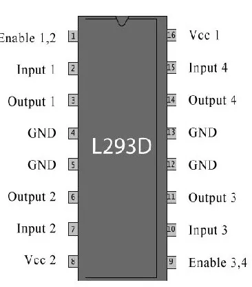
A motor driver IC is an integrated circuit chip which is usually used to control motors in autonomous
robots. Motor driver ICs act as an interface between microprocessors in robots and the motors in the robot. The most commonly used motor driver IC‟s are from the L293 series such as L293D, L293NE, etc. These ICs are designed to control 2 DC motors simultaneously. L293D consist of two bridge. H-bridge is the simplest circuit for controlling a low current rated motor. For this tutorial we will be referring the motor driver IC as L293D only. L293D has 16 pins,
The basic diagram of H-bridge is given below : In the given diagram, the arrow on the left points to the higher potential side of the input voltage of the circuit. Now if the switches S1 & S4 are kept in a closed position while the switches S2 & S3 are kept in a open position meaning that the circuit gets shorted across the switches S1 & S4. This creates a path for the current to flow, starting from the V input to switch S1 to the motor, then to switch S4 and then the exiting from the circuit. This flow of the current would make the motor turn in one direction. The direction of motion of the motor can be clockwise or anti-clockwise, this is because the rotation of the
motor depends
For simplicity, lets assume that in this condition the motor rotates in a clockwise direction. Now, when S3 and S2 are closed then and S1 and S4 are kept open then the current flows from the other direction and the motor will now definitely rotates in counter-clockwise direction
When S1 and S3 are closed
and S2 and S4 are open then the „STALL‟ condition will occur.
IV. PROJECT DESCRIPTION
In this project MEMS sensor is used as the input to the microcontroller in order to control the walking device. MEMS sensors are used in order to indicate to the microcontroller the direction of movement of two wheels of the walking device. The output of the MEMS sensor is given to the microcontroller
4.1. BLOCK DIAGRAM:
Fig 6.1 block diagram
4.2. SOFTWARE REQUIREMENTS:
Keil uVision4 IDE
Flash Magic
Embedded c language
Proteus for Hardware Stimulation
4.3. HARDWARE REQUIREMENTS:
1. Regulated Power Supply. 2. Microcontroller.
3. MEMS sensors. 4. DC motors. 5. Motor supply.
4.4. WORKING:
The device itself is built as a stable chassis with four caster wheels, equipped with battery power supply, electronics and two additional electrically driven wheels that enable it to move as a two-wheel robot (two of the caster wheels are lifted once driving wheels are attached). The interface between the devicechassis and the vertical support frame is made of a ball joint, equipped with adjustable coaxial springs that have limitedrange of motion in terms of off-vertical deflection angles.
The interface enables the user a certain degree of freedom in motion, but it also limits the user‟s motion if needed in order to prevent injuries in cases of tripping, stumbling or falling. The idea behind the Hoist project was to augment the manual control mode of the existing walking assist system by observing the patient and adapting the control strategy accordingly. For this purpose, user position determination and intention-based-control system was designed that allows the patient to control the motion of the device by perturbing its position in regards to the platform base.
This approach equates to a very intuitive way of controllingthe device, since the control system works towards maintaining the neutral position of the user in regards to the platform. The final result is a system that follows the motion User‟s position in regards to the platform is determined by observing the angles between the left/right (vertical) struts andthe base frame . For this purpose, strutsand frame are equipped with bespoke tilt sensors, allowing the relative angles between the frame and struts to be determined. The x-axis of the platform frame coordinate system is oriented towards the front of the device and the z-axis is oriented vertically in the up direction, while the y-axis is oriented towards the left side of the frame, creating a right handed Cartesian coordinate system.
angular velocities of the struts are relatively low due to the long length of the struts. By using the small angle approximation of the trigonometric functions, rotation transformations between the platform frame coordinate system to tilt sensor coordinate system can be handled individually for the rotations around the x and y axes. Let _ denote the angle of rotation around the sensor‟s y axis that rotates the platform frame coordinate system to a tilt sensor coordinate system and _ denote the angle of rotation around the sensor‟s x axis that rotates the platform frame coordinate system to a tilt sensor coordinate system. where d is the vertical distance between the elastic joints and horizontal user support strut, ds is the length of that strut (i.e. horizontal distance between the two vertical struts), while angles for the left and right strut, respectively. Since the deflection angle of the struts is limited, the above equations can be simplified by replacing the tan functions with the linear small-angle approximation, which results in _x _ d(_l+_r)2 , _y _ �d(_l+_r)2 and d(_r�_l)2ds. These perturbations are used for estimating the position of the user in regards to the platform, which directly indicates the intention of the user for motion. This is justified by the following assumptions: When the user intends to move in the forward direction, the user will initiate a move in that direction, causing its relative position in regards to the platform to move forward.
When the user intends to speed up or slow down, user‟s speed will increase or decrease, respectively. This directly results in relative position of the user in regards to the platform to change to more forward (user is accelerating) or more backwards (user is slowing down) position.When the user intends to change the direction of motion,the user will rotate his/her pelvis in that direction.
Based on these assumptions, the values of _x and _ Y can be used directly as an estimation of user intent for acceleration and turning, while the side motion _y can be used as a measurement of the user‟s walking (gait) quality. The control system must be robust enough to ignore normal oscillations in the signals that result from walking dynamics, however special care must be taken for allowing the userto execute controlled rapid stopping manoeuvres. Thus, the controller combines a regular P-controller and a filtered Pcontroller (PfP controller), a combination that allows the user to have the feeling of an immediate control (regular P part) and smooth changes in the average speed of the platform (filtered P part, that simulates the effect of an integrator. Such controller has a continuous transfer function of H(s) = KP +KP;f (_s+1)�1: Input dead-band with variable width was added to the controller to tackle the
problem of measurement (input) noise in vicinity of the user‟s neutral position and allow the user to keep the platform stationary when needed. Motion direction reversal situation is also handled separately, improving the deceleration during braking action.
CONCLUSION
The prototype of walk rehabilitation system with the implementation of the presented control system has been proven in experimental study for being very intuitive and easy to adopt by the users. Most indicative are the experimental runs executed in External control mode (remote control by the operator), which produced data, that clearly show a positive correlation between the user‟s intention (pelvic rotation) and the rotational velocity along the prescribed reference trajectory. The subjects were only instructed to follow the motion of the platform along the trajectory and since the pelvic rotation clearly exceeded the platform‟s orientation changes along the path, we assume that the presented approach to the prediction of the user‟s intention is valid and allows natural (intuitive) motion control of the platform. Precision of the reference trajectory shape execution improved by a large margin when the control was handed over to the subjects themselves, indicating their ability of precise control over the motion of the system. Interestingly, although leg injury simulation was used in run 6, results generally improved over those from run 3.
This can be explained by additional experience gained during runs 4 and 5 and system‟s ability to cope with stray input signals, originating from the injury-induced changes in their
walking patterns. Based on the encouraging experimental test results on healthy subjects, the proposed control system will be evaluated on subjects with reduced motor and/or cognitive abilities, where similar results are expected. This will enable us to further check the validity of the above claims and adequacy of the default control system parameters.
REFERENCES
[1] M. G. Bowden, A. E. Embry, L. A. Perry, and P. W. Duncan, “Rehabilitation of walking after stroke,” Current Treatment Options in Neurology, vol. 14, no. 6, pp. 521–530, 2012.
[2] A. Olenšek, J. Oblak, I. Cikajlo, P. Novak, K. Jere, and Z. Matjaˇci´c, “Adaptive dynamic balance training during overground walking with assistive device,” Proceedings of the IEEE RAS and EMBS International Conference on Biomedical Robotics and Biomechatronics, pp. 1066–1070, 2012.
lower limb rehabilitation robot,” in 2010 IEEE International Conference on Robotics and Biomimetics, ROBIO 2010, 2010, pp. 1233–1237. [4] J. F. Veneman, R. Kruidhof, E. E. G. Hekman, R. Ekkelenkamp, E. H. F. Van Asseldonk, and H. Van Der Kooij, “Design and evaluation of the LOPES exoskeleton robot for interactive gait rehabilitation,” IEEE Transactions on Neural Systems and Rehabilitation Engineering, vol. 15,
no. 1, pp. 379–386, 2007.
[5] A. J. Rentschler, R. Simpson, R. A. Cooper, and M. L. Boninger, “Clinical evaluation of Guido robotic walker.” Journal of rehabilitation research and development, vol. 45, no. 9, pp. 1281–1293, 2008.
[6] D. Chugo, T. Asawa, T. Kitamura, J. Songmin, and K. Takase, “A motion control of a robotic walker for continuous assistance during standing, walking and seating operation,” 2009 IEEE/RSJ International Conference on Intelligent Robots and Systems, IROS 2009, pp. 4487– 4492, 2009.
[7] B. Graf, M. Hans, and R. D. Schraft, “Care-O-bot II - Development of a Next Generation Robotic Home Assistant,” Autonomous Robots, vol. 16, no. 2, pp. 193–205, 2004.
[8] B. T. Tyson, M. T. Pham, N. T. Brown, and T. R. Mayer, “Patient Safety Considerations in the Rehabilitation of the Individual with Cognitive Impairment,” Physical Medicine and Rehabilitation Clinics of North America, vol. 23, no. 2, pp. 315– 334, may 2012. [Online]. Available: http://linkinghub.elsevier.com/retrieve/pii/S10479651 12000150
[9] {m}edica, “THERA-Trainer e-go (http://www.theratrainer.
e/english/professional/gait/thera-trainer-e-go/index.html),”2015. [Online]. Available: http://www.thera-trainer.de/english/