Distributed Energy Resources (DER or De) To
Regulate Voltages In Future Distribution
Systems with a High De Penetration
V Karthik
1, Errum Ali
2, Syed Mohd Saif Mirza
3, Syed Ehtesham Uddin
4,
Mohd Saber Hussain
51
Assistant Professor, Dept of EEE, Lords Institute of Engg.& Tech.,JNTUH,
Hyderabad,Telangana, India
2
Student, Dept of EEE, Lords Institute of Engg.& Tech., JNTUH, Hyderabad, Telangana, India
3Student, Dept of EEE, Lords Institute of Engg.& Tech., JNTUH,
Hyderabad, Telangana, India
4Student, Dept of EEE, Lords Institute of Engg.& Tech., JNTUH,
Hyderabad, Telangana, India
5Student, Dept of EEE, Lords Institute of Engg.& Tech.,
JNTUH,
Hyderabad, Telangana, India
ABSTRACT: - This project proposes a plug-and-play control method to coordinate multiple distributed energy resources (DER or DE) to regulate voltages in future distribution systems with a high DE penetration. Theoretical analysis shows that there exists a corresponding formulation of the dynamic control parameters with multiple DEs to give the desired responses. Therefore, the proposed control method has a solid theoretical basis. The method is based on dynamically and adaptively adjusting DE control parameters to ensure that actual voltage responses follow the desired outputs. Also, it is based on local and the other DEs’ voltages without the need of the full system data and extensive studies to tune the control parameters. Hence, the method is autonomous and adaptive for variable operational situations, and has the plug-and-play feature with a high tolerance to unavailable or inaccurate system data. Thus, it is suitable for broad utility application. Simulation results from various conditions, such as asynchronous start of multiple DEs, disappearance of the original disturbance in the middle of the control process, and operation in looped distribution systems, confirm the performance, validity, and flexibility of the proposed control method. The possible impact of communication latency on the performance of the proposed method is also discussed. The index terms in this project Adaptive control, ancillary services, communication latency, distributed energy resources, distributed generation, inverter control, micro grid, PI control, reactive power, smart grid, voltage control.
I.
INTRODUCTION
Distributed energy resources (DER or DE) or distributed generators (DG) to supply dynamic voltage regulation at the load demand side of power systems has received significant with the fast growth of PV systems and the fact that some utilities are experiencing high PV system penetration levels on distribution circuits, guidelines for voltage and reactive power (volt/var) regulation from DE are underway by the. Benefits of providing volt/var control from DE with power electronics (PE) interface, more specifically, an inverter, have been discussed in the literature. A noteworthy, but many times underestimated, benefit is that the DE inverter can provide significant var support by utilizing the remaining DE inverter capacity or via a slight increase
as minimizing line losses by using an optimal power flow (OPF) method. A method using local data history to dynamically set optimal voltage references for the DG to minimize system losses as well as maintaining an acceptable voltage profile. In addition to the research work from a steady-state viewpoint, some of the work focuses on dynamic study. Illustrate that grid-connected DE using a PE interface is capable of supplying voltage regulation service dynamically, in particular with the application of proportionalintegral-
differential (PID) controllers. However these papers focused on the control method PI controller parameters greatly affect the DE dynamic response for voltage regulation. However, when multiple DEs with voltage regulating capability are deployed in the system, their control could possibly chase against each other in achieving their individual control goals. It is a challenging task to coordinate their voltage regulator.
I. ADAPTIVE VOLTAGE CONTROL METHOD
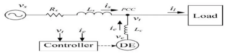
A simplified PE inverter interfaced with a DE connected in parallel with the distribution system through a coupling inductor.
Fig 1: Parallel Connection of A DE with PE Inverter to the Distribution System
The distribution system is simplified as an infinite voltage source (utility) with a system impedance of [rs+jwls].The voltage at the point of common coupling (PCC) is denoted as vt. By generating or consuming vars, the DE regulates vt. An adaptive voltage regulation method is developed based on the system configuration in Figure. 1 with a PI feedback controller. The PCC voltage (or terminal voltage),vt , is measured and its RMS value, , is calculated. The RMS value is then compared to a voltage reference vt*, (which could be a utility specified voltage schedule and possibly subject to adjustment based on load patterns like daily, seasonal, on-and-off peak, etc.). The error between the actual measurement and reference is fed back to adjust the reference DE output voltage, which is the reference for generating the pulse-widthmodulation (PWM) signals to drive the inverter. In this manner, the DE output voltage,vc , is controlled to regulate to match the PCC reference voltage,v* . The control scheme can be specifically expressed as
Fig. 2. Control Diagram For DE Voltage Regulation.
The control diagram is shown in Fig. 2. The PCC voltage (or terminal voltage), is measured and its RMS value, is calculated. The RMS value is then compared to a voltage reference, (which could be a utility specified voltage schedule and possibly subject to adjustment based on load patterns like daily, seasonal, on-and-off peak, etc.). The error between the actual measurement and reference is fed back to adjust the reference DE output voltage, which is the reference for generating the pulse-width modulation (PWM) signals to drive the inverter. In this manner, the DE output voltage, is controlled to regulate to match the PCC reference voltage, the control scheme can be specifically expressed as
2.1 Challenges of Multiple DEs for Voltage Regulation
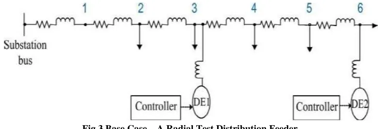
The impact of voltage regulation by multiple DEs on one of the DEs is tested in a distribution System modal analysis with two DEs connected to Bus 3 and Bus 6, respectively. Also, both DE controllers are set with fixed control gains. The paper refers to this as the Base Case.
Fig 3 Base Case—A Radial Test Distribution Feeder
Besides the impact on the response speed, multiple voltage regulating DEs complicate the var compensation direction. For instance, assume that initially, a DE’s local voltage is under its reference setting, which usually requires var injection. However, due to the simultaneous var injection from the other DEs, eventually this DE may be required to absorb vars to offset the local overvoltage. With the voltage profile along a feeder changed by the dispersed real power injections of DEs, this phenomenon would become common. Hence, it is important to draw the following conclusion with the case of multiple voltage-regulating DEs, the local voltage w.r.t. voltage reference may be a false indicator of absorption or injection of vars in regulating local voltage.
2.2 Analytical Formulation of Adaptive Method
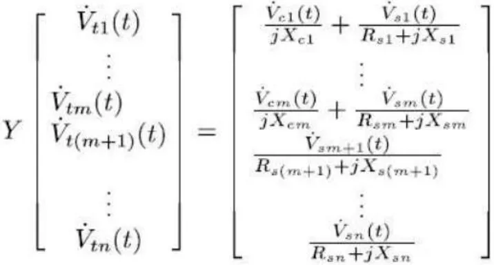
Fig 4 Schematic Diagram of a Network and With Multiple DE Sources
I.
IMPLEMENTATION OF ADAPTIVE METHOD FOR DE CONTROLLER
The dynamic control parameters Kp and KI can be theoretically calculated with the availability of the feeder data, including accurate load consumption and feeder line parameters. However the required information is usually difficult to obtain or inaccurate if indeed available. The implementation method proposed in this section does not require these parameters and it is able to plug-and-play by utilizing real time voltages information to automatically adjust the controller parameters. The proposed method assumes the availability of communications between the voltage-regulating DEs or with a control center to provide the real time information of DE operational conditions, including the terminal or PCC voltage at the other DE buses and the output voltage of every DE. However, the proposed method only requires limited communication at the beginning of the regulation and does not impose a large burden in terms of bandwidth on the communication systems.II.
IMPLEMENTATION FOR THE BASE CASE
A step-by-step example on two voltage-regulating DEs is shown in the following to illustrate the implementation procedures. The Base Case in Fig 5.1 is used for illustration.
Fig 5 Base Case—A Radial Test Distribution Feeder
The line-to-line voltage at the consumer side of the infinite bus is assumed to be 480 V (RMS). The total load of the system is 70.18kVA (59 kW, 38kVar). The active power injection of DE1 and DE2 is 10 kW and 20 kW, respectively, and they remain constant. The voltage references for Bus 3 and Bus 6 are 275.80 V and 275.60 V. Assume after a load increase, the voltages at Bus 3 and Bus 6 drop to 271.66 V and 271.76 V, respectively. The adjusting frequency is 60 Hz, aligned with the system frequency.
III.
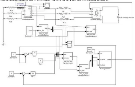
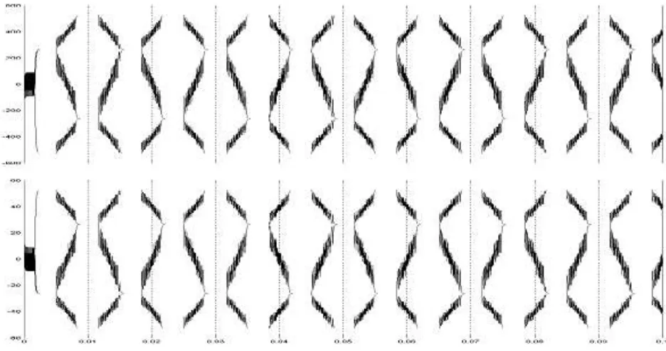
SIMULATION AND RESULT ANALYSIS
Fig 7: Simulation Result
IV.
CONCLUSION
The analysis and design of a high performance SPWM controller for three-phase UPS systems powering highly nonlinear loads. Although the classical SPWM method is very successful in controlling the RMS magnitude of the UPS output voltages, it cannot effectively compensate for the harmonics and the distortion caused by the nonlinear currents drawn by the rectifier loads. Therefore, this Thesis proposes a new strategy with a new design that overcomes the limitations of the classical RMS control. It adds inner loops to the closed loop control system effectively that enables successful reduction of harmonics and compensation of distortion at the voltages. The controller performance is evaluated experimentally using a three-phase 10 kVA transformer isolated UPS. A THD equal to 3.8% at the output voltage is achieved even under the worst nonlinear load. The load consists of three single-phase rectifiers connected between each line and the neutral and absorbing power equal to the rated power of the UPS with a crest factor up to 3. In conclusion, the experimental results demonstrate that the proposed controller successfully achieves the steady-state RMS voltage regulation specification as well as the THD and the dynamic response requirements of major UPS standards.
REFERENCES
[1] T. Kawabata, T. Miyashita, and Y. Yamamoto, ―Dead beat control of three phase PWM inverter,‖ IEEE Trans. Power Electron., vol. 5, no. 1, pp. 21– 28, Jan. 1990.
[2] N. M. Abdel-Rahim and J. E. Quaicoe, ―Analysis and design of a multiple feedback loop control strategy for single-phase voltage-source UPS inverters,‖ IEEE Trans. Power Electron., vol. 11, no. 4, pp. 532–541, Jul. 1996.
[3] M. J. Ryan, W. E. Brumsickle, and R. D. Lorenz, ―Control topology options for single-phase UPS inverters,‖ IEEE Trans. Ind. Appl., vol. 33, no. 2, pp. 493–501, Mar./Apr. 1997.
[5] Uninterruptible power systems (UPS)—Part 3: Method of specifying the performance and test requirements, First Edition 1999-03.
[6] U. Borup, P. N. Enjeti, and F. Blaabjerg, ―A new space-vector-based control method for UPS systems powering nonlinear and unbalanced loads,‖ IEEE Trans. Industry Appl., vol. 37, no. 6, pp. 1864–1870, Nov./Dec.2001.
[7] P.Mattavelli, ―Synchronous-frame harmonic control for high-performance AC power supplies,‖ IEEE Trans. Ind. Appl., vol. 37, no. 3, pp. 864–872, May/Jun. 2001.
[8] F. Botter´on, H. Pinheiro, H. A. Grundling, and J. R. P. H. L. Hey, ―Digital voltage and current controllers for three-phase PWM inverter for UPS applications,‖ in Proc. 36th Annu. Meeting IEEE Ind. Appl., Chicago, IL, Sep./Oct. 2001
[9] S. Buso, S. Fasolo, and P. Mattavelli, ―Uninterruptible power supply multiloop employing digital predictive voltage and current regulators,‖ IEEE Trans. Ind. Appl., vol. 37, no. 6, pp. 1846– 1854, Nov./Dec. 2001.
[10] C. Rech, H. Pinheiro, H. A. Grundling, H. L. Hey, and J. R. Pinheiro, ―Analysis and design of a repetitive predictive-PID controller for PWM inverters,‖ in Proc. IEEE 32nd Power Electron. Spec. Conf., Vancouver, BC, Canada, 2001.
[11] P. C. Loh, M. J. Newman, D. N. Zmood, and D. G. Holmes, ―A comparative analysis of multiloop voltage regulation strategies for single and three-phase UPS systems,‖ IEEE Trans. Power Electron., vol. 18, no. 5, pp. 1176–1185, Sep. 2003.
[12] K. Zhang, Y. Kang, J. Xiong, and J. Chen, ―Direct repetitive control of SPWM inverter for UPS purpose,‖ IEEE Trans. Power Electron., vol. 18, no. 3, pp. 784–792, May 2003.
[13] Y. Ye, K. Zhou, B. Zhang, D. Wang, and J. Wang, ―High-performance repetitive control of PWM DC-AC converters with real-time phase-lead FIR filter,‖ IEEE Trans. Circuits Syst. II, Exp. Briefs, vol. 53, no. 8, pp. 768–772, Aug. 2006.
[14] F. Botter´on and H. Pinheiro, ―A three-phase UPS that complies with the standard IEC 62040-3,‖ IEEE Trans. Ind. Electron., vol. 54, no. 4,pp. 2120– 2136, Aug. 2007.
[15] S. Yang, B. Cui, F. Zhang, and Z. Qian, ―A robust repetitive control strategy for CVCF inverters with very low harmonic distortion,‖ in Proc. IEEE Appl. Power Electron. Conf., 2007.
[16] G. Escobar, A. A. Valdez, J. Leyva-Ramos, and P.Mattavelli, ―Repetitivebased controller for a UPS inverter to compensate unbalance and harmonic distortion,‖ IEEE Trans. Ind. Electron., vol. 54, no. 1, pp. 504–510, Feb. 2007.
[17] H. Deng, R. Oruganti, and D. Srinivasan, ―Analysis and design of iterative learning control strategies for UPS inverters,‖ IEEE Trans. Ind. Electron., vol. 54, no. 3, pp. 1739–1751, Jun. 2007.
[18] E. Kim, J. Kwon, J. Park, and B. Kwon, ―Practical control implementation of a three-to single-phase online UPS,‖ IEEE Trans. Ind. Electron., vol. 55, no. 8, pp. 2933–2942, Aug. 2008.
[19] P. Cort´es, G. Ortiz, J. I. Yuz, J. Rodr´ıguez, S. Vazquez, and L. G. Franquelo, ―Model predictive control of an inverter with output LC filter for ups applications,‖ IEEE Trans. Ind. Electron., vol. 56, no. 6, pp.1875–1883, Jun. 2009.
[20] Q.-C. Zhong, F. Blaabjerg, J. Guerrero, and T. Hornik, ―Reduction of voltage harmonics for paralleloperated inverters equipped with a robust droop controller,‖ in Proc. IEEE Energy Convers. Congr. Expo., Phoenix, AZ, 2011.
BIBILOGRAPHY:
V Karthik, is Graduated from LIET, Himayatsagar, Hyderabad, Telangana in the year 2010,
Errum Ali is a final year student of Dept of Electrical and Electronics Engineering, Lords Inst of Engg. & Tech., Himayat sagar, Hyderabad, Telangana, India. She is pursuing her project study in the area of power systems and controller
Syed Mohd Saif Mirza is final year student of Dept of Electrical and Electronics Engineering,
Lords Inst of Engg. & Tech., Himayatsagar, Hyderabad, Telangana, India. He is pursuing his project study in the area of power systems and controller
Syed Ehtesham Uddin, is a final year student of Dept of Electrical and Electronics
Engineering, Lords Inst of Engg. & Tech. Himayatsagar, Hyderabad, Telangana, India. He is pursuing his project study in the area of power systems and controller
Mohd Saber Hussain, is a final year student of Dept of Electrical and Electronics